

Page 1
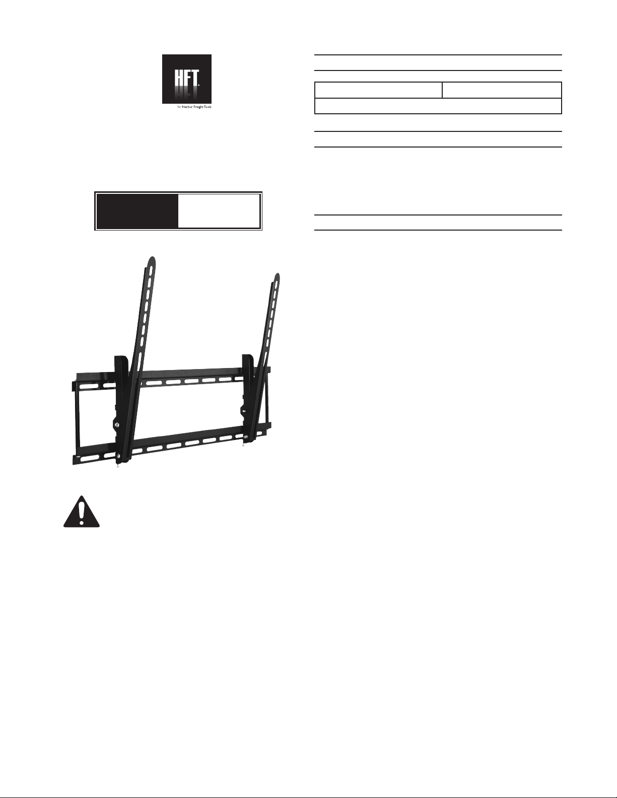
SPECIFICATIONS
Weight Capacity 150 lb.
For LED / LCD / Plasma TVs 37” to 61” wide
FLAT PANEL TV
WALL MOUNT
Model
INSTRUCTIONS AND PRECAUTIONS
Visit our website at: http://www.harborfreight.com
SAVE THESE
INSTRUCTIONS.
READ ALL
PRECAUTIONS AND
INSTRUCTIONS.
Copyright© 2010 by Harbor Freight Tools®. All rights
reserved. No portion of this document or any artwork
contained herein may be reproduced in any shape or form
without the express written consent of Harbor Freight
Tools. Diagrams within this document may not be drawn
proportionally. Due to continuing improvements, actual
product may differ slightly from the product described herein.
Tools required for assembly and service may not be included.
For technical questions or replacement parts,
please call 1-800-444-3353.
67781
UNPACKING
When unpacking, make sure that the item is
intact and undamaged. If any parts are missing or
broken, please call Harbor Freight Tools at
1-800-444-3353 as soon as possible.
IMPORTANT SAFETY INFORMATION
Do not exceed 150 lb. max. weight capacity of 1.
TV Bracket. Sudden load movement may briey
create excess load causing product failure.
Do not mount TV Bracket to hollow wall, gypsum 2.
board, or similar material that will not support the
weight of the TV. Mount only to 2” x 4” wood stud
or concrete/brick walls that can safely support
combined weight of Bracket, TV and all attached
hardware and components.
If you are unsure wall is strong enough to 3.
support weight of TV and TV Bracket, contact a
professional installer to reinforce wall.
Do not mount overhead.4.
Assemble and install only according to these 5.
instructions. Improper assembly and installation
can create hazards and lead to personal injury
and property damage.
Verify that mounting surface has no hidden utility 6.
lines before drilling or driving screws.
Wear ANSI-approved safety goggles and heavy-7.
duty work gloves during installation.
Inspect before installing; do not mount to wall if 8.
parts are missing, loose or damaged.
Use as intended only. Do not use TV Bracket for 9.
any purpose for which it was not designed.
Keep installation area clean and well lit.10.
Do not assemble or install when tired or when 11.
under the inuence of drugs or medication.
This product is not a toy. Do not allow children to 12.
play with or near this item.
Maintain product labels and nameplates. These 13.
carry important safety information. If unreadable
or missing, contact Harbor Freight Tools for a
replacement.
Page 2
ASSEMBLY AND MOUNTING
Read the ENTIRE IMPORTANT SAFETY
INFORMATION section at the beginning
of this document including all text under
subheadings therein before set up or use
of this product.
NOTE: The following tools (none supplied)
are required for mounting and installation:
Stud Finder, 11/16” socket, ratchet handle,
#2 Phillips screwdriver, 1/4” drill bit (for
drilling into wood stud), 1/2” masonry drill bit
(for drilling into brick or concrete wall), and
minimum 6” level, 5mm hex wrench, and
10mm combination wrench.
Before Installing
Use the 5mm hex wrench to double-check that 1.
all four socket screws of the Wall Bracket (1) are
tight. Tighten any connection, if needed.
Set Wall Bracket against the wall at the desired 2.
height. Place a level over the upper or lower
cross bar and adjust Bracket until level. Use a
marker to indicate locations of mounting holes.
Attaching to Wood Studs
First, verify woods studs are at least 16” apart. 1.
Use a Stud Finder (not included) to nd two
adjacent studs 16” apart. Use a marker to
indicate locations of the studs.
Drill four 1/4” holes at least 3-1/2” deep into the 2.
studs at the marked spots.
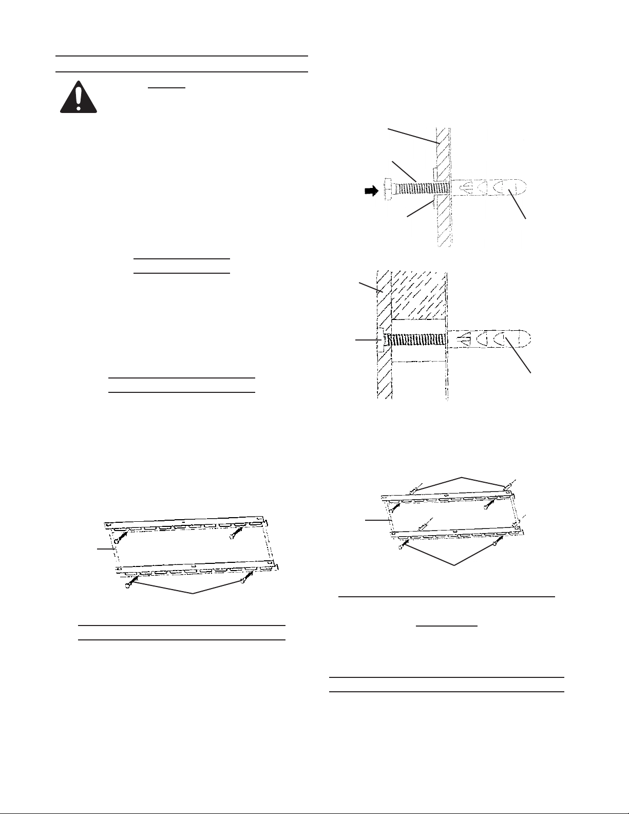
Use Lag Bolts (10) and Washers (9) to mount 3.
Wall Bracket to wall. See Figure 1, below.
Wall
Bracket
(1)
Attaching to Brick or Concrete Wall
NOTE: 1. Verify at least 6” of space are between
any two holes. Use 1/2” carbide tip masonry drill
bit and drill four 3-3/8” deep holes.
Insert the Wall Anchors (11) into the holes, 2.
making sure they are ush with the wall surface.
WARNING! 3. Wall Anchors must be set rmly
against concrete or masonry. If mounting to
Lag Bolt (10) and Washer (9)
Figure 1
a masonry wall covered with drywall/plaster,
counter bore a hole through drywall/plaster
around mounting holes’ locations. This will allow
Wall Anchors to be set directly against concrete
or masonry. See Figures 2a and 2b, below.
Wall Bracket (1)
Bolt (10)
Lag
Concrete
Washer
(9)
Wall
Anchor (11)
Wall
Bracket
(1)
Figure 2a
Concrete
Lag
Bolt
(10)
Plaster/
Drywall
Wall
Anchor (11)
Figure 2b
Once Wall Anchors are securely set into 4.
concrete, use Lag Bolts and Washers to install
Wall Bracket to wall. See Figure 3, below.
Wall Anchor (12)
Wall
Bracket
(1)
Lag Bolt (11) and Washer (10)
Figure 3
Attaching to Metal Studs or Concrete
Block Wall
NOTE: 1. If mounting to steel stud wall or cinder
block wall, alternative mounting hardware is
required.
Installing Support Arms to Flat Panel TV
WARNING! 1. Verify TV is unplugged before
threading any Screw into the TV’s back panel.
Page 2For technical questions, please call 1-800-444-3353.SKU 67781
Page 3

WARNING!2. Do no lay at panel TV face down;
cover its surface with a towel or other soft
material and tilt it against the wall or another solid
surface.
WARNING!3. Some Flat Panel TVs are heavy; two
people may be needed to lift and support the TV
while it is being attached to the TV Bracket.
Locate the mounting holes on back of TV and 4.
select mounting Screws (3-6) that t properly.
NOTE: If you do not nd the appropriate-sized
Screws, refer to TV owners manual or contact TV
manufacturer. Thread the Screws (3, 4, 5 or 6)
through the Square Pads (8), the Support Arms
(2), Spacers (7) and into the mounting holes in
the back of TV panel. See Figure 4, below.
Screws (3-6)
Square Pad (8)
Spacer (7)
Support
Arms (2)
Figure 4
TV Panel
NOTE: 5. The wide part of the Spacers rest against
the Support Arms.
Carry TV to mounted Bracket and lower onto 6.
Cross Bars, making sure the four tabs of the
mounts are hooked onto the top of Cross Bars
and that TV is centered. See Figure 5.
Cross Bars
Figure 5
Tighten the two clamping screws leaving about 7.
an eight of an inch space. See Figure 6.
Clamping
Screw
Figure 6
To adjust the TV angle, back off the two nuts at 8.
the Support Arm hinges by one turn. Back off
the two angle-adjusting screws located at the
sides of the Support Arms until end of the screw
threads are almost ush with the other side of the
Support Arms. See Figure 7.
Angle Adjusting
Screw
Angle Adjusting
Screw
Figure 7
CAUTION: 9. Make sure that the end of the screws
does not come out of the Support Arms.
Tilt the TV to the desired angle (four approximate 10.
adjustment positions = 0°, 3°, 7° and 12°).
Tighten the Angle-adjusting screws all the way to
lock the angle position.
Page 3For technical questions, please call 1-800-444-3353.SKU 67781
Page 4

PARTS LIST & ASSEMBLY DIAGRAM
Part Description Qty.
1 Wall Bracket 1
2 Support Arm 2
3 Screw (M4 x .7 x 35mm) 4
4 Screw (M5 x .8 x 35mm) 4
5 Screw (M6 x 1.0 x 35mm) 4
6 Screw (M6 x 1.25 x 35mm) 4
7 Spacer 4
8 Square Pad 4
9 Washer 4
10 Lag Bolt 4
11 Wall Anchor 4
2
1
3
7
8
4
9
5
10
6
11
Record Serial Number Here:
Note: If product has no serial number, record month and year of purchase instead.
Note: Some parts are listed and shown for illustration purposes only, and are not available individually as
replacement parts.
PLEASE READ THE FOLLOWING CAREFULLY
THE MANUFACTURER AND/OR DISTRIBUTOR HAS PROVIDED THE PARTS LIST AND ASSEMBLY DIAGRAM IN THIS DOCUMENT AS
A REFERENCE TOOL ONLY. NEITHER THE MANUFACTURER OR DISTRIBUTOR MAKES ANY REPRESENTATION OR WARRANTY
OF ANY KIND TO THE BUYER THAT HE OR SHE IS QUALIFIED TO MAKE ANY REPAIRS TO THE PRODUCT, OR THAT HE OR SHE
IS QUALIFIED TO REPLACE ANY PARTS OF THE PRODUCT. IN FACT, THE MANUFACTURER AND/OR DISTRIBUTOR EXPRESSLY
STATES THAT ALL REPAIRS AND PARTS REPLACEMENTS SHOULD BE UNDERTAKEN BY CERTIFIED AND LICENSED TECHNICIANS,
AND NOT BY THE BUYER. THE BUYER ASSUMES ALL RISK AND LIABILITY ARISING OUT OF HIS OR HER REPAIRS TO THE
ORIGINAL PRODUCT OR REPLACEMENT PARTS THERETO, OR ARISING OUT OF HIS OR HER INSTALLATION OF REPLACEMENT
PARTS THERETO.
Page 4For technical questions, please call 1-800-444-3353.SKU 67781
 Loading...