

Page 1
Weight Distribution hitch
Model
67649
set up anD operating instructions
Visit our website at: http://www.harborfreight.com
read this material before using this product.
Failure to do so can result in serious injury.
saVe this Manual.
Copyright© 2010 by Harbor Freight Tools®. All rights reserved. No portion of this manual or any artwork
contained herein may be reproduced in any shape or form without the express written consent of
Harbor Freight Tools. Diagrams within this manual may not be drawn proportionally. Due to continuing
improvements, actual product may differ slightly from the product described herein. Tools required for
assembly and service may not be included.
For technical questions or replacement parts, please call 1-800-444-3353.
Page 2
saVe this Manual
Keep this manual for the safety warnings
and precautions, assembly, operating,
inspection, maintenance and cleaning
procedures. Write the product’s serial number
in the back of the manual near the assembly
diagram (or month and year of purchase if
product has no number). Keep this manual
and the receipt in a safe and dry place for
future reference.
iMportant saFetY
inForMation
in this manual, on the labeling, and
all other information provided with
this product:
this is the safety alert
symbol. it is used to alert
you to potential personal
injury hazards. obey all
safety messages that follow
this symbol to avoid possible
injury or death.
notice is used to
address practices not
related to personal injury.
caution, without the
safety alert symbol, is
used to address practices not
related to personal injury.
hitch safety Warnings
Warning! read all safety warnings
and instructions. Failure to follow the
warnings and instructions may result
in serious injury.
save all warnings and instructions
for future reference.
The warnings, precautions, and
instructions discussed in this
instruction manual cannot cover all
possible conditions and situations that
may occur. It must be understood
by the operator that common sense
and caution are factors which cannot
be built into this product, but must be
supplied by the operator.
Danger indicates a
hazardous situation
which, if not avoided, will result
in death or serious injury.
Warning indicates a
hazardous situation
which, if not avoided, could
result in death or serious injury.
caution, used with
the safety alert
symbol, indicates a hazardous
situation which, if not avoided,
could result in minor or moderate
injury.
Page 2 For technical questions, please call 1-800-444-3353. SKU 67649
Page 3

installation/attachment safety
operation safety
Assemble only according to these 1.
instructions. Improper assembly can
create hazards. carefully measure
and follow all steps and adjustment
instructions.
Raise the front of the trailer 2. WHeNeveR
tension will be applied or released from
the Connection Brackets (3).
Adjust both chains to equal length.3.
When applying or releasing tension 4.
from the Brackets, use the Handle (5)
supplied and handle carefully.
the spring bars (4) Must be removed 5.
if the trailer is not attached.
Check local regulations to determine if
other components can be left in place or
must also be temporarily removed.
Wear ANSI-approved safety goggles and 6.
heavy-duty work gloves during assembly.
Secure the Spring Clips (18) and adjust 1.
according to this manual before use.
This product is not a toy. Do not allow 2.
children to play with or near this item.
Use as intended only.3.
Inspect before every use; do not use if 4.
parts are loose or damaged.
Do not exceed hitch’s rated capacities - 5.
see SpeciFicationS chart.
Maintain product labels and nameplates. 6.
These carry important safety information.
If unreadable or missing, contact Harbor
Freight Tools for a replacement.
Carefully load trailer according to trailer 7.
supplier’s instructions, whether a weight
distributing hitch is used or not.
Use according to DOT regulations.8.
Keep assembly area clean and well lit.7.
Keep bystanders out of the area during 8.
assembly.
Do not assemble when tired or when 9.
under the inuence of drugs or
medication.
Install according to DOT regulations.10.
service
Have your hitch serviced by a qualied 1.
repair person using only identical
replacement parts. This will ensure that
the safety of the hitch is maintained.
Do not use damaged equipment. If 2.
abnormal noise or vibration occurs, have
the problem corrected before further use.
saVe these
instructions.
Page 3For technical questions, please call 1-800-444-3353.SKU 67649
Page 4
speciFications
entire System
Capacity
Hitch Capacity
without Spring Bars
Shank Size 2” Square
1,000 lb. Tongue Weight
10,000 lb. Gross Trailer Weight
500 lb. Tongue Weight
5,000 lb. Gross Trailer Weight
Weight
Distribution
head (2)
spring
bar (4)
Class
III & Iv
note: For greater stability, a Sway Control
Kit (ITeM 96462, sold separately) can be
used along with this Hitch.
note: Limit capacities listed above by the
capacity of the towing vehicle and any
other attachment hardware used.
unpacking
When unpacking, make sure that all
parts listed on page 10 are included. If any
parts are missing or broken, please call
Harbor Freight Tools at 1-800-444-3353 as
soon as possible.
installation
read the entire iMportant
saFetY inForMation
section at the beginning of this
manual including all text under
subheadings therein before set up
or use of this product.
note: For additional information regarding the
parts listed in the following pages, refer
to the Assembly Diagram near the end of
this manual.
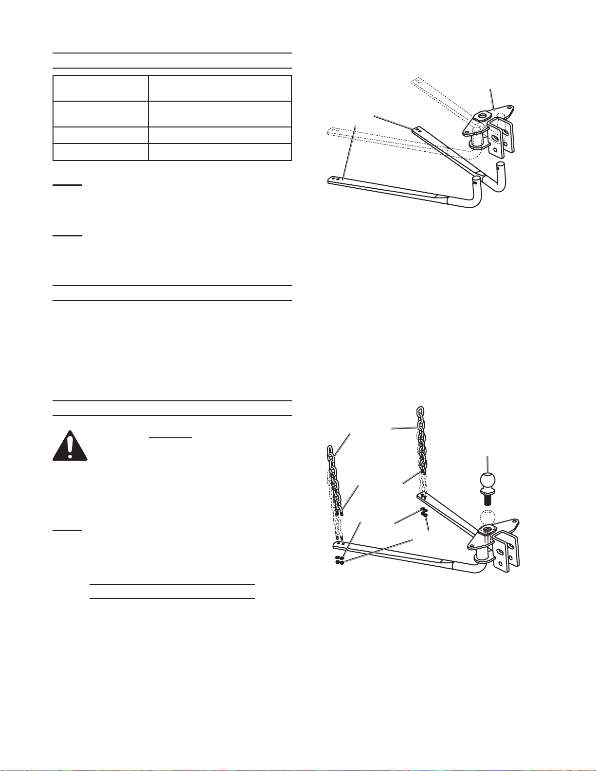
3. Hold the Spring back while installing the
Spring Bar into the socket on the Weight
Distribution Head (2).
4.
Release the Spring, and adjust the
Spring Bar until the spring snaps back
into place.
Pull on the Spring Bar to make sure 5.
it is properly attached to the Weight
Distribution Head.
6.
Repeat for the other Retaining Pin
Spring (2a) and the other Spring Bar (4).
chain (7)
u-bolt (8)
Washer
(9)
lock
nut (10)
hitch ball
(sold
separately)
spring bar (4) installation
7. Remove the Lock Nuts (10) and
Washers (9) from the U-bolts (8). Place
Apply some axle grease to the round end 1.
of one Spring Bar (4).
a U-bolt (8) around the bottom link of
each Chain (7). Insert the threaded ends
of each U-bolt into the holes at the end
Pry one of the Retaining Pin Springs (2a) 2.
back, pulling the Bar Retaining Pin (2b)
of each Spring Bar, as shown. Secure
with Washers (9) and Lock Nuts (10).
outwards .
Page 4 For technical questions, please call 1-800-444-3353. SKU 67649
Page 5

hitch ball installation
Install a properly sized and properly
rated hitch ball into the hole at the top of
the Weight Distribution Head (2).
Secure in place using the washer(s) and
nut(s) provided with the hitch ball.
Weight Distribution
head (2) installation
Determine the required ball height:1.
Divide tongue weight by 200 for tow a.
vehicles with overload springs, divide it
by 100 for vehicles without overload
springs and multiply the result to
calculate tow vehicle ‘squat’:
_______ lb. Tongue wt.
200 (if tow vehicle has overload springs)
or
–:
100
= _______
X 1/8”
= _______ ” tow vehicle ‘squat’
Position trailer parallel b.
to the ground on a
at, level surface and
measure the distance
from the ground to the
top of the ball cup
and write it here:
_________ ” coupler height
Add the distance found in step 1a to c.
the distance from step 1b to get the
required ball height:
______ ” tow vehicle ‘squat’ (step 1a)
+ ______ ” coupler height (step 1b)
= ______ ” required ball height
Insert Square Shank (1) into tow vehicle 2.
receiver. Secure it in place with the Lock
Pin (17) and the Spring Clip (18).
(if tow vehicle has no overload springs)
coupler
coupler
height
ground
highest
setting
Weight
Distribution
head (2)
loWest
setting
3. Determine the attachment point of the
Weight Distribution Head (2) to the
Square Shank (1) according to the
needed connection height calculated
in step 1c. The Square Shank can be
turned upside-down if needed.
each hole is 1-1/4” of adjustment.
Insert one of the 3/4” Bolts (16) through
the lower hole to hold the Weight
Distribution Head (2) in place for now.
Thread a 3/4” Nut (12) onto the Bolt, but
do not tighten it yet.
spacing
Washers
(13)
Weight
Distribution
head (2)
angle set
bolt (2c)
spacing
rivet (14)
toothed
Washer
(15)
square
shank
(1)
bolts (16)
4. Adjust the Spring Bars’ (4) angle using
the Spacing Rivet (14) and from 0 to 7
Spacing Washers (13) until the Spring
Bars tilt downward slightly (10-13°).
Loosen the Angle Set Bolt (2c) before
adding/removing Spacing Washers (13)
and tighten afterwards.
square
shank (1)
Page 5For technical questions, please call 1-800-444-3353.SKU 67649
Page 6

bolt (16)
toothed
Washer (15)
connection bracket installation
nut (12)
connection
bracket (3)
square
shank (1)
Weight Distribution
head (2)
5. After the angle is set properly, insert a
Bolt (16) through the upper hole in the
Weight Distribution Head (2), Toothed
Washers (15), and a Nut (12) as shown
above. Tighten securely.
Tighten both 3/4” Nuts (12) to 260 ft-lb 6.
of torque using a torque wrench (sold
separately).
1
/2” bolts (6)
trailer and hitch
(sold separately)
connection
bracket (3)
1. Thread a 1/2” Bolt (6) into each
Connection Bracket (3) a turn or two.
Place the Connection Brackets (3) on
top of the trailer tongue with the Bolts (6)
facing inwards as shown above.
Swing the Spring bars down under the
2.
brackets, and pull the Chains straight up
with no twist. Position each Connection
Bracket directly above its chain.
Tighten the 1/2” Bolts (6) until they 3.
contact the trailer and then 1/4 turn
more. Do not overtighten.
permanently installed
components are now in place:
Proceed to operation for nal setup and 1.
trailer attachment.
if trailer is not to be attached at this 2.
time, the spring bars (4) Must be
removed:
Hold onto the Spring Bar while prying the
Retaining Pin Spring (2a) back, pulling
the Bar Retaining Pin (2b) outwards.
The Spring Bar should drop out of the
Weight Distribution Head (2).
Check local regulations to determine if
other components can be left in place or
must also be temporarily removed.
Page 6 For technical questions, please call 1-800-444-3353. SKU 67649
Page 7

attachMent
read the entire iMportant
saFetY inForMation
section at the beginning of this
manual including all text under
subheadings therein before set up
or use of this product.
note: For additional information regarding the
parts listed in the following pages, refer
to the Assembly Diagram near the end of
this manual.
If Spring Bars (4) were removed, reinstall 1.
them following steps 1 through 6 on
page 4.
slide handle
b:
over pin on bracket and
rotate up to secure chain
a: connect
chain to
hook
chain (7)
handle (5)
connection
bracket (3)
c: insert
clip to lock
spring
clip (18)
While trailer is not connected, measure 2.
the distance from front and rear bumpers
of towing vehicle to ground.
Write here: _______ front to ground
_______ rear to ground
Lower trailer coupler onto hitch ball and 3.
secure the trailer’s ball coupler in place.
raise the front of trailer and back of 4.
the towing vehicle 3”.
this will make mounting easier and
safer.
Swing the hooks on the Connection 5.
Brackets (3) down.
6. Connect Chains:
Connect the Chains (7) to the hooks on a.
the Connection Brackets (3).
Slide Handle (5) over pin on Bracket b.
and rotate up completely to secure
Chain.
Insert Spring Clip through bracket as c.
shown to lock chain in place.
d.
Repeat for other bracket and chain.
both chains must be of equal length.
Lower the front of the trailer.7.
Re-measure height of front and back of 8.
towing vehicle. Both should be lower
than the amounts written in step 2 by an
equal distance or up to 1” lower in back.
The chain lengths need be adjusted (by
releasing the Brackets and adjusting
each chain one link at a time) until that
measurement is achieved. verify that
the chains are adjusted to same length.
note: the brackets will be under tension;
use the handle (5) supplied and
handle carefully to prevent injury.
raise the front of the trailer
WheneVer tension will be applied or
released from the brackets.
Page 7For technical questions, please call 1-800-444-3353.SKU 67649
Page 8

aFter use
Note the number of chain links used to 1.
make reconnection to the same trailer
and load easier.
raise the front of trailer and back of 2.
the towing vehicle 3”.
this will make disconnection easier
and safer.
note: the brackets will be under tension,
use the handle (5) supplied and
handle carefully to prevent injury.
Slide Handle (5) over pin on Bracket and 3.
careFullY rotate down completely to
release Chain. Repeat for other side.
Disconnect trailer from hitch ball.4.
the spring bars (4) Must be removed 5.
if the trailer is not attached:
Hold onto the Spring Bar while prying the
Retaining Pin Spring (2a) back, pulling
the Bar Retaining Pin (2b) outwards.
The Spring Bar should drop out of the
Weight Distribution Head (2).
Check local regulations to determine if
other components can be left in place or
must also be temporarily removed.
Page 8 For technical questions, please call 1-800-444-3353. SKU 67649
Page 9

Maintenance anD
serVicing
Proceduresnotspecically
explained in this manual must
beperformedonlybyaqualied
technician.
to preVent
serious injurY
FroM acciDental
operation:
Disconnect hitch as explained
under AFTER USE before
performing any inspection,
maintenance, or cleaning
procedures.
to preVent serious injurY
FroM hitch Failure:
Do not use damaged equipment.
if abnormal noise or vibration
occurs, have the problem
corrected before further use.
please reaD the FolloWing
careFullY
THe MANUFACTUReR AND/OR DISTRIBUTOR
HAS PROvIDeD THe PARTS LIST AND ASSeMBLy
DIAGRAM IN THIS MANUAL AS A ReFeReNCe
TOOL ONLy. NeITHeR THe MANUFACTUReR OR
DISTRIBUTOR MAKeS ANy RePReSeNTATION
OR WARRANTy OF ANy KIND TO THe BUyeR
THAT He OR SHe IS qUALIFIeD TO MAKe ANy
RePAIRS TO THe PRODUCT, OR THAT He OR SHe
IS qUALIFIeD TO RePLACe ANy PARTS OF THe
PRODUCT. IN FACT, THe MANUFACTUReR AND/
OR DISTRIBUTOR exPReSSLy STATeS THAT ALL
RePAIRS AND PARTS RePLACeMeNTS SHOULD
Be UNDeRTAKeN By CeRTIFIeD AND LICeNSeD
TeCHNICIANS, AND NOT By THe BUyeR. THe
BUyeR ASSUMeS ALL RISK AND LIABILITy ARISING
OUT OF HIS OR HeR RePAIRS TO THe ORIGINAL
PRODUCT OR RePLACeMeNT PARTS THeReTO,
OR ARISING OUT OF HIS OR HeR INSTALLATION
OF RePLACeMeNT PARTS THeReTO.
beFore each use,1. inspect the
general condition of the tool. Check for
loose hardware, misalignment or binding
of moving parts, cracked or broken parts,
damaged electrical wiring, and any
other condition that may affect its safe
operation.
aFter use,2. wipe external surfaces of
the tool with clean cloth.
Inject axle grease into the grease 3.
ttings on the Weight Distribution Head
(2) monthly if the Spring Bars are left
installed.
Before installing the Spring Bars (4), 4.
clean and apply axle grease to the
rounded end.
Page 9For technical questions, please call 1-800-444-3353.SKU 67649
Page 10

parts list
part Description Qty.
1 Square Shank 1
2 Weight Distribution Head 1
2a Retaining Pin Spring 2
2b Bar Retaining Pin 2
2c Angle Set Bolt 1
2d Grease Fitting 2
3 Connection Bracket 2
4 Spring Bar (1000 lb. rating) 2
5 Handle 1
6 1/2" x 3-3/4" Bolt 2
7 3/8" Chain (9 links) 2
8 3/8" U-bolt 2
9 3/8" Washer 4
10 3/8" Lock Nut 4
11 Bushing 1
12 3/4" Nut 2
13 1/2" Spacing Washer 7
14 1-1/2" x 1-1/4" Spacing Rivet 1
15 Toothed Washer 2
16 3/4" x 4 1/2" Bolt 2
17 5/8" Lock Pin 1
18 Spring Clip 3
record product’s serial number here:
note: If product has no serial number, record month and year of purchase instead.
note: Some parts are listed and shown for illustration purposes only, and are not available
individually as replacement parts.
Page 10 For technical questions, please call 1-800-444-3353. SKU 67649
Page 11

asseMblY DiagraM
2c
Washers (13)
hole for spacing
and spacing
rivet (14)
2b
2a
View from front of Weight Distribution head (2)
2b
Page 11For technical questions, please call 1-800-444-3353.SKU 67649
Page 12

liMiteD 90 DaY WarrantY
Harbor Freight Tools Co. makes every
effort to assure that its products meet
high quality and durability standards, and
warrants to the original purchaser that this
product is free from defects in materials and
workmanship for the period of 90 days from
the date of purchase. This warranty does not
apply to damage due directly or indirectly,
to misuse, abuse, negligence or accidents,
repairs or alterations outside our facilities,
criminal activity, improper installation, normal
wear and tear, or to lack of maintenance. We
shall in no event be liable for death, injuries
to persons or property, or for incidental,
contingent, special or consequential damages
arising from the use of our product. Some
states do not allow the exclusion or limitation
of incidental or consequential damages,
so the above limitation of exclusion may
not apply to you. THIS WARRANTy IS
exPReSSLy IN LIeU OF ALL OTHeR
WARRANTIeS, exPReSS OR IMPLIeD,
INCLUDING THe WARRANTIeS OF
MeRCHANTABILITy AND FITNeSS.
To take advantage of this warranty,
the product or part must be returned to us
with transportation charges prepaid. Proof
of purchase date and an explanation of the
complaint must accompany the merchandise.
If our inspection veries the defect, we
will either repair or replace the product at
our election or we may elect to refund the
purchase price if we cannot readily and
quickly provide you with a replacement. We
will return repaired products at our expense,
but if we determine there is no defect, or that
the defect resulted from causes not within the
scope of our warranty, then you must bear the
cost of returning the product.
This warranty gives you specic legal
rights and you may also have other rights
which vary from state to state.
3491 Mission Oaks Blvd. • PO Box 6009
Camarillo, CA 93011 • (800) 444-3353
Page 12 For technical questions, please call 1-800-444-3353. SKU 67649
 Loading...