

Page 1
Owner’s Manual & Safety Instructions
Save This Manual Keep this manual for the safety warnings and precautions, assembly, operating,
inspection, maintenance and cleaning procedures. Write the product’s serial number in the back of the manual
near the assembly diagram (or month and year of purchase if product has no number). Keep this manual and
the receipt in a safe and dry place for future reference.
VIBRATORY
TUMBLER
Visit our website at: http://www.harborfreight.com
Email our technical support at: tech@harborfreight.com
When unpacking, make sure that the product is intact
and undamaged. If any parts are missing or broken,
please call 1-800-444-3353 as soon as possible.
Copyright© 2012 by Harbor Freight Tools®. All rights reserved.
No portion of this manual or any artwork contained herein may be reproduced in
any shape or form without the express written consent of Harbor Freight Tools.
Diagrams within this manual may not be drawn proportionally. Due to continuing
improvements, actual product may differ slightly from the product described herein.
Tools required for assembly and service may not be included.
ITEM 67617
Read this material before using this product.
Failure to do so can result in serious injury.
SAVE THIS MANUAL.
Page 2

Table of Contents
Safety ......................................................... 2
Specifications ............................................. 6
Setup .......................................................... 6
SAFETY OPERATION MAINTENANCESETUP
Operation .................................................... 7
This is the safety alert symbol. It is used to alert you to potential personal injury hazards.
Maintenance ............................................... 9
Parts List and Diagram .............................. 10
Warranty .................................................... 12
WARNING SYMBOLS AND DEFINITIONS
Obey all safety messages that follow this symbol to avoid possible injury or death.
Indicates a hazardous situation which, if not avoided,
will result in death or serious injury.
Indicates a hazardous situation which, if not avoided,
could result in death or serious injury.
Indicates a hazardous situation which, if not avoided,
could result in minor or moderate injury.
Addresses practices not related to personal injury.
IMPORTANT SAFETY INFORMATION
General Tool Safety Warnings
Read all safety warnings and instructions.
Failure to follow the warnings and instructions may result in electric shock, fire and/or serious injury.
Save all warnings and instructions for future reference.
1. KEEP WORK AREA CLEAN.
Cluttered areas and benches invite accidents.
2. DON’T USE IN DANGEROUS ENVIRONMENT.
Don’t use power tools in damp or wet locations,
or expose them to rain. Keep work area well lighted.
3. KEEP CHILDREN AWAY. All visitors should
be kept safe distance from work area.
4. MAKE WORKSHOP KID PROOF with padlocks,
master switches, or by removing starter keys.
5. DON’T FORCE TOOL. It will do the job better
and safer at the rate for which it was designed.
6. USE RIGHT TOOL. Don’t force tool or attachment
to do a job for which it was not designed.
Page 2 For technical questions, please call 1-800-444-3353. Item 67617
Page 3

General Tool Safety Warnings (cont.)
Table A: RECOMMENDED MINIMUM WIRE GAUGE
FOR EXTENSION CORDS
(120 VOLT)
NAMEPLATE
AMPERES
(at full load)
0 – 6 18 16 16 14
6.1 – 10 18 16 14 12
10.1 – 12 16 16 14 12
12.1 – 16 14 12 Do not use.
7. USE PROPER EXTENSION CORD. Make sure your
extension cord is in good condition. When using
an extension cord, be sure to use one heavy
enough to carry the current your product will
draw. An undersized cord will cause a drop in line
voltage resulting in loss of power and overheating.
Table A shows the correct size to use depending
on cord length and nameplate ampere rating.
If in doubt, use the next heavier gauge.
The smaller the gauge number, the heavier the cord.
8. WEAR PROPER APPAREL. Do not wear
loose clothing, gloves, neckties, rings, bracelets,
or other jewelry which may get caught in moving
parts. Nonslip footwear is recommended.
Wear protective hair covering to contain long hair.
9. DON’T OVERREACH. Keep proper
footing and balance at all times.
EXTENSION CORD
LENGTH
25′ 50′ 100′ 150′
10. MAINTAIN TOOLS WITH CARE. Keep tools sharp
and clean for best and safest performance. Follow
instructions for lubricating and changing accessories.
11. DISCONNECT TOOLS before servicing;
when changing accessories, such as
blades, bits, cutters, and the like.
12. REDUCE THE RISK OF UNINTENTIONAL
STARTING. Make sure switch is in
off position before plugging in.
13. USE RECOMMENDED ACCESSORIES.
Consult the owner’s manual for recommended
accessories. The use of improper accessories
may cause risk of injury to persons.
14. NEVER STAND ON TOOL. Serious injury
could occur if the tool is tipped or if the
cutting tool is unintentionally contacted.
15. CHECK DAMAGED PARTS. Before further use
of the tool, a guard or other part that is damaged
should be carefully checked to determine that
it will operate properly and perform its intended
function – check for alignment of moving parts,
binding of moving parts, breakage of parts,
mounting, and any other conditions that may
affect its operation. A guard or other part that is
damaged should be properly repaired or replaced.
16. NEVER LEAVE TOOL RUNNING UNATTENDED.
TURN POWER OFF. Don’t leave tool
until it comes to a complete stop.
SAFETYOPERATIONMAINTENANCE SETUP
Page 3For technical questions, please call 1-800-444-3353.Item 67617
Page 4
Grounding Instructions
SAFETY OPERATION MAINTENANCESETUP
TO PREVENT ELECTRIC SHOCK AND DEATH FROM INCORRECT GROUNDING WIRE CONNECTION
READ AND FOLLOW THESE INSTRUCTIONS:
110-120 V~ Grounded Tools: Tools with Three Prong Plugs
1. In the event of a malfunction or breakdown,
grounding provides a path of least resistance for
electric current to reduce the risk of electric shock.
This tool is equipped with an electric cord having an
equipment-grounding conductor and a grounding
plug. The plug must be plugged into a matching
outlet that is properly installed and grounded in
accordance with all local codes and ordinances.
2. Do not modify the plug provided – if it will
not fit the outlet, have the proper outlet
installed by a qualified electrician.
3. Improper connection of the equipment-grounding
conductor can result in a risk of electric shock.
The conductor with insulation having an outer
surface that is green with or without yellow
stripes is the equipment-grounding conductor.
If repair or replacement of the electric cord or
plug is necessary, do not connect the equipmentgrounding conductor to a live terminal.
4. Check with a qualified electrician or service
personnel if the grounding instructions are
not completely understood, or if in doubt as
to whether the tool is properly grounded.
5. Use only 3-wire extension cords that
have 3-prong grounding plugs and 3-pole
receptacles that accept the tool’s plug.
6. Repair or replace damaged or worn cord immediately.
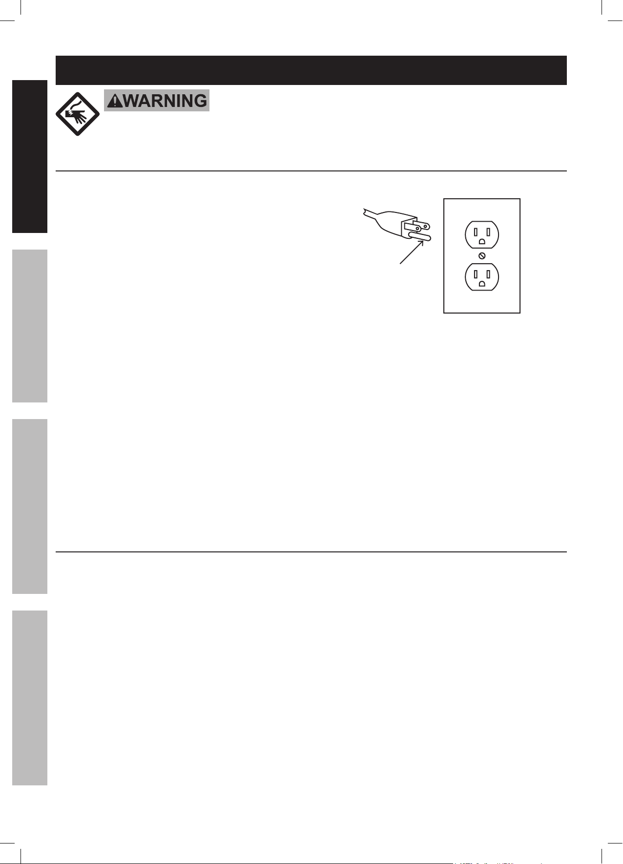
Grounding
Pin
125 V~ 3-Prong Plug and Outlet
(for up to 125 V~ and up to 15 A)
7. This tool is intended for use on a circuit that has
an outlet that looks like the one illustrated above in
125 V~ 3-Prong Plug and Outlet. The tool has a
grounding plug
that looks like the plug illustrated above
in 125 V~ 3-Prong Plug and Outlet.
8. The outlet must be properly installed and grounded
in accordance with all codes and ordinances.
9. Do not use an adapter to connect
this tool to a different outlet.
Tumbler Safety Warnings
1. Do not use ceramic, wet or water based
media in Tumbler. Use only plastic beads,
ground corn cobs, walnut shells, etc.
2. Do not use to polish stones. A rotary tumbler
(such as 65838 Rotary Rock Tumbler or 65840
Dual Drum Rotary Rock Tumbler) and watermixed media is required for polishing stones.
3. Do not exceed 5 lb. Tank capacity.
4. Do not use without Cover (4) in place.
Hazardous dust may be created and media
and/or work materials may be ejected.
5. Do not remove Cover immediately after use. Wait
at least 1 hour after tumbling is complete before
opening cover. This will allow dust to settle.
6. Do not place items on Cover during use.
Page 4 For technical questions, please call 1-800-444-3353. Item 67617
7. When servicing use only identical replacement parts.
8. Only use safety equipment that has been approved
by an appropriate standards agency. Unapproved
safety equipment may not provide adequate
protection. Eye protection must be ANSI-approved
and breathing protection must be NIOSH-approved
for the specific hazards in the work area.
9. Stay alert, watch what you are doing and use
common sense when operating a power tool.
Do not use a power tool while you are tired or
under the influence of drugs, alcohol or medication.
A moment of inattention while operating power
tools may result in serious personal injury.
10. Industrial applications must follow OSHA guidelines.
Page 5

Tumbler Safety Warnings (cont.)
11. Maintain labels and nameplates on the tool.
These carry important safety information.
If unreadable or missing, contact
Harbor Freight Tools for a replacement.
12. Avoid unintentional starting.
Prepare to begin work before turning on the tool.
13. People with pacemakers should consult their
physician(s) before use. Electromagnetic fields in
close proximity to heart pacemaker could cause
pacemaker interference or pacemaker failure.
SAVE THESE INSTRUCTIONS.
14. WARNING: Handling the cord on this product will
expose you to lead, a chemical known to the State
of California to cause cancer, and birth defects or
other reproductive harm. Wash hands after handling.
(California Health & Safety Code § 25249.5, et seq.)
15. The warnings, precautions, and instructions
discussed in this instruction manual cannot
cover all possible conditions and situations
that may occur. It must be understood by the
operator that common sense and caution are
factors which cannot be built into this product,
but must be supplied by the operator.
SAFETYOPERATIONMAINTENANCE SETUP
Page 5For technical questions, please call 1-800-444-3353.Item 67617
Page 6

Specifications
Electrical Input 120 V~ / 60 Hz / 0.6 A
SAFETY OPERATION MAINTENANCESETUP
Capacity 5 lb.
Tumbler Bowl
Opening Diameter
Tumbler Bowl Depth 4-5/8"
7-3/4"
Setup - Before Use:
Read the ENTIRE IMPORTANT SAFETY INFORMATION section at the beginning of this
manual including all text under subheadings therein before set up or use of this product.
Note: For additional information regarding the parts listed in the following pages,
refer to the Assembly Diagram near the end of this manual.
Functions
Threaded Shaft
Nut
Cover
Tumbler Bowl
Power Switch
Base
Figure A
Page 6 For technical questions, please call 1-800-444-3353. Item 67617
Page 7

Operating Instructions
Read the ENTIRE IMPORTANT SAFETY INFORMATION section at the beginning of this
manual including all text under subheadings therein before set up or use of this product.
Tool Set Up
Choosing a Media
The media used in standard tumblers is generally
not suitable for vibratory machines. Any media
that is run wet is NOT suitable for this tumbler.
Vibratory tumblers often use dry media that is
too light to be effective in standard tumblers.
Steel and ceramic media, generally used in
tumbling, may also be used in heavy duty
vibratory machines. However, this tumbler is not
designed to work with heavy duty media.
There is a wide variety of media to be used in
vibratory finishing. The chart below outlines
the recommended media for this tumbler.
SKU Name Application Feature
30972
46426
66846
80 Grit Glass Bead
Blast Media
80 Grit Glass Bead
Blast Media
220 Grit Aluminum
Oxide Abrasive
Metal and plastic surfaces Non-damaging to soft metals like aluminum and brass
Metal and plastic surfaces Non-damaging to soft metals like aluminum and brass
Cleaning, nishing and deburring Removes rust, corrosion and paint
For Degreasing: Use corncob, walnut shell or
plastic media. Tumble for 30 minutes to 1 hour.
To Remove Rust: Use plastic media. Depending on
the condition of the materials, tumble for 2 - 6 hours.
To Polish: Tumble in walnut shell or
corncob media. Do not add water. Add a
small amount of commercial metal polish.
Note: Plastic beads are usually used
with a powdered abrasive added.
CAUTION! Walnut shells can create an oil during
use, which can lead to slight discoloring of object.
SAFETYOPERATIONMAINTENANCE SETUP
92150
92155
93832
97818
Coarse Grade
Walnut Shell Media
Fine Grade
Walnut Shell Media
Rust-Cutting Resin
Abrasive Media
30-40 Grit Plastic
Abrasive Media
Cleans aluminum and brass
Cleans aluminum and brass
Metal bolts and nuts
Aluminum, chrome, antiques and
aluminum aircraft components
Workpiece and Work Area Set Up
1. Designate a work area that is clean and well-lit.
The work area must not allow access by children
or pets to prevent distraction and injury.
Rust-free paint removal; cleans transmissions and
engines
Rust-free paint removal; cleans transmissions and
engines
Removes rust from bolts and nuts without damaging
threads
Fast removal of paint, light
oxidation and even some rust
2. Route the power cord along a safe route to reach
the work area without creating a tripping hazard or
exposing the power cord to possible damage. The
power cord must reach the work area with enough
extra length to allow free movement while working.
Page 7For technical questions, please call 1-800-444-3353.Item 67617
Page 8

General Operating Instructions
Note: Use this tumbler for the following
finishing applications:
* Removing rust or other surface
SAFETY OPERATION MAINTENANCESETUP
imperfections from hardware.
* Removing burrs from machined or
stamped hardware or other small parts.
* Polishing small parts.
* Removing any contaminants from various
metal parts.
1. Make sure Tank interior is dry before each use.
Tumbler Bowl (10)
Threaded
Shaft (11)
Media (Not Included)
Cover (4)
Place the Cover (4) on the tumbler bowl, make
3.
sure that the Threaded Shaft (11) is correctly
in place. Add the Ring (3) and Washer (2)
and finger-tighten firmly using the Nut (1).
4. Connect the Power Cord (35) to the nearest power
outlet and press the Power Switch (34) to ON (“I”).
CAUTION! Do not place any items on the
Cover while the Tumbler is operating.
CAUTION! Never tumble with the Cover off, as
hazardous dust may be created, and the media or
work materials may be ejected from the tumbler
Nut (1)
Washer (2)
Ring (3)
Figure C
Figure B: Media-filled Tumbler Bowl
Fill the Tumbler Bowl (10) about 2/3 full with polishing
2.
media. Add metal parts as needed up to a maximum
of 5 lbs. of material (including media). Do not overfill.
Note: Maximum capacity is 5 lbs. and about 2/3 full
tank. Overfilling will cause the polishing process
to go much slower. If the Tumbler is running too
slowly, simply remove some items and restart.
CAUTION! Not having enough media in Tumbler
Bowl could damage parts being tumbled.
5. When the tumbling is completed, press the Power
Switch to OFF (“O”) before opening the tumbler.
6. To prevent accidents, turn off the tool and
disconnect its power supply after use. Clean, then
store the tool indoors out of children’s reach.
Page 8 For technical questions, please call 1-800-444-3353. Item 67617
Page 9

Maintenance and Servicing
Procedures not specifically explained in this manual must
be performed only by a qualified technician.
Note: For additional information regarding the parts listed in the following
pages, refer to the Assembly Diagram near the end of this manual.
TO PREVENT SERIOUS INJURY FROM TOOL FAILURE:
Do not use damaged equipment. If abnormal noise or vibration
occurs, have the problem corrected before further use.
Cleaning, Maintenance, and Lubrication
SAFETYOPERATIONMAINTENANCE SETUP
1. BEFORE EACH USE, inspect the general
condition of the tool. Check for:
• loose hardware,
• misalignment or binding of moving parts,
• cracked or broken parts,
• damaged electrical wiring, and
• any other condition that may
affect its safe operation.
2. Check that Seal (9) is in good condition
and in place. Replace if damaged.
3. The Rubber Feet (41) at the bottom of the
Base (32) may eventually wear out. Inspect
these periodically. If worn, replace.
4. Protect the Motor (23) from water and moisture.
Store Tumbler in a dry location when not in use.
5. AFTER USE, wipe external surfaces
of the tool with clean cloth.
6.
WARNING! If the supply cord of this
power tool is damaged, it must be replaced
only by a qualified service technician.
Troubleshooting
Problem Possible Causes Likely Solutions
Tool will not start. 1. Cord not connected.
2. No power at outlet.
3. Tool’s thermal reset breaker
tripped (if equipped).
4. Internal damage or wear. (Carbon
brushes or switch, for example.)
Tool operates
slowly.
Performance
decreases
over time.
Excessive noise
or rattling.
Overheating. 1. Forcing machine to work too fast.
Extension cord too long or
wire size too small.
1. Accessory dull or damaged.
2. Carbon brushes worn or damaged.
Internal damage or wear. (Carbon
brushes or bearings, for example.)
2. Blocked motor housing vents.
3. Motor being strained by long or
small diameter extension cord.
1. Check that cord is plugged in.
2. Check power at outlet. If outlet is unpowered, turn off tool
and check circuit breaker. If breaker is tripped, make sure
circuit is right capacity for tool and circuit has no other loads.
3. Turn off tool and allow to cool. Press reset button on tool.
4. Have technician service tool.
Eliminate use of extension cord. If an extension cord
is needed, use one with the proper diameter for its
length and load. See Table A on page 3.
1. Keep cutting accessories sharp. Replace as needed.
2. Have qualified technician replace brushes.
Have technician service tool.
1. Allow machine to work at its own rate.
2. Wear ANSI-approved safety goggles and
NIOSH-approved dust mask/respirator while blowing
dust out of motor using compressed air.
3. Eliminate use of extension cord. If an extension cord
is needed, use one with the proper diameter for its
length and load. See Table A on page 3.
Follow all safety precautions whenever diagnosing or servicing
the tool. Disconnect power supply before service.
Page 9For technical questions, please call 1-800-444-3353.Item 67617
Page 10

Parts List and Diagram
PLEASE READ THE FOLLOWING CAREFULLY
SAFETY OPERATION MAINTENANCESETUP
THE MANUFACTURER AND/OR DISTRIBUTOR HAS PROVIDED THE PARTS LIST AND ASSEMBLY DIAGRAM
IN THIS MANUAL AS A REFERENCE TOOL ONLY. NEITHER THE MANUFACTURER OR DISTRIBUTOR
MAKES ANY REPRESENTATION OR WARRANTY OF ANY KIND TO THE BUYER THAT HE OR SHE IS
QUALIFIED TO MAKE ANY REPAIRS TO THE PRODUCT, OR THAT HE OR SHE IS QUALIFIED TO REPLACE
ANY PARTS OF THE PRODUCT. IN FACT, THE MANUFACTURER AND/OR DISTRIBUTOR EXPRESSLY
STATES THAT ALL REPAIRS AND PARTS REPLACEMENTS SHOULD BE UNDERTAKEN BY CERTIFIED AND
LICENSED TECHNICIANS, AND NOT BY THE BUYER. THE BUYER ASSUMES ALL RISK AND LIABILITY
ARISING OUT OF HIS OR HER REPAIRS TO THE ORIGINAL PRODUCT OR REPLACEMENT PARTS
THERETO, OR ARISING OUT OF HIS OR HER INSTALLATION OF REPLACEMENT PARTS THERETO.
Parts List
Part Description Qty
1 Nut (M6) 1
2 Washer (M6) 2
3 Ring (M6.5x37x4) 2
4 Cover 1
5 Washer (M6) 15
6 Spacer Tube 1
7 Nut (M6) 2
8 Washer (M6) 1
9 Seal Ring 1
10 Tumbler Bowl 1
11 Threaded Shaft (M6x170) 1
12 Rubber Mat 1
13 Nuts (M6) 9
14 Spring Washer (M6) 1
15 Screw (M4x25) 4
16 Screw (M6x30) 4
17 Screw (M4x20) 4
18 Spring Washer 8
19 Washer 8
20 Tank Base 1
21 Motor Tab 4
22 Nuts (M4) 7
Part Description Qty
23 Motor 1
24 Motor Frame 4
25 Screw (M4x10) 4
26 Vibration Weight 1
27 Screw (M5x8) 1
28 Rubber Gasket 8
29 Spring 4
30 Screw (M6x35) 4
31 Rubber Ring 1
32 Base 1
33 Connector 1
34 Power Switch 1
35 Power Cord and Plug 1
36 Bracket 1
37 Screw (M4x8) 1
38 Net Plate 1
39 Net 1
40 Base Board 1
41 Foot 3
42 Screw (M4x12) 3
43 Washer (M4) 3
44 Screw (ST4x18) 3
Record Product’s Serial Number Here:
Note: If product has no serial number, record month and year of purchase instead.
Note: Some parts are listed and shown for illustration purposes only,
and are not available individually as replacement parts.
Page 10 For technical questions, please call 1-800-444-3353. Item 67617
Page 11

Assembly Diagram
SAFETYOPERATIONMAINTENANCE SETUP
Page 11For technical questions, please call 1-800-444-3353.Item 67617
Page 12

Limited 90 Day Warranty
Harbor Freight Tools Co. makes every effort to assure that its products meet high quality and durability standards,
and warrants to the original purchaser that this product is free from defects in materials and workmanship for the
period of 90 days from the date of purchase. This warranty does not apply to damage due directly or indirectly,
to misuse, abuse, negligence or accidents, repairs or alterations outside our facilities, criminal activity, improper
installation, normal wear and tear, or to lack of maintenance. We shall in no event be liable for death, injuries
to persons or property, or for incidental, contingent, special or consequential damages arising from the use of
our product. Some states do not allow the exclusion or limitation of incidental or consequential damages, so the
above limitation of exclusion may not apply to you. THIS WARRANTY IS EXPRESSLY IN LIEU OF ALL OTHER
WARRANTIES, EXPRESS OR IMPLIED, INCLUDING THE WARRANTIES OF MERCHANTABILITY AND FITNESS.
To take advantage of this warranty, the product or part must be returned to us with transportation charges
prepaid. Proof of purchase date and an explanation of the complaint must accompany the merchandise.
If our inspection verifies the defect, we will either repair or replace the product at our election or we may
elect to refund the purchase price if we cannot readily and quickly provide you with a replacement. We will
return repaired products at our expense, but if we determine there is no defect, or that the defect resulted
from causes not within the scope of our warranty, then you must bear the cost of returning the product.
This warranty gives you specific legal rights and you may also have other rights which vary from state to state.
3491 Mission Oaks Blvd. • PO Box 6009 • Camarillo, CA 93011 • (800) 444-3353
 Loading...