

Page 1
MASTER BALL JOINT ADAPTER SET / 14 PC
(FOR USE WITH 3-IN-1 SERVICE KIT - MODEL 38335)
Model 66958
OPERATING INFORMATION
Diagrams within this manual may not be drawn proportionally.
Due to continuing improvements, actual product may differ slightly from the product described herein.
Distributed exclusively by Harbor Freight Tools®.
3491 Mission Oaks Blvd., Camarillo, CA 93011
Visit our website at: http://www.harborfreight.com
Read this material before using this product.
Failure to do so can result in serious injury.
SAVE THIS MANUAL.
Copyright© 2009 by Harbor Freight Tools®. All rights reserved. No portion of this
manual or any artwork contained herein may be reproduced in any shape or form
without the express written consent of Harbor Freight Tools.
For technical questions please call 1-800-444-3353.
Page 2
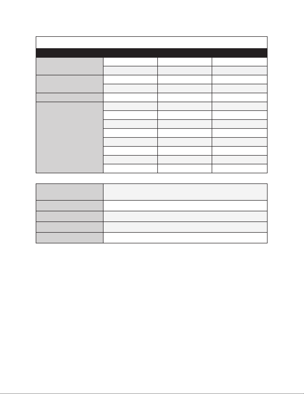
SPECIFICATIONS TABLE
Sizes Inner Diameter Outer Diameter Length
Receiving Cup
1-3/4” 2-1/8” 1/2”
1-13/16” 2-1/4” 7/16”
1-3/4” 2” 2-3/8”
Installing Tube
1-3/4” 2” 3”
Remover / Installer 3/4” 1-7/16” 1”
2” 2-1/4” 2”
2-1/4” 2-1/2” 1-1/2”
2-1/4” 2-1/2” 3/4”
2-1/4” 2-1/2” 2-3/4”
Receiving Tube
2-3/4” 3” 2-1/4”
2-7/16” 2-3/4” 2-1/4”
2-5/8” 2-7/8” 2-7/8”
2-3/16” 2-7/16” 3-3/16”
Applications
Most GM, Ford, and Dodge 2 & 4 WD Pickups, Vans,
and SUV’s through 1997
Compatibility Use with 3-In-1 Service Kit (Model 38335)
Material Forged, heat treated and machined carbon steel
Screw Plug Size 7/8” O.D. x 3” Long
Weight 12.8 Pounds
UNPACKING
When unpacking, check to make sure the parts shown on page 10 of this manual are
included. If any parts are missing or broken, please call Harbor Freight Tools at the
number shown at bottom of page as soon as possible.
SAVE THIS MANUAL
You will need this manual for the safety warnings and precautions, operating,
inspection, maintenance, and cleaning procedures. Keep your invoice with this
manual. Write the invoice number on the inside of the front cover. Keep this
manual and invoice in a safe and dry place for future reference.
For technical questions please call 1-800-444-3353Sku 66958
Page 2
Page 3

GENERAL SAFETY WARNINGS AND PRECAUTIONS
1. KEEP WORK AREA CLEAN AND DRY.
Cluttered, damp or wet work areas invite injuries.
2. KEEP CHILDREN AWAY FROM WORK AREA.
Do not allow children to handle this product.
3. STORE IDLE EQUIPMENT.
When not in use, tools and equipment should be stored in a dry location to inhibit
corrosion. Always lock up tools and equipment and keep out of reach of children.
4. DO NOT USE THIS PRODUCT IF UNDER THE INFLUENCE OF ALCOHOL OR
DRUGS. Read warning labels on prescriptions to determine if your judgment or
reexes are impaired while taking drugs. If there is any doubt, do not attempt to use
this product.
5. USE EYE PROTECTION.
Wear ANSI approved eye googles when using this product.
ANSI approved safety impact eye glasses are available from Harbor Freight Tools.
6. DRESS SAFELY.
Non-skid footwear or safety shoes should be used when working with this product.
Do not wear loose clothing or jewelry as they can become caught in moving parts.
Wear a protective hair covering to prevent long hair from becoming caught in
moving parts. If wearing a long-sleeve shirt, roll sleeves up above elbows.
7. INDUSTRIAL APPLICATIONS MUST FOLLOW OSHA REQUIREMENTS.
8. DO NOT OVERREACH. Keep proper footing and balance at all times to prevent
tripping, falling, back injury, etcetera.
9. STAY ALERT. Watch what you are doing at all times. Use common sense.
Do not use this product when you are tired or distracted from the job at hand.
10. CHECK FOR DAMAGED PARTS. Before using this product, carefully check that it
will operate properly and perform its intended function.
Check for damaged parts and any other conditions that may affect the operation of
this product. Replace damaged or worn parts immediately.
11. REPLACEMENT PARTS AND ACCESSORIES.
When servicing, use only identical replacement parts.
Only use accessories intended for use with this product.
Approved accessories are available from Harbor Freight Tools.
For technical questions please call 1-800-444-3353Sku 66958
Page 3
Page 4
12. MAINTAIN THIS PRODUCT WITH CARE.
This product contains or produces a chemical known to the State of California to
cause cancer and birth defects (or other reproductive harm).
(California Health & Safety Code 25249.5 et seq.)
Keep this tool clean and dry for better and safer performance.
13. USE THE RIGHT PRODUCT FOR THE RIGHT JOB. There are certain
applications for which this product was designed. Do not use small equipment,
tools or attachments to do the work of larger industrial equipment, tools or
attachments. Do not use this product for a purpose for which it was not intended.
14. PRIOR TO USING THIS PRODUCT, MAKE SURE TO READ AND
UNDERSTAND ALL INSTRUCTIONS AND SAFETY PRECAUTIONS AS
OUTLINED IN THE VEHICLES MANUFACTURER’S MANUALS.
15. NEVER WORK UNDERNEATH A VEHICLE WITHOUT USING ADDITIONAL
SAFETY SUPPORT DEVICES (I.E., JACK STANDS) TO SUPPORT THE WEIGHT
OF THE VEHICLE.
Read and understand all safety warnings and instructions provided in the instruction
manual of the vehicle as well as the jack stand being used to support the vehicle.
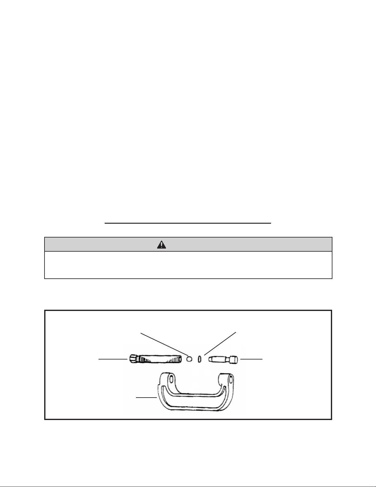
OPERATING INSTRUCTIONS
To Attach The Plug Bolt To The C-Frame:
STEEL BALL
(NOT PROVIDED)
FORCING
SCREW
(NOT PROVIDED)
C-FRAME (NOT PROVIDED)
WARNING
O-RING
(NOT PROVIDED)
PLUG BOLT (14)
(Included)
Figure A
For technical questions please call 1-800-444-3353Sku 66958
Page 4
Page 5

NOTE
This set is recommended for use with the 3-In-1 Service Kit
(Model 38335), which is available from Harbor Freight Tools.
Read and understand all safety warnings and instructions provided in
the instruction manual of the 3-In-1 Service Kit before using the kit.
All parts mentioned below are listed and shown on page 10 of this manual.
1. The illustration in Figure A depicts a disassembled C-Frame, a tool that is part of the
3-In-1 Service Kit (Model 38335) and recommended for use with this Master Ball
Joint Adapter Set. (See Figure A.)
2. To operate the Master Ball Joint Adapter Set, it will be necessary to attach the Plug
Bolt (part 14) contained in this Set to the C-Frame of the 3-In-1 Service Kit.
(See Figure A, and Parts List on Page 10.)
3. To do so, unscrew and remove the Forcing Screw, Steel Ball, and O-Ring from the
C-Frame. (See Figure A, and Parts List on Page 10.)
4. Make sure the Steel Ball and O-Ring remain inside the Forcing Screw.
Then, insert the Plug Bolt (part 14) into the Forcing Screw, if required.
5. Screw the threaded end of the Forcing Screw, with its Steel Ball, O-Ring, and
attached Plug Bolt (part 14) back into the threaded end of the C-Frame toward the
unthreaded hole of the C-Frame. (See Figure A, and Parts List on Page 10.)
To Remove A Ball Joint:
NOTE: The following instructions apply to most GM, Ford, and Dodge 2 and 4 wheel
drive pickups, vans, and SUV’s through 1997 (see charts on pages 7 through 9).
The instructions are intended to illustrate the process in general terms, not to be
specic to any one make/model vehicle. A combination of Receiving Tubes
(parts 1, 2, 3, 4, 5, 6, 10, 11), Receiving Cups (parts 7 & 12), and Installing Tubes
(parts 8 & 9), will be necessary for different vehicles.
1. Remove all attaching hardware from the ball joint.
2. Mount the Remover/Installer (part 13) on the Forcing Screw assembly so that the
larger diameter portion of the Remover/Installer faces the threaded hole of the
C-Frame, and the smaller diameter portion faces the unthreaded side of the ball joint.
(See Figure B, and Parts List on Page 10.)
3. Mount the proper size Receiver Tube (part 1, 2, 3, 4, 5, 6, 10, or 11)
over the threaded side of the ball joint.
For technical questions please call 1-800-444-3353Sku 66958
Page 5
Page 6

RECEIVER TUBE
(1, 2, 3, 4, 5, 6, 10, 11)
REMOVER/INSTALLER (13)
PLUG BOLT (14)
C-FRAME
FORCING SCREW
Figure B
(See Figure B, and Parts list on Page 10.)
4. Align the mounted Remover/Installer (part 13), ball joint, and Reciever Tube
(part 1, 2, 3, 4, 5, 6, 10, or 11) to allow removal of the ball joint.
5. Using a wrench, turn the Forcing Screw assembly clockwise to remove the ball joint.
To Install A Ball Joint:
(See Figure B, and Parts List on Page 10.)
1. Mount the Remover/Installer (part 13) on the Forcing Screw assembly so that the
larger diameter portion of the Remover/Installer faces the threaded hole of the CFrame, and the smaller diameter portion faces the unthreaded side of the ball joint.
2. Place the mounted Remover/Installer (part 13) on the unthreaded side of the
ball joint.
3. Align the mounted Remover/Installer (part 13), ball joint, and proper size Reciever
Tube (part 1, 2, 3, 4, 5, 6, 10, or 11) to allow installation of the ball joint.
4. Using a wrench, turn the Forcing Screw assembly clockwise to install the ball joint.
For technical questions please call 1-800-444-3353Sku 66958
Page 6
Page 7

BALL JOINT ADAPTER APPLICATIONS
U = Upper, L = Lower, R = Remove, I = Install Part Numbers Below Illustrated on Page 10
Upper/
Lower
DODGE® / CHRYSLER® / PLYMOUTH
L 1987-97 2WD Dakota
Vehicle
®
L 1972-93 1/2-, 3/4-Ton 2WD Pickup R I I R
L 1974-93 1/2-Ton 2WD Ramcharger
®
L 1979-97 1/2-, 3/4-, 1-Ton 2WD Van R I I R
L 1972-93 2WD 3/4-, 1-Ton Pickup I R
L 1979-97 1-Ton 2WD Van I R
L 1984-96 Caravan®, Voyager®, Town & Country
®
U 1994-97 2WD 1/2-, 3/4-, 1-Ton Pickup (IFS) I
L 1994-97 2WD 1/2-, 3/4-, 1-Ton Pickup (IFS) I
U 1994-97 2WD 1-Ton Solid Axle I I
L 1994-97 2WD 1-Ton Solid Axle I I R I
U 1994-97 3/4-, 1-Ton Dana® 60 Axle, 4WD I I
L 1994-97 3/4-, 1-Ton Dana® 60 Axle, 4WD I I R I
L U 1994-97 1/2-, 3/4-Ton Dana® 44 Axle, 4WD R I I R
L 1972-93 1/2-, 3/4-, 1-Ton 4WD & Ramcharger
U 1972-93 1/2-, 3/4-, 1-Ton 4WD & Ramcharger
®
®
1 2 3 4 5 6 7 8 9 10 11 12 13 14
®
R I I R
R I I R
R
R I I R
I I R
JEEP
L U 1993-97 2WD Grand Cherokee
®
L U 1993-95 4WD Grand Cherokee®, Grand Wagoneer
U 1987-97 4WD Wrangler
U 1984-95 4WD Cherokee®, Wagoneer
®
®
L 1990-97 2WD Cherokee®, Comanche®, Wagoneer
L 1990-97 4WD Wrangler
L 1990-95
2WD & 4WD Cherokee®, Comanche
®
®
,
Wagoneer
U 1984-97 2WD Cherokee®, Comanche®, Wagoneer
L 1984-89 2WD Cherokee®, Comanche®, Wagoneer
L 1987-89 4WD Wrangler
®
L 1984-89 4WD Cherokee®, Comanche®, Wagoneer
L U 1984-92 Full Size 4WD Grand Wagoneer
L U 1972-88
4WD Truck, CJ
®
,
Full Size Cherokee
®
®
,
Wagoneer
1 2 3 4 5 6 7 8 9 10 11 12 13 14
R I I R
®
®
®
®
®
®
®
R I I R
R I I R
R I I R
R I I R
R I I R
R I I R
R I I R
R I I R I
R I I R I
R I I R I
I I R
I I R
For technical questions please call 1-800-444-3353Sku 66958
Page 7
Page 8

BALL JOINT ADAPTER APPLICATIONS
U = Upper, L = Lower, R = Remove, I = Install Part Numbers Below Illustrated on Page 10
Upper/
Lower
FORD
L 1986-97 Aerostar I
U 1987-88 2WD Bronco II I
U 1989-90 2WD Bronco II I I
L 1989-90 2WD Bronco II I
U 1991-94 2WD Explorer I I
L 1991-94 2WD Explorer I
U 1983-88 2WD Ranger I
U 1989-97 2WD Ranger I I
U 1987-96 2WD 1/2-Ton Pickup R I I R
L 1997 2WD & 4WD1/2-Ton Pickup I R I
U 1987-97 2WD 3/4-, 1-Ton Pickup R I I R
U 1981-86 2WD 1/2-Ton Pickup I
L 1981-86 2WD 1/2-Ton Pickup I I R
U 1990 4WD Bronco II with Dana 28 I
U 1984-89 4WD Bronco II I
L U 1980-96 4WD Bronco I I R
U 1991-94 4WD Explorer with Dana 28 I
U 1991-97 4WD Ranger with Dana 28 I
U 1983-89 4WD Ranger I
L U 1980-96 4WD Bronco I I R
L 1981 4WD 1-Ton (3800 axle) I I R
L 1980-96 4WD 1/2-, 3/4-Ton I I R
L 1987-97 2WD 1/2-, 3/4-Ton I I R I
U 1992-97 2WD 1/2-, 3/4-, 1-Ton Van R I R
L 1992-97 2WD 1/2-Ton Van I
L 1992-97 2WD 3/4-, 1-Ton Van R I
L 1984-89 4WD Bronco II I
L 1990 4WD Bronco II with Dana 28 I
L U 1990 4WD Bronco II with Dana 35 I
U 1991-93 4WDExplorer with Dana 35 I
U 1990-93 4WD Ranger with Dana 35 I
U 1992-97 4WD 1-Ton I I R
U 1980-96 4WD 1/2-,3/4-, 1-Ton (IFS) I I R
L U 1993-94 4WD Explorer with Dana 35 I
L U 1993-97 4WD Ranger with Dana 35 I
L 1996-97 4WD 1-Ton with Solid Axle I I R I
L 1980-95 4WD 3/4-, 1-Ton Spindle I I R I
Vehicle
1 2 3 4 5 6 7 8 9 10 11 12 13 14
For technical questions please call 1-800-444-3353Sku 66958
Page 8
Page 9

BALL JOINT ADAPTER APPLICATIONS
U = Upper, L = Lower, R = Remove, I = Install Part Numbers Below Illustrated on Page 10
Upper/
Lower
GENERAL MOTORS
L 1982-97 2WD S-10 Blazer, Jimmy, Pickup I R I
L 1985-97 Astro Safari Van I
L 1973-95 2WD 1/2-, 3/4-Ton G Van I
L 1996-97 4WD 1/2-, 3/4-, 1-Ton R I I
Vehicle
INSPECTION AND MAINTENANCE
Before each use, inspect the general condition of the Master Ball Joint Adapter set.
Check for cracks , breaks, or bends in the tool, and any other condition that may
affect its safe operation. If a problem occurs with the tool, immediately discontinue
its use and have the problem corrected before further use.
Do not use damaged equipment.
1 2 3 4 5 6 7 8 9 10 11 12 13 14
CLEANING
Wipe with a damp cloth. You may use a mild detergent or mild solvent.
PLEASE READ THE FOLLOWING CAREFULLY
THE MANUFACTURER AND/OR DISTRIBUTOR HAS PROVIDED THIS MANUAL AS
A REFERENCE TOOL ONLY. NEITHER THE MANUFACTURER NOR DISTRIBUTOR
MAKES ANY REPRESENTATION OR WARRANTY OF ANY KIND TO THE BUYER
THAT HE OR SHE IS QUALIFIED TO MAKE ANY REPAIRS TO THE PRODUCT OR
THAT HE OR SHE IS QUALIFIED TO REPLACE ANY PARTS OF THE PRODUCT. IN
FACT, THE MANUFACTURER AND/OR DISTRIBUTOR EXPRESSLY STATES THAT
ALL REPAIRS AND PARTS REPLACEMENTS SHOULD BE UNDERTAKEN BY
CERTIFIED AND LICENSED TECHNICIANS AND NOT BY THE BUYER. THE BUYER
ASSUMES ALL RISK AND LIABILITY ARISING OUT OF HIS OR HER REPAIRS TO
THE ORIGINAL PRODUCT OR REPLACEMENT PARTS THERETO, OR ARISING
OUT OF HIS OR HER INSTALLATION OF REPLACEMENT PARTS THERETO.
For technical questions please call 1-800-444-3353Sku 66958
Page 9
Page 10

PARTS LIST
Part Number Description Part Number Description
1 Receiving Tube 9 Installing Tube
2 Receiving Tube 10 Receiving Tube
3 Receiving Tube 11 Receiving Tube
4 Receiving Tube 12 Receiving Cup
5 Receiving Tube 13 Remover / Installer
6 Receiving Tube 14 Plug Bolt
7 Receiving Cup 15 Carrying Case (Not Shown)
8 Installing Tube
Quantity = One Each
NOTE
Some parts are listed and shown for illustration purposes only, and are not available individually as replacement parts.
For technical questions please call 1-800-444-3353Sku 66958
Page 10
Page 11

LIMITED 90 DAY WARRANTY
Harbor Freight Tools Co. makes every effort to assure that its products meet high
quality and durability standards, and warrants to the original purchaser that this product
is free from defects in materials and workmanship for the period of 90 days from the date
of purchase. This warranty does not apply to damage due directly or indirectly, to misuse,
abuse, negligence or accidents, repairs or alterations outside our facilities, criminal activity,
improper installation, normal wear and tear, or to lack of maintenance. We shall in no event
be liable for death, injuries to persons or property, or for incidental, contingent, special
or consequential damages arising from the use of our product. Some states do not allow
the exclusion or limitation of incidental or consequential damages, so the above limitation
of exclusion may not apply to you. THIS WARRANTY IS EXPRESSLY IN LIEU OF ALL
OTHER WARRANTIES, EXPRESS OR IMPLIED, INCLUDING THE WARRANTIES OF
MERCHANTABILITY AND FITNESS.
To take advantage of this warranty, the product or part must be returned to us with
transportation charges prepaid. Proof of purchase date and an explanation of the com-
plaint must accompany the merchandise. If our inspection veries the defect, we will either
repair or replace the product at our election or we may elect to refund the purchase price
if we cannot readily and quickly provide you with a replacement. We will return repaired
products at our expense, but if we determine there is no defect, or that the defect resulted
from causes not within the scope of our warranty, then you must bear the cost of returning
the product.
This warranty gives you specic legal rights and you may also have other rights
which vary from state to state.
3491 Mission Oaks Blvd. • PO Box 6009 • Camarillo, CA 93011 • (800) 444-3353
For technical questions please call 1-800-444-3353Sku 66958
Page 11
 Loading...