

Page 1
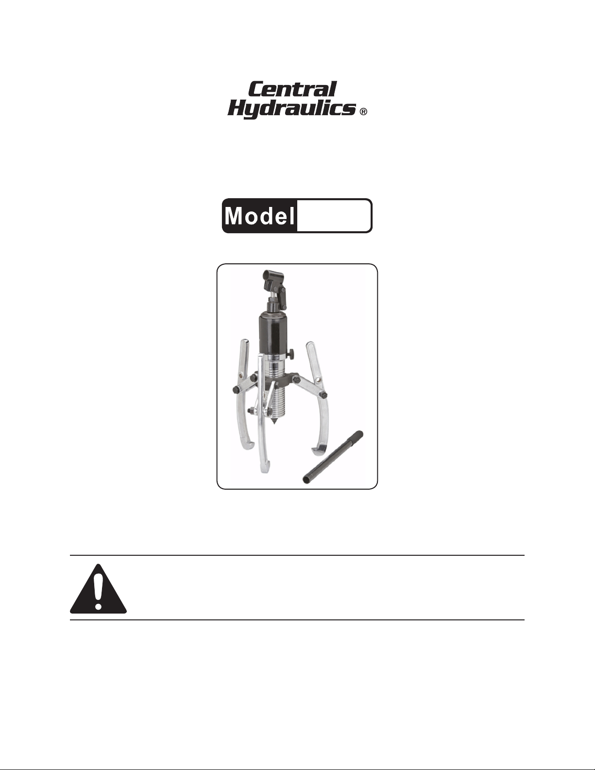
12 TON HYDRAULIC GEAR
PULLER KIT
66657
SET UP AND OPERATING INSTRUCTIONS
Distributed exclusively by Harbor Freight Tools®.
3491 Mission Oaks Blvd., Camarillo, CA 93011
Visit our website at: http://www.harborfreight.com
Read this material before using this product.
Failure to do so can result in serious injury.
SAVE THIS MANUAL.
Copyright© 2008 by Harbor Freight Tools®. All rights reserved. No portion of this manual or any artwork
contained herein may be reproduced in any shape or form without the express written consent of
Harbor Freight Tools. Diagrams within this manual may not be drawn proportionally. Due to continuing
improvements, actual product may differ slightly from the product described herein. Tools required for
assembly and service may not be included.
For technical questions or replacement parts, please call 1-800-444-3353.
Page 2
SAVE THIS MANUAL
Keep this manual for the safety warnings and precautions, assembly, operating, inspection, maintenance and cleaning
procedures. Write the product’s serial
number in the back of the manual near the
assembly diagram (or month and year of
purchase if product has no number). Keep
this manual and the receipt in a safe and
dry place for future reference.
IMPORTANT SAFETY
INFORMATION
In this manual, on the labeling,
and all other information provided with this product:
NOTICE is used to
address practices
not related to personal injury.
CAUTION, without
the safety alert
symbol, is used to address
practices not related to
personal injury.
General Tool Safety Warnings
WARNING Read all safety
warnings and instructions.
Failure to follow the warnings and
instructions may result in serious
injury.
Save all warnings and
instructions for future reference.
This is the safety alert
symbol. It is used to alert
you to potential personal
injury hazards. Obey all
safety messages that
follow this symbol to avoid
possible injury or death.
DANGER indicates
a hazardous
situation which, if not
avoided, will result in death or
serious injury.
WARNING
indicates a
hazardous situation which, if
not avoided, could result in
death or serious injury.
CAUTION, used
with the safety
alert symbol, indicates a
hazardous situation which, if
not avoided, could result in
minor or moderate injury.
Work area safety1.
Keep work area clean and well lit. a.
Cluttered or dark areas invite accidents.
Keep children and bystanders b.
away while operating the Gear
Puller. Distractions can cause you to
lose control.
Personal safety2.
Stay alert, watch what you are do-a.
ing and use common sense when
operating the Gear Puller. Do not
use while you are tired or under
the inuence of drugs, alcohol or
medication. A moment of inattention
while operating the tool may result in
serious personal injury.
Use personal protective equip-b.
ment. Always wear eye protection.
Do not overreach. Keep proper c.
footing and balance at all times.
This enables better control of the tool
in unexpected situations.
SKU 66657 For technical questions, please call 1-800-444-3353. Page 2
Page 3
Dress properly. Do not wear loose d.
clothing or jewelry. Keep your
hair, clothing and gloves away
from moving parts. Loose clothes,
jewelry or long hair can be caught in
moving parts.
Only use safety equipment that e.
has been approved by an appropriate standards agency. Unapproved
safety equipment may not provide
adequate protection. Eye protection
must be ANSI-approved and breathing protection must be NIOSH-ap-
proved for the specic hazards in the
work area.
Gear Puller use and care3.
Do not force the Gear Puller. Use a.
the correct tool for your application. The correct tool will do the job
better and safer at the rate for which
it was designed.
Store idle tools out of the reach of b.
children and do not allow persons
unfamiliar with the Gear Puller or
these instructions to operate the
tool. Tools are dangerous in the
hands of untrained users.
Maintain the Gear Puller. Check c.
for misalignment or binding of
moving parts, breakage of parts
and any other condition that may
affect the tool’s operation. If damaged, have the tool repaired before
use. Many accidents are caused by
poorly maintained tools.
Use the Gear Puller and any acces-d.
sories in accordance with these instructions, taking into account the
working conditions and the work
to be performed. Use of this tool
for operations different from those
intended could result in a hazardous
situation.
Service4.
Have your Gear Puller serviced a.
by a qualied repair person using
only identical replacement parts.
This will ensure that the safety of the
tool is maintained.
Hydraulic Gear Puller Safety
Warnings
Do not exceed 12 ton (24,000 lbs.) 1.
Gear Puller capacity.
Read and understand instruction 2.
manual.
Always wear ANSI-approved safety 3.
goggles.
Maintain labels and nameplates on 4.
the tool. These carry important safety
information. If unreadable or missing, contact Harbor Freight Tools for a
replacement.
This product is not a toy. Keep it out 5.
of reach of children.
The warnings, precautions, and in-6.
structions discussed in this instruction
manual cannot cover all possible conditions and situations that may occur.
It must be understood by the operator
that common sense and caution are
factors which cannot be built into this
product, but must be supplied by the
operator.
SAVE THESE
INSTRUCTIONS.
SKU 66657 For technical questions, please call 1-800-444-3353. Page 3
Page 4

SPECIFICATIONS
Assembly
Pressure Capacity 12 ton (24,000 lbs.)
Type
Size Capacity 9 ¾” max. diameter
3 jaw puller with
hydraulic cylinder
UNPACKING
Puller Unit
Puller
Sleeve (6)
Handle (11)
When unpacking, make sure that the
above parts are included and that they are
undamaged. If any parts are missing or
broken, please call Harbor Freight Tools
at the number shown on the cover of this
manual as soon as possible.
Bolt, Washer,
Nut sets (19)
Connector
Plates (5)
Jaws (1)
Thread the Puller Sleeve (6) onto 1.
the Puller Unit about half way up the
threaded section of the Puller Unit.
Determine if the best grip on the part 2.
to be pulled is from the outside or the
inside. The hooks on the Jaws (1)
face inward when gripping the part
from the outside. They face outward
when gripping the part from the inside.
Determine whether to use the upper 3.
or lower holes in the Jaws. The upper
holes (nearest the end of the Jaw),
are for larger items, approximately
6” - 9” in diameter. The lower holes
(closest to the center of the Jaw), are
for items smaller than 6”.
Pump Handle Socket (12)
Puller
Sleeve (6)
Connector
Plates (5)
Bolt/Washer/Nut Sets (19)
Handle (11)
INSTRUCTIONS FOR
PUTTING INTO USE
Read the ENTIRE IMPORTANT
SAFETY INFORMATION
section at the beginning of this
manual including all text under
subheadings therein before set
up or use of this product.
Note: For additional information regarding
the parts listed in the following pages,
refer to the Assembly Diagram near
the end of this manual.
4. Assemble each of the three Jaws
onto the Puller Sleeve (6) using two
Connector Plates (5) and two Bolt
Sets (19) as shown in the photo
above.
Insert the Handle (11) into the Pump 5.
Handle Socket (12)
SKU 66657 For technical questions, please call 1-800-444-3353. Page 4
Jaw (1)
Page 5

Functions
The tool is designed to pull items
such as bearings, pulleys, and chucks
from shafts. The Jaws (1) grip the item
from the inside or outside, whichever offers a better grip. The Piston (8) will push
on the central shaft while the Jaws pull
away. This will remove the item from the
shaft by pulling it straight out evenly, without hammering or binding from pulling at
an angle.
OPERATING INSTRUCTIONS
Read the ENTIRE IMPORTANT
SAFETY INFORMATION
section at the beginning of this
manual including all text under
subheadings therein before set
up or use of this product.
CAUTION! This tool will deliver up to
12 tons (24,000 lbs.) of pulling
force. DO NOT use this tool on
any work piece which cannot
withstand this amount of
pressure.
Work Piece and Work Area Set Up
Designate a work area that is clean 1.
and well-lit. To prevent injury and/or
distraction, the work area must not
allow access by children or pets.
overtighten, as this will damage the
seal.
Place the Jaws (1) around (or in) the 2.
item to be pulled. Be sure they will
have a rm grip.
While holding the Jaws in place, 3.
rotate the Puller Unit in the Puller
Sleeve (6), until the end of the Piston
(8) contacts the work piece.
Pump the Handle (11) up and down 4.
to force the Piston down, causing the
Jaws to pull upward.
Continue pumping the Handle, be-5.
ing sure the Jaws stay in place on
the object and the object is not being
damaged.
In most cases, a certain amount of 6.
pressure will build up, and the Gear
Puller will suddenly loosen and release. Be sure the Gear Puller does
not fall when loosened.
When nished, open the Return Valve 7.
(7) by turning it 1 turn counter clockwise (do not remove), and remove
the Gear Puller form the work piece.
To prevent accidents, clean, then 8.
store the Gear Puller in it’s case,
indoors out of children’s reach.
There must not be hazardous ob-2.
jects, such as utility lines or foreign
objects, nearby that will present a
hazard while working.
General Operating Instructions
Close the Return Valve (7) by turning 1.
it clockwise until hand tight. Do not
SKU 66657 For technical questions, please call 1-800-444-3353. Page 5
Page 6

MAINTENANCE AND
SERVICING
Procedures not specically
explained in this manual
must be performed only by a
qualied technician.
TO PREVENT
SERIOUS INJURY
FROM TOOL FAILURE:
Do not use damaged
equipment. If abnormal noise
or vibration occurs, have the
problem corrected before
further use.
Cleaning, Maintenance, and
Lubrication
BEFORE EACH USE,1. inspect the
general condition of the Gear Puller.
Check for loose screws, misalignment
or binding of moving parts, cracked or
broken parts, and any other condition
which may affect its safe operation.
Note: This step should ONLY be per-
formed by a qualied technician.
Remove the Pump Handle Socket a.
(12) and Pump Axle (10).
Using an oil gun, pour oil slowly into b.
the pump housing to overowing.
Reassemble, and wipe excess oil c.
from the tool.
AFTER USE,2. clean external surfaces
with clean cloth.
Lightly oil the threads and pivoting 3.
joints periodically to keep them operating smoothly.
Keep Piston (8) in the fully retracted 4.
position while in storage to prevent
rust or damage.
If rust appears on any part of the tool, 5.
remove it with a penetrating oil.
If the tool fails to perform adequately, 6.
the oil level in the system should be
checked and air purged from the
system.
SKU 66657 For technical questions, please call 1-800-444-3353. Page 6
Page 7

PLEASE READ THE FOLLOWING CAREFULLY
THE MANUFACTURER AND/OR DISTRIBUTOR HAS PROVIDED THE PARTS LIST AND ASSEMBLY
DIAGRAM IN THIS MANUAL AS A REFERENCE TOOL ONLY. NEITHER THE MANUFACTURER OR
DISTRIBUTOR MAKES ANY REPRESENTATION OR WARRANTY OF ANY KIND TO THE BUYER THAT
HE OR SHE IS QUALIFIED TO MAKE ANY REPAIRS TO THE PRODUCT, OR THAT HE OR SHE IS
QUALIFIED TO REPLACE ANY PARTS OF THE PRODUCT. IN FACT, THE MANUFACTURER AND/
OR DISTRIBUTOR EXPRESSLY STATES THAT ALL REPAIRS AND PARTS REPLACEMENTS SHOULD
BE UNDERTAKEN BY CERTIFIED AND LICENSED TECHNICIANS, AND NOT BY THE BUYER. THE
BUYER ASSUMES ALL RISK AND LIABILITY ARISING OUT OF HIS OR HER REPAIRS TO THE
ORIGINAL PRODUCT OR REPLACEMENT PARTS THERETO, OR ARISING OUT OF HIS OR HER
INSTALLATION OF REPLACEMENT PARTS THERETO.
SKU 66657 For technical questions, please call 1-800-444-3353. Page 7
Page 8

PARTS LIST
PARTS LIST
Part Description Qty.
1 Jaw 3
2 Piston 1
3 Spring 1
4 Oil Cylinder 1
5 Connector Plate 6
6 Puller Sleeve 1
7 Return Valve 1
8 Piston 1
9 Outer Sleeve 1
10 Pump Axle 1
ASSEMBLY DIAGRAM
Part Description Qty.
11 Handle 1
12 Pump Handle Socket 1
13 Connecting Rod 2
14 Hanger Foot 1
15 Pump Core 1
16 Oil Reservoir 1
17 Oil Seal 1
18 Screw 1
19 Bolt/Washer/Nut Set 6
19
Record Product’s Serial Number Here:
Note: If product has no serial number, record month and year of purchase instead.
Note: Some parts are listed and shown for illustration purposes only, and are not avail-
able individually as replacement parts.
SKU 66657 For technical questions, please call 1-800-444-3353. Page 8
 Loading...