

Page 1

10” HEAVY-DUTY 15 AMP
TABLE SAW
66630
SET UP AND OPERATING INSTRUCTIONS
Distributed exclusively by Harbor Freight Tools®.
3491 Mission Oaks Blvd., Camarillo, CA 93011
Visit our website at: http://www.harborfreight.com
Read this material before using this product.
Failure to do so can result in serious injury.
SAVE THIS MANUAL.
Copyright© 2008 by Harbor Freight Tools®. All rights reserved. No portion of this manual or any artwork
contained herein may be reproduced in any shape or form without the express written consent of
Harbor Freight Tools. Diagrams within this manual may not be drawn proportionally. Due to continuing
improvements, actual product may differ slightly from the product described herein. Tools required for
assembly and service may not be included.
For technical questions or replacement parts, please call 1-800-444-3353.
Page 2

SAVE THIS MANUAL
Keep this manual for the safety warnings and precautions, assembly, operating, inspection, maintenance and cleaning
procedures. Write the product’s serial
number in the back of the manual near the
assembly diagram (or month and year of
purchase if product has no number). Keep
this manual and the receipt in a safe and
dry place for future reference.
IMPORTANT SAFETY
INFORMATION
In this manual, on the labeling,
and all other information provided with this product:
This is the safety alert
symbol. It is used to alert
you to potential personal
injury hazards. Obey all
safety messages that
follow this symbol to avoid
possible injury or death.
NOTICE is used to
address practices
not related to personal injury.
CAUTION, without
the safety alert
symbol, is used to address
practices not related to
personal injury.
General Tool Safety Warnings
WARNING Read all safety
warnings and instructions.
Failure to follow the warnings and
instructions may result in electric
shock, re and/or serious injury.
Save all warnings and
instructions for future reference.
KEEP GUARDS IN PLACE and in 1.
working order.
REMOVE ADJUSTING KEYS AND 2.
WRENCHES. Form habit of checking to see that keys and adjusting
wrenches are removed from tool
before turning it on.
DANGER indicates
a hazardous
situation which, if not
avoided, will result in death or
serious injury.
WARNING
indicates a
hazardous situation which, if
not avoided, could result in
death or serious injury.
CAUTION, used
with the safety
alert symbol, indicates a
hazardous situation which, if
not avoided, could result in
minor or moderate injury.
SKU 66630 For technical questions, please call 1-800-444-3353. Page 2
KEEP WORK AREA CLEAN. Clut-3.
tered areas and benches invite accidents.
DON’T USE IN DANGEROUS EN-4.
VIRONMENT. Don’t use power tools
in damp or wet locations, or expose
them to rain. Keep work area well
lighted.
KEEP CHILDREN AWAY. All visitors 5.
should be kept safe distance from
work area.
MAKE WORKSHOP KID PROOF 6.
with padlocks, master switches, or by
removing starter keys.
Page 3

DON’T FORCE TOOL. It will do the 7.
job better and safer at the rate for
which it was designed.
USE RIGHT TOOL. Don’t force tool 8.
or attachment to do a job for which it
was not designed.
glasses only have impact resistant
lenses, they are NOT safety glasses.
SECURE WORK. Use clamps or a 12.
vise to hold work when practical. It’s
safer than using your hand and it
frees both hands to operate tool.
RECOMMENDED MINIMUM WIRE
GAUGE FOR EXTENSION CORDS
(120 VOLT)
NAMEPLATE
AMPERES
(at full load)
0 – 6 18 16 16 14
6.1 – 10 18 16 14 12
10.1 – 12 16 16 14 12
12.1 – 16 14 12 Do not use.
EXTENSION CORD
LENGTH
25’ 50’ 100’ 150’
TABLE A
USE PROPER EXTENSION CORD. 9.
Make sure your extension cord is
in good condition. When using an
extension cord, be sure to use one
heavy enough to carry the current
your product will draw. An undersized
cord will cause a drop in line voltage
resulting in loss of power and overheating. Table A shows the correct
size to use depending on cord length
and nameplate ampere rating. If in
doubt, use the next heavier gage.
The smaller the gage number, the
heavier the cord.
WEAR PROPER APPAREL. Do not 10.
wear loose clothing, gloves, neckties, rings, bracelets, or other jewelry
which may get caught in moving
parts. Nonslip footwear is recommended. Wear protective hair covering to contain long hair.
ALWAYS USE SAFETY GLASSES. 11.
Also use face or dust mask if cutting
operation is dusty. Everyday eye-
DON’T OVERREACH. Keep proper 13.
footing and balance at all times.
MAINTAIN TOOLS WITH CARE. 14.
Keep tools sharp and clean for best
and safest performance. Follow
instructions for lubricating and changing accessories.
DISCONNECT TOOLS before ser-15.
vicing; when changing accessories,
such as blades, bits, cutters, and the
like.
REDUCE THE RISK OF UNINTEN-16.
TIONAL STARTING. Make sure
switch is in off position before plugging in.
USE RECOMMENDED ACCESSO-17.
RIES. Consult the owner’s manual for
recommended accessories. The use
of improper accessories may cause
risk of injury to persons.
NEVER STAND ON TOOL. Serious 18.
injury could occur if the tool is tipped
or if the cutting tool is unintentionally
contacted.
CHECK DAMAGED PARTS. Before 19.
further use of the tool, a guard or
other part that is damaged should
be carefully checked to determine
that it will operate properly and perform its intended function – check for
alignment of moving parts, binding
of moving parts, breakage of parts,
mounting, and any other conditions
that may affect its operation. A guard
SKU 66630 For technical questions, please call 1-800-444-3353. Page 3
Page 4

or other part that is damaged should
be properly repaired or replaced.
DIRECTION OF FEED. Feed work 20.
into a blade or cutter against the
direction of rotation of the blade or
cutter only.
NEVER LEAVE TOOL RUNNING 21.
UNATTENDED. TURN POWER OFF.
Don’t leave tool until it comes to a
complete stop.
Table Saw Safety Warnings
For Your Own Safety Read Instruction
Manual Before Operating Saw
Wear eye protection.1.
Use saw-blade guard and spreader 2.
for every operation for which it can be
used, including all through sawing.
Keep hands out of the line of saw 3.
blade.
Use a push-stick when required.4.
Through-sawing – A cut made from b.
one side of a board to the opposite
side, without stopping.
Ripcut or Ripping - A cut made paral-c.
lel to (along with) the grain of the
wood.
Crosscut or Crosscutting - A cut d.
made perpendicular (at a 90° angle)
to the grain of the wood.
Push-stick – A narrow strip of wood e.
or other soft material with a notch
cut into one end and which is used
to push short pieces of material
through saws. It provides a safe
distance between the hands and the
cutting tool. Must be narrower than
the cut width to prevent contact with
the blade.
Freehand – Feeding a workpiece f.
through the saw without using a
fence or guided support to guide it.
NOT A SAFE METHOD.
Kerf – The gap made by the saw in g.
the workpiece.
Know how to reduce risk of kickback.5.
Do not perform any operation free-6.
hand.
Never reach around or over saw 7.
blade.
Make sure the workpiece is support-8.
ed at all times while sawing. Use a
roller stand (not provided) with larger
workpieces if necessary.
To properly understand all safety 9.
warnings, be familiar with the following safety terms and equipment:
Featherboard – A block with “ngers“ a.
that hold the workpiece against the
fence while sawing.
SKU 66630 For technical questions, please call 1-800-444-3353. Page 4
Kickback – A sudden reaction to a h.
pinched, bound, or misaligned blade,
causing an uncontrolled workpiece
to lift up and out of the saw toward
the operator.
Spreader – A metal plate that fol-i.
lows the saw blade to keep the kerf
(gap) from closing on the saw blade.
Spreaders, except riving knives,
must be aligned to the blade after
blade adjustment to prevent binding.
Riving Knife – A spreader mounted j.
on the same mechanism as the
blade. Generally more effective than
simple spreaders.
As noted previously, 10. Kickback is a
sudden reaction to a pinched, bound,
or misaligned blade, causing an un-
Page 5

controlled workpiece to lift up and out
of the saw toward the operator.
Kickback is usually a result of tool
misuse and can be limited or avoided
by following the precautions below:
movable guard does not move freely
and close instantly. Make sure any
movable guard does not touch the
blade in all angles, depths of cut, and
positions.
Fence must be completely parallel •
to the saw blade.
Workpiece must be free from aws •
(such as loose knots) and from
foreign objects (such as nails and
screws).
Support large workpieces along •
their entire length. Large workpieces tend to bend, grabbing the blade.
Do not use a dull, damaged, or •
pitch-covered blade.
Do not use fence as a guide when •
crosscutting.
Do not ripcut a twisted or warped •
workpiece, or workpiece without
straight edge to guide along fence.
Maintain control of the workpiece. •
Do not allow the workpiece to rest
against the moving blade without
holding onto it.
If the blade binds or a cut is inter-•
rupted, turn off the power switch
and hold the workpiece still until the
blade stops. Correct the cause of
blade binding before proceeding.
Before continuing an unnished •
cut, center the blade in the pre-cut
kerf and check that the saw teeth
are not engaged into the workpiece
before turning on the saw.
Push the wood stock past the blade •
prior to release.
Check guards for proper operation 11.
with saw disconnected from power
before each use. Do not disable any
guard. Do not operate saw if any
Keep the guard in place while 12.
through-sawing. Verify that the
spreader lines up with the blade to
prevent binding.
Construct a Push Stick out of Wood 13.
according to the guidelines on the following page The use of accessories
or attachments not recommended by
the manufacturer may result in a risk
of injury to persons. See next page
for Push Stick Features and Functions.
SKU 66630 For technical questions, please call 1-800-444-3353. Page 5
Page 6
Handle Notch
Must be far •
enough down
the stick to allow
a comfortable and
rm grip.
Must be deep enough •
to prevent hand from
slipping down the
stick.
Do not cut more than •
halfway into the stick
to prevent weakening.
Corners may be •
rounded to increase
comfort.
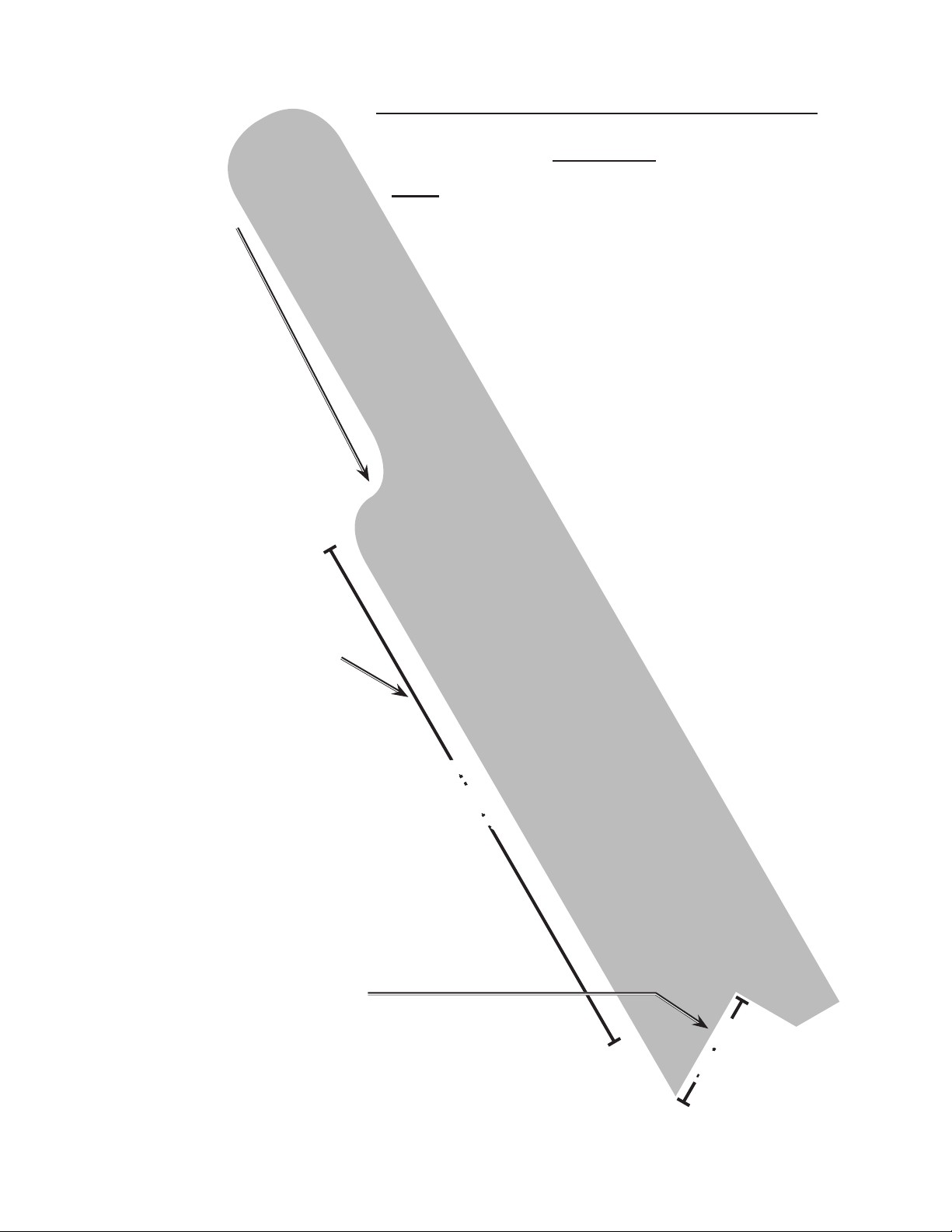
Essential Straight Push-stick Features and
Functions
Note: Straight style (traditional) stick shown. A dif-
ferent stick design may be used if it properly
protects against all hazards.
Diagram not to scale.
Push sticks must be made from sturdy, defect-free, •
plywood or normal wood to prevent unexpected
breakage. Material must be at least 1/4” thick ,but
no thicker than the nished wood.
Inspect push stick before use and do not use a •
damaged or deteriorated push stick.
Push stick dimensions will vary depending •
on the application and user.
Stick Length
Must be long enough •
to prevent accidental
blade contact.
At least 6” from end of •
handle to closest part
of notch.
Notch
Must be right angle cut 30°-40° from the angle of the stick to •
keep hands out of the line of the blade.
The lower lip of the notch must be no longer than the workpiece •
is thick.
At Least 6”
Less than
workpiece
thickness
SKU 66630 For technical questions, please call 1-800-444-3353. Page 6
Page 7

When servicing use only identical 14.
replacement parts.
Only use safety equipment that has 15.
been approved by an appropriate
standards agency. Unapproved
safety equipment may not provide
adequate protection. Eye protection
must be ANSI-approved and breathing protection must be NIOSH-ap-
proved for the specic hazards in the
work area.
Industrial applications must follow 16.
OSHA guidelines.
Maintain labels and nameplates on 17.
the tool. These carry important safety
information. If unreadable or missing, contact Harbor Freight Tools for a
replacement.
Avoid unintentional starting. Prepare 18.
to begin work before turning on the
tool.
People with pacemakers should 19.
consult their physician(s) before use.
Electromagnetic elds in close proximity to heart pacemaker could cause
pacemaker interference or pacemaker failure. In addition, people with
pacemakers should:
• Avoid operating alone.
• Do not use with power switch locked
on.
• Properly maintain and inspect to
avoid electrical shock.
• Any power cord must be properly
grounded. Ground Fault Circuit Interrupter (GFCI) should also be implemented – it prevents sustained electrical shock.
Some dust created by power sand-20.
ing, sawing, grinding, drilling, and
other construction activities, contains
chemicals known [to the State of California] to cause cancer, birth defects
or other reproductive harm. Some
examples of these chemicals are:
• Lead from lead-based paints
• Crystalline silica from bricks and ce-
ment or other masonry products
• Arsenic and chromium from chemically treated lumber
Your risk from these exposures varies, depending on how often you do
this type of work. To reduce your
exposure to these chemicals: work in
a well ventilated area, and work with
approved safety equipment, such as
those dust masks that are specially
designed to lter out microscopic
particles. (California Health & Safety
Code § 25249.5, et seq.)
WARNING: Handling the cord on 21.
this product will expose you to lead,
a chemical known to the State of
California to cause cancer, and birth
defects or other reproductive harm.
Wash hands after handling. (California Health & Safety Code § 25249.5,
et seq.)
The warnings, precautions, and in-22.
structions discussed in this instruction
manual cannot cover all possible conditions and situations that may occur.
It must be understood by the operator
that common sense and caution are
factors which cannot be built into this
product, but must be supplied by the
operator.
Vibration Safety
This tool vibrates during use. Repeated or long-term exposure to
vibration may cause temporary or
permanent physical injury, particularly
to the hands, arms and shoulders. To
SKU 66630 For technical questions, please call 1-800-444-3353. Page 7
Page 8

reduce the risk of vibration-related
injury:
Anyone using vibrating tools regu-1.
larly or for an extended period should
rst be examined by a doctor and
then have regular medical checkups to ensure medical problems are
not being caused or worsened from
use. Pregnant women or people
who have impaired blood circulation
to the hand, past hand injuries, nervous system disorders, diabetes, or
Raynaud’s Disease should not use
this tool. If you feel any medical or
physical symptoms related to vibration (such as tingling, numbness, and
white or blue ngers), seek medical
advice as soon as possible.
Do not smoke during use. Nico-2.
tine reduces the blood supply to the
hands and ngers, increasing the risk
of vibration-related injury.
Wear suitable gloves to reduce the 3.
vibration effects on the user.
Use tools with the lowest vibration 4.
when there is a choice between different processes.
Include vibration-free periods each 5.
day of work.
Grip tool as lightly as possible (while 6.
still keeping safe control of it). Let
the tool do the work.
To reduce vibration, maintain the tool 7.
as explained in this manual. If any
abnormal vibration occurs, stop use
immediately.
GROUNDING INSTRUCTIONS
TO PREVENT
ELECTRIC SHOCK
AND DEATH FROM
INCORRECT GROUNDING
WIRE CONNECTION
READ AND FOLLOW THESE
INSTRUCTIONS:
Grounded Tools: Tools with Three
Prong Plugs
In the event of a malfunction or 1.
breakdown, grounding provides a
path of least resistance for electric
current to reduce the risk of electric
shock. This tool is equipped with an
electric cord having an equipmentgrounding conductor and a grounding plug. The plug must be plugged
into a matching outlet that is properly
installed and grounded in accordance
with all local codes and ordinances.
Do not modify the plug provided – if it 2.
will not t the outlet, have the proper
outlet installed by a qualied electri-
cian.
Improper connection of the equip-3.
ment-grounding conductor can result in a risk of electric shock. The
conductor with insulation having an
outer surface that is green with or
without yellow stripes is the equipment-grounding conductor. If repair
or replacement of the electric cord or
plug is necessary, do not connect the
equipment-grounding conductor to a
live terminal.
Check with a qualied electrician or 4.
SAVE THESE
INSTRUCTIONS.
SKU 66630 For technical questions, please call 1-800-444-3353. Page 8
service personnel if the grounding
instructions are not completely under-
Page 9

stood, or if in doubt as to whether the
tool is properly grounded.
Use only 3-wire extension cords that 5.
have 3-prong grounding plugs and
3-pole receptacles that accept the
tool’s plug.
Repair or replace damaged or worn 6.
cord immediately.
7. This tool is intended for use on a circuit that has an outlet that looks like
the one illustrated above in 125 V~
3-Prong Plug and Outlet. The tool
has a grounding plug that looks like
the plug illustrated above in 125 V~
3-Prong Plug and Outlet.
Double Insulated Tools: Tools
with Two Prong Plugs
To reduce the risk of electric shock, 1.
double insulated equipment has a polarized plug (one blade is wider than
the other). This plug will t in a polarized outlet only one way. If the plug
does not t fully in the outlet, reverse
the plug. If it still does not t, contact
a qualied electrician to install the
proper outlet. Do not change the plug
in any way.
Double insulated tools may be used 2.
in either of the 120 volt outlets shown
in the preceding illustration. (See
Outlets for 2-Prong Plug.)
The outlet must be properly installed 8.
and grounded in accordance with all
codes and ordinances.
Do not use an adapter to connect this 9.
tool to a different outlet.
SKU 66630 For technical questions, please call 1-800-444-3353. Page 9
Page 10

SPECIFICATIONS
Electrical Requirements 120 V~ / 60 Hz / 15 A
Motor No Load Speed 4800 RPM
Note: For additional information regarding
the parts listed in the following pages,
refer to the Assembly Diagram near
the end of this manual.
Blade Diameter 10”
Arbor Diameter 5/8”
Table Surface 16”x 26”
Cutting Depth at 0° 3”
Cutting Depth at 45° 2-3/8”
Overload Protection Breaker Switch
E105017
UNPACKING
When unpacking, make sure that the
item is intact and undamaged. If any parts
are missing or broken, please call Harbor
Freight Tools at the number shown on the
cover of this manual as soon as possible.
INSTRUCTIONS FOR
PUTTING INTO USE
Read the ENTIRE IMPORTANT
SAFETY INFORMATION
section at the beginning of this
manual including all text under
subheadings therein before set
up or use of this product.
TO PREVENT
SERIOUS INJURY
FROM ACCIDENTAL
OPERATION:
Turn the Power Switch of the
tool to its “OFF” position,
remove key, and unplug the
tool from its electrical outlet
before assembling or making
any adjustments to the tool.
Assembly
To Install Handwheel (29)
Remove the Bolt (27) from the Screw 1.
Rod (54).
Place the Handwheel onto the Screw 2.
Rod. Fasten into place by using the
Bolt.
To Assemble Blade Guard (113)
1. Unplug the Saw and remove the
Switch Key (16).
2. Position the Blade (96) 90° to the
table and lock in place.
Position the recessed end of the 3.
Splitter Bracket (119) against the end
of the Pivot Plate (117) and fasten in
place using the Spring Washer (3),
Mat Washer (4) and Bolt (116).
Please note: Do not fully tighten the Bolt
at this time.
Remove the Wing Nut (121), Flat 4.
Washer (50) and Spring Washer (3)
from Splitter Bracket.
Position the Splitter (131) against the 5.
Splitter Bracket. Make sure the tabs
on the Splitter Bracket are INSIDE
the slot of the Splitter.
Replace the Wing Nut (121), Flat 6.
Washer (50) and Spring Washer (3).
Make sure there is at least a 1/8” gap 7.
between the bottom edge of the Splitter and the top surface of the Table
SKU 66630 For technical questions, please call 1-800-444-3353. Page 10
Page 11

(109) and that the tabs are on the
INSIDE slot of the Splitter.
will allow sawdust to fall through the
Table Saw’s Base.
Use a framing square (not included) 8.
to make sure the Saw Blade and
Splitter assembly are square. If not
square, loosen the Splitter Bracket
and adjust until the Splitter is properly
aligned with the Saw Blade. Then
tighten all screws and bolts.
Mounting
The Saw MUST be properly secured 1.
to the supporting surface using the
four mounting holes at each corner
of the Base (5).
If mounting Table Saw to a leg stand 2.
(not included), insert screws through
the holes in each corner and into
the pre-drilled holes in the leg stand.
Tighten together using washers, at
washers and nuts (hardware not
included.)
If placing Table Saw on support sur-3.
face, insert the Rubber Feet (1) into
each corner of the Base to dampen
the vibration.
Please note: Before the Table Saw is
placed on supporting surface, please
verify that supporting surface has a
11”-12” square hole to allow for sawdust to fall through and be removed.
If the supporting surface does not 4.
have the hole, square the Table Saw
on the supporting surface and mark
the location of the four 5/16” holes to
be drilled.
Locate and mark an 11”-12” square 5.
that is centered between the four
mounting holes. Once marked, cut
out and remove the square. This
Securely fasten the Table Saw to the 6.
supporting surface using washers,
at washers and nuts (hardware not
included.)
WARNING! 7. Failure to provide this
sawdust removal hole will allow
sawdust to build up around the motor, which can potentially lead to a
re hazard and/or damage the motor
assembly.
OPERATING INSTRUCTIONS
Read the ENTIRE IMPORTANT
SAFETY INFORMATION
section at the beginning of this
manual including all text under
subheadings therein before set
up or use of this product.
Table Saw Adjustments
TO PREVENT
SERIOUS INJURY
FROM ACCIDENTAL
OPERATION:
Turn the Power Switch of the
tool to its “OFF” position,
remove key, and unplug the
tool from its electrical outlet
before performing any
inspection, maintenance, or
cleaning procedures.
WARNING! Check the Blade
Guard assembly before and
after every use.
SKU 66630 For technical questions, please call 1-800-444-3353. Page 11
Page 12

Blade Depth and Angle Adjustment
The Blade (96) depth should be set 1.
so that outer points of the Blade are
1/8” to 1/4” higher than the workpiece
while the lowest points are below the
workpiece.
Please note: When the Blade is 7.
at 90° to the Table Saw, the Blade
should be square with the Saw Table.
WARNING! 8. The Bevel Lock Knob
must be tightened during all cutting
operations.
To raise the Blade, turn the Hand-2.
wheel (29) counterclockwise.
To lower the Blade, turn the Hand-3.
wheel clockwise.
To adjust the Blade’s angle, loosen 4.
the Bevel Lock Knob (62) and then
turn the Handwheel until the Blade
reaches the desired angle. Then
tighten the Bevel Lock Knob. See
Figure A, below.
Bevel Lock
Knob (62)
Switch (17)
FIGURE A
Handwheel
(29)
When the Blade is tilted to the left as 5.
far as it will go, the Blade should be
at a 45° angle to the Saw Table and
the Bevel Indicator on the Ruler (13)
should point to 45°.
When the Blade is tilted to the right 6.
as far as it will go, the Blade should
be at a 90° angle to the Saw Table
and the Bevel Indicator on the Ruler
should point to 0°.
45° and 90° Positive Stop Adjustment
The Table Saw is equipped with 1.
positive stops for rapid and accurate
positioning of the Blade at 45° and
90° to the table.
Before making ANY adjustments, 2.
make sure the Table Saw is unplugged and the Switch is removed.
To adjust the positive stop at 90°, 3.
loosen the Bevel Lock Knob and
move as far to the left as possible.
Then tighten the Knob.
Place a level or square (not included) 4.
on the Table (109) with one end blade
to make sure Blade is at 90°. If not,
loosen the Bolt (110) a few turns and
tilt Blade until at the correct angle.
Tighten the Bevel Lock Knob and 5.
then tighten the Bolt (110).
To adjust the positive stop at 45°, 6.
loosen the Bevel Lock Knob and and
move as far to the right as possible.
Then tighten the Knob.
Place a level or square on the Table 7.
with one end blade to make sure
Blade is at 45°. If not, loosen the Bolt
(111) a few turns and tilt Blade until at
the correct angle.
Tighten the Bevel Lock Knob and 8.
then tighten the Bolt (111).
SKU 66630 For technical questions, please call 1-800-444-3353. Page 12
Page 13

Aligning and Adjusting the Rip Fence (146)
1. WARNING! A misaligned Fence can
cause kickbacks and jams. To reduce
risk of injury, always maintain proper
Fence alignment. The Rip Fence
must be parallel with the Blade and
Table grooves.
2. Lift up the Fence Handle (26) and
move the Fence along the gauge slot
until sliding it to the desired location.
3. Verify that Fence is parallel, then
push down on the Handle to lock the
Fence in place.
with or slightly below the Table surface.
Miter Gauge (100) Operation and
Adjustment
When straight cross-cutting (the 1.
Blade is set at 90° to the Table) the
Miter Gauge can be used in either
table slot.
When bevel cross-cutting (the Blade 2.
is tilted away) only use the Miter
Gauge in the right table slot where
the Blade is titled away from the Miter
Gauge and your hands.
4. A Draw Pole (132) locks the Fence
in place. To adjust the Draw Pole,
loosen the Bolt (20) that connects the
Draw Pole to the Fence.
5. WARNING! The Fence must be
properly aligned to the gauge slot to
prevent kickback during ripping.
6. To check for proper alignment, position the Fence next to the gauge
slot and clamp Fence to the Table
by pushing down on Fence Handle.
Once locked, the edge of the Fence
should be parallel to the gauge slot.
Adjusting Table Insert (112)
Lower the Blade by turning the Hand-1.
wheel clockwise.
Loosen the two Table Insert Bolts 2.
(12).
To operate the Miter Gauge, loosen 3.
the Gauge’s Lock Knob (101) and
move the Gauge to the desired angle,
then tighten Knob.
Adjusting Blade Parallel To Miter Gauge
Slots
WARNING! 1. Make sure to unplug
Table Saw before making any adjustments to Blade.
To prevent kickback and ensure ac-2.
curate cuts when cutting, the Blade’s
angle in relation to the Miter Gauge
should be regularly checked. If any
adjustments are needed:
Remove the Blade Guard (113).3.
Raise the Blade to its highest position 4.
and adjust to Blade so that it is 90° to
the Table.
Adjust the Table Insert and retighten, 3.
making sure to not overtighten. Doing so can cause the Table Insert to
bow or bend.
If the Table Insert is slightly above 4.
the Table, tighten the two Table Insert
Bolts until the Table Insert is ush
SKU 66630 For technical questions, please call 1-800-444-3353. Page 13
Mark a Blade tooth at the front of the 5.
Table Saw with a marker.
Using a square or ruler (not includ-6.
ed), place the square against the
Miter Gauge slot and adjust the at
Page 14

edge of the square until it touches the
marked tooth.
Rotate the Blade and check the same 7.
marked tooth at the rear of the Table
Saw.
If the front and rear measurements 8.
are not identical, have a qualied service technician repair the Table Saw.
Installing/Replacing Saw Blade
WARNING! 1. Make sure to unplug
Table Saw before making any installing or replacing Blade.
WARNING! 2. Use only a 10” diameter
saw blade rated at 4800 RPM and
with a 5/8” arbor hole.
Remove the Blade Guard, raise the 3.
Saw Blade to its maximum height and
remove the Table Insert.
Use the Wrench (145) to keep the 4.
Saw arbor from rotating while using
the Pin Wrench (147) to remove the
Arbor Nut. Turn the nut counterclockwise to remove. Then remove the
Outer Flange (97) and the Blade.
FENCE (146)
Wood
Block
FIGURE B
FRONT
OF
TABLE
SAW
Place the Outer Flange onto the Ar-7.
bor Shaft. Be sure the hollow side of
the Flange is against the Blade and
that all pieces are sung against the
arbor housing.
Thread the Arbor Nut back onto the 8.
Arbor. Tighten with the Wrench
(145), turning the nut clockwise and
holding the Arbor steady with the Pin
Wrench.
Rotate the Blade to make sure it 9.
turns freely. Then lower the Blade.
Replace the Table Insert and retight-10.
en the Table Insert screw.
Place new 10” Blade onto the Arbor 5.
Shaft (94), making sure the teeth
point DOWN at the front of the Table
Saw.
WARNING! 11. Do not overtighten screw.
Doing so can cause the Table to bow
or bend, leading to serious injury.
WARNING! 6. The teeth MUST point
down toward the front of the Table
Saw for proper operation. See Figure
B, above. Incorrect blade installation
can damage the Saw Blade, Table
Saw and/or workpiece.
SKU 66630 For technical questions, please call 1-800-444-3353. Page 14
Page 15

Work Piece and Work Area Set Up
Designate a work area that is clean 1.
and well-lit. The work area must not
allow access by children or pets to
prevent injury and distraction.
Route the power cord along a safe 2.
route to reach the work area without
creating a tripping hazard or exposing
the power cord to possible damage.
The power cord must reach the work
area with enough extra length to allow free movement while working.
Secure loose work pieces using a 3.
vise or clamps (not included) to prevent movement while working.
There must not be hazardous ob-4.
jects, such as utility lines or foreign
objects, nearby that will present a
hazard while working.
General Operating Instructions
The ON/OFF Switch (17) is located 1.
on the Table Saw’s front panel. To
activate the Table Saw, turn the
switch to “ON”. To turn off the Table
Saw, turn the switch to “OFF.”
When the Table Saw is “OFF,” keep 2.
the Switch locked in the OFF position. Do this by grasping the Switch
and pulling it out of the Switch Box
(21). The Table Saw will not operate
with the Switch removed.
because of overloading (such as cutting stock too fast or when using a
dull blade), rst turn the Switch to the
“OFF” position.
Remove the stock and check Blade 5.
condition.
Let the motor cool for 3-5 minutes 6.
and push the Reset Button (16),
which will reset the overload device.
Turn the motor on by turning the
Switch to “ON.”
WARNING! 7. Be sure to immediately
turn off the Table Saw if the overload
protector stops the motor.
Avoiding Kickback
The Table Saw can be used for 1.
straight-line cutting, such as cross
cutting, ripping, mitering, beveling
and compound cutting. However,
kickback can occur when the Blade
stalls, a cut is made at an incorrect
depth, or you saw into a knot or nail.
To avoid kickback, do the following:
Use the correct blade depth setting. 2.
The top blade teeth should clear the
workpiece by 1/8” to 1/4”.
Inspect the workpiece for knots or 3.
nails before beginning a cut. Knock
out any loose knots with a hammer
and do not saw into loose knot or
nail.
Please note: The Switch can be 3.
removed while the Table Saw is running. But it cannot be restarted without inserting the Switch back into the
Switch Box.
The Table Saw is also equipped with 4.
a manual reset overload protector.
If the motor shuts off or fails to start
SKU 66630 For technical questions, please call 1-800-444-3353. Page 15
Use the Fence when rip cutting and 4.
the Miter Gauge when cross-cutting.
Use clean, sharp and properly-set 5.
blades. Do not use dull blades.
Support the workpiece properly to 6.
avoid pinching.
Page 16

When making a cut, use steady and 7.
even pressure. Do not force cuts.
Hand furthest from Blade on the
workpiece.
Do not cut wet or warped lumber.8.
Hold the workpiece rmly with both 9.
hands or use the included Push Stick.
(53). Make sure the Push Stick is
narrower than the workpiece and has
90° notch on one end and shaping for
a grip on the other end.
A push block (not included) can be 10.
used with non-through cuts. CAU-
TION: Make sure the push block’s
screws are recessed before using on
Table Saw.
Making a Cross-cut
WARNING!1. Using the Fence as a
cutoff gauge when cross-cutting will
result in kickback, which can lead to
serious injury and property damage.
Remove the Fence.2.
Turn the Handwheel counterclock-3.
wise until the Blade is set at the correct depth for the workpiece.
Set the Miter Gauge at the desired 4.
angle and lock into place using the
Adjusting Knob.
Place a support (not included) that 5.
is the same height as the Table Saw
behind the Saw.
Turn the Switch to “ON.”6.
Let the Blade build up to full speed 7.
before moving the workpiece into the
Blade from the front of the Saw.
WARNING! 8. To prevent injury, place
hand closest to Blade on the Miter
Gauge Adjusting Knob and keep
Once cut is made, turn off Table Saw. 9.
Wait for Blade to come to complete
stop before removing any part of
workpiece.
Making a Rip-cut
Turn the Handwheel counterclock-1.
wise until Blade is set to correct
depth of workpiece.
Set the Blade to 0° and position 2.
Fence at desired distance from Blade
for cut. Lock Fence in place.
Place a support (not included) that 3.
is the same height as the Table Saw
behind the Saw.
Make sure wood is clear of Blade 4.
before turning on Table Saw.
Use Push Stick or push block to 5.
move the wood through the cut and
past the Blade. WARNING! Do not
push a small piece of wood into the
Blade with your hand. Always use
Push Stick or push block. See Fig-
ure C, below.
BLADE GUARD
(113)
BLADE (96)
FENCE (146)
WORKPIECE
CUT LINE
PUSH STICK
(53)
(VIEW FROM ABOVE)
FIGURE C
SKU 66630 For technical questions, please call 1-800-444-3353. Page 16
Page 17

To reduce possible injury should
kickback occur, stand to side of the
workpiece as it contacts the Blade.
WARNING! Do not stand in the line
of cut.
Once cut is made, turn off Table Saw. 6.
Wait for Blade to come to complete
stop before removing any part of
workpiece.
Making a Bevel Rip-cut
WARNING! 1. The Fence must be on
the right side of the Blade to avoid
trapping the wood and causing kickback. Placing the Fence to the left of
the Blade with result in kickback and
lead to potential injury and property
damage.
If ripping a piece larger than 36” long, 2.
place a support that is the same
height as the table behind the saw to
support the workpiece.
Keep wood clear of Blade before 3.
turning on Table Saw.
Position workpiece at on Table with 4.
the edge ush against the Fence. Let
Blade build up to full speed before
feeding workpiece into Blade.
Use Push Stick or push block to 5.
slowly feed workpiece toward the
Blade from the front.
WARNING! 6. Stand slightly to the side
of the wood to reduce chance of
injury.
Fence and surface of Blade. If ripping
a narrow workpiece, use Push Stick
to move piece through cut and past
the Blade.
Once cut is made, turn off Table Saw. 9.
Wait for Blade to come to complete
stop before removing any part of
workpiece.
After the Blade has fully stopped, 10.
remove the cutoff stock.
Once Blade has made contact with 7.
the workpiece, use the hand closer to
Fence to guide it.
Make sure edge of workpiece re-8.
mains in solid contact with both
SKU 66630 For technical questions, please call 1-800-444-3353. Page 17
Page 18

MAINTENANCE AND
SERVICING
Proceduresnotspecically
explained in this manual
must be performed only by a
qualiedtechnician.
To maintain the surface of the Table, 4.
periodically apply paste wax and
buff to keep Table surface smooth.
WARNING! Do not wax the working
face of Miter Gauge. Doing so may
cause a workpiece to slip during cut-
ting, leading to possible injury.
TO PREVENT
SERIOUS INJURY
FROM ACCIDENTAL
OPERATION:
Turn the Power Switch of the
tool to its “OFF” position and
unplug the tool from its
electrical outlet before
performing any inspection,
maintenance, or cleaning
procedures.
TO PREVENT SERIOUS
INJURY FROM TOOL
FAILURE:
Do not use damaged
equipment. If abnormal noise
or vibration occurs, have the
problem corrected before
further use.
AFTER USE,5. clean out sawdust from
underneath Table Saw and in Blade
teeth. Use a resin solvent on the
blade teeth. Dry with soft cloth.
Use soft, damp cloth to clean plastic 6.
parts. WARNING! Do not use any
aerosol or petroleum-based solvents.
Doing so can weaken or destroy
plastic, causing property damage and
leading to potential personal injury.
7. WARNING! If the supply cord of
this power tool is damaged, it must
bereplacedonlybyaqualied
service technician.
Cleaning, Maintenance, and
Lubrication
BEFORE EACH USE,1. inspect the
general condition of the tool. Check
for loose screws, misalignment or
binding of moving parts, cracked or
broken parts, damaged electrical wiring, and any other condition that may
affect its safe operation.
Check the Blade Guard assembly 2.
before and after every use.
AFTER USE,3. clean external surfaces
of the tool with clean cloth. .
SKU 66630 For technical questions, please call 1-800-444-3353. Page 18
Page 19

PARTS LIST
PARTS LIST
Part Description Qty.
1 Rubber feet 4
2 Bolt M6×25 5
3 Spring washer 8
4 Mat washer 13
5 Base 1
7 Bolt ST4.2×14 5
8 Sheathing 2
9 Cable press plate 1
10 Bolt M4×16 9
11 Strengthen plank 1
12 Bolt M4×8 11
13 Ruler 1
14 Nut M4 4
15 Washer 3
16 Switch Key 1
17 Switch 1
19 Bolt ST4.8X20 2
20 Bolt 1
21 Switch box 1
22 Bolt 1
23 Power cord 1
24 Handle cover 2
25 Bolt M6×45 2
26 Handle 2
27 Bolt M6×16 1
28 Nut M6 3
29 Handwheel 1
30 Spring washer 3
31 Mat washer 2
32 Block plank 1
33 Bolt M6×85 1
34 Steel pipe 1
35 Lock nut M6 4
36 Front stand 1
37 Rear stand 1
38 Column pin 1
39 Steel pipe C 1
40 Column pin 2
41 Bolt 4
42 Mat washer 12
43 Spring washer 7
44 Bolt M5×14 4
45 Mat plate 1
46 Bolt M6×18 3
47 Big washer 3
48 Pin 1
49 Nut M10 4
50 Flat washer 1
51 Pointer 1
52 Steel pipe B 1
53 Push Stick 1
54 Screw rod 1
Part Description Qty.
55 Pointer 1
56 Pointer base 1
57 Lock nut M6 3
58 Bolt M6×16 1
59 Lock nut M8 2
60 Switch box mat 1
61 Line button 2
62 Bevel lock knob 1
63 Axis cover 1
64 Bolt M6×30 1
65 Turn axis 1
66 Mat piece 1
67 Support iron 1
68 Bolt M5×20 1
69 Bolt 2
70 Bolt 2
71 Linkage plate 1
72 Down-load 1
73 Brush cover 2
74 Carbon brush 4
75 Brush hold 2
76 Bolt 2
77 Input wind cover 1
78 Motor cover 1
79 Stator 1
80 Block wind circle 1
81 Bearing 1
82 Rotor 1
83 Bearing 1
84 Middle cover 1
85 Bearing 1
86 Spring block circle 1
87 Gear 1
88 Half circle key 1
89 Output axis 1
90 Spring block circle 1
91 Bearing 1
92 Front cover 1
93 Bolt M5×20 3
94 Arbor Shaft 1
96 Blade 1
97 Outer ange 1
98 Nut M14X1.5 1
99 Dial pointer 1
100 Miter Gauge 1
101 Miter Gauge Lock Knob 1
102 Mat plate 1
103 Column pin 1
104 Angle ruler button 1
105 Axis ange 6
106 Ruler 1
108 Bolt M6×20 6
SKU 66630 For technical questions, please call 1-800-444-3353. Page 19
Page 20

PARTS LIST
PARTS LIST
Part Description Qty.
109 Table 1
110 Bolt M6×25 1
111 Bolt M6×35 1
112 Table insert 1
113 Blade Guard 1
114 Bolt M6×12 2
115 Nut M6 2
116 Pivot Bolt M6×50 1
117 Pivot Plate 1
118 Bolt M6X16 1
119 Splitter Bracket 1
120 Bolt M6×12 4
121 Wing Nut M6 1
122 Twist spring 1
123 Axis cover2 2
124 Block plate 1
125 Quakeproof mat 1
126 Bolt M6×40 1
127 Armature 2
128 Axis cover3 2
129 Column pin 1
130 Spring column pin 1
Part Description Qty.
131 Splitter 1
132 Draw pole 1
133 Clamp plate 1
134 Press spring 1
135 Ruler mat 1
136 Clamp plate 1
137 Spring piece 1
138 Wheel 1
140 Pin1 1
141 Pin2 1
142 Ruler stand 1
143 Bolt M6X12 2
144 Lock mat 2
145 Spanner 1
146 Rip Fence 1
147 Pin Wheel 1
148 Mat washer 2
149 Bolt M5X10 2
150 Nut M6 1
151 Bolt M4×10 1
152 Bolt M4×10 3
153 Bolt M5X10 8
PLEASE READ THE FOLLOWING CAREFULLY
THE MANUFACTURER AND/OR DISTRIBUTOR HAS PROVIDED THE PARTS LIST AND ASSEMBLY
DIAGRAM IN THIS MANUAL AS A REFERENCE TOOL ONLY. NEITHER THE MANUFACTURER OR
DISTRIBUTOR MAKES ANY REPRESENTATION OR WARRANTY OF ANY KIND TO THE BUYER THAT
HE OR SHE IS QUALIFIED TO MAKE ANY REPAIRS TO THE PRODUCT, OR THAT HE OR SHE IS
QUALIFIED TO REPLACE ANY PARTS OF THE PRODUCT. IN FACT, THE MANUFACTURER AND/
OR DISTRIBUTOR EXPRESSLY STATES THAT ALL REPAIRS AND PARTS REPLACEMENTS SHOULD
BE UNDERTAKEN BY CERTIFIED AND LICENSED TECHNICIANS, AND NOT BY THE BUYER. THE
BUYER ASSUMES ALL RISK AND LIABILITY ARISING OUT OF HIS OR HER REPAIRS TO THE
ORIGINAL PRODUCT OR REPLACEMENT PARTS THERETO, OR ARISING OUT OF HIS OR HER
INSTALLATION OF REPLACEMENT PARTS THERETO.
Record Product’s Serial Number Here:
Note: If product has no serial number, record month and year of purchase instead.
Note: Some parts are listed and shown for illustration purposes only, and are not avail-
able individually as replacement parts.
SKU 66630 For technical questions, please call 1-800-444-3353. Page 20
Page 21

ASSEMBLY DIAGRAM
SKU 66630 For technical questions, please call 1-800-444-3353. Page 21
Page 22

LIMITED 1 YEAR / 90 DAY WARRANTY
Harbor Freight Tools Co. makes every effort to assure that its products meet high
quality and durability standards, and warrants to the original purchaser that for a period
of ninety days from date of purchase that the engine/motor, the belts (if so equipped),
and the blades (if so equipped) are free of defects in materials and workmanship. Harbor Freight Tools also warrants to the original purchaser, for a period of one year from
date of purchase, that all other parts and components of the product are free from
defects in materials and workmanship (90 days if used by a professional contractor or
if used as rental equipment). This warranty does not apply to damage due directly or
indirectly, to misuse, abuse, negligence or accidents, repairs or alterations outside our
facilities, normal wear and tear, or to lack of maintenance. We shall in no event be liable
for death, injuries to persons or property, or for incidental, contingent, special or consequential damages arising from the use of our product. Some states do not allow the
exclusion or limitation of incidental or consequential damages, so the above limitation
of exclusion may not apply to you. THIS WARRANTY IS EXPRESSLY IN LIEU OF ALL
OTHER WARRANTIES, EXPRESS OR IMPLIED, INCLUDING THE WARRANTIES OF
MERCHANTABILITY AND FITNESS.
To take advantage of this warranty, the product or part must be returned to us with
transportation charges prepaid. Proof of purchase date and an explanation of the complaint must accompany the merchandise. If our inspection veries the defect, we will either repair or replace the product at our election or we may elect to refund the purchase
price if we cannot readily and quickly provide you with a replacement. We will return repaired products at our expense, but if we determine there is no defect, or that the defect
resulted from causes not within the scope of our warranty, then you must bear the cost
of returning the product.
This warranty gives you specic legal rights and you may also have other rights
which vary from state to state.
3491 Mission Oaks Blvd. • PO Box 6009 • Camarillo, CA 93011 • (800) 444-3353
SKU 66630 For technical questions, please call 1-800-444-3353. Page 22
 Loading...