

Page 1
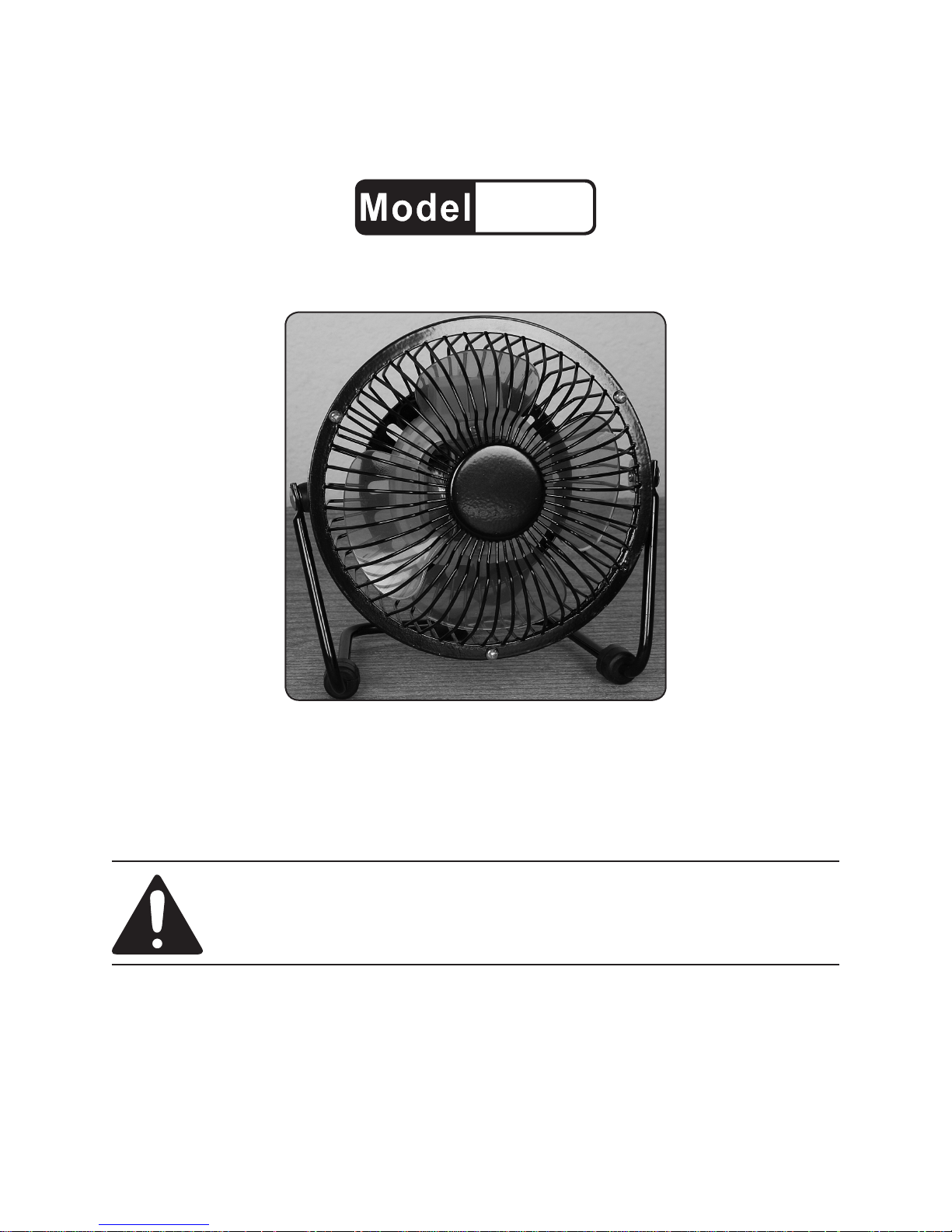
4” MINI FAN
66471
SET UP AND OPERATING INSTRUCTIONS
Distributed exclusively by Harbor Freight Tools®.
3491 Mission Oaks Blvd., Camarillo, CA 93011
Visit our website at: http://www.harborfreight.com
Read this material before using this product.
Failure to do so can result in serious injury.
SAVE THIS MANUAL.
Copyright© 2008 by Harbor Freight Tools®. All rights reserved. No portion of this manual or any artwork
contained herein may be reproduced in any shape or form without the express written consent of
Harbor Freight Tools. Diagrams within this manual may not be drawn proportionally. Due to continuing
improvements, actual product may differ slightly from the product described herein. Tools required for
assembly and service may not be included.
For technical questions or replacement parts, please call 1-800-444-3353.
Page 2
CAUTION
SAVE THESE
Read Rules for Safe Operation and
Instructions Carefully.
WARNING
To reduce risk of re or electric 1.
shock, do not use Fan with any
solid-state speed control device.
This appliance has a polarized 2.
plug (one blade is wider than the
other). To reduce the risk of electric shock, this plug is intended to
t into a polarized outlet only one
way. If the plug does not t fully
in the outlet, reverse the plug. If
it still does not t, contact a qualied electrician. Do not change the
plug in any way. Do not attempt to
defeat this safety feature.
INSTRUCTIONS.
Safety Symbols
In this manual, on the labeling,
and all other information provided with this product:
This is the safety alert
symbol. It is used to alert
you to potential personal
injury hazards. Obey all
safety messages that
follow this symbol to avoid
possible injury or death.
DANGER indicates
a hazardous
situation which, if not
avoided, will result in death or
serious injury.
RULES FOR SAFE
OPERATION
Do not leave Fan running while unat-1.
tended.
Never insert ngers, pencils, or any 2.
other object through Front or Rear
Blade Guards.
Disconnect Fan when relocating it.3.
Disconnect Fan before removing 4.
grilles for cleaning.
Be sure fan is on a stable surface 5.
when operating to avoid overturning.
DO NOT use fan in window. Rain 6.
may create electrical hazard.
Direct Power Cord in a safe manner 7.
to avoid tangling.
WARNING
indicates a
hazardous situation which, if
not avoided, could result in
death or serious injury.
CAUTION, used
with the safety
alert symbol, indicates a
hazardous situation which, if
not avoided, could result in
minor or moderate injury.
NOTICE is used to
address practices
not related to personal injury.
CAUTION, without
the safety alert
symbol, is used to address
practices not related to
personal injury.
SKU 66471 For technical questions, please call 1-800-444-3353. Page 2
Page 3

Additional Safety Instructions
SPECIFICATIONS
Maintain labels and nameplates on 1.
the tool. If unreadable or missing,
contact Harbor Freight Tools for a
replacement.
Do not run Power Cord under car-2.
peting. Do not cover cord with throw
rugs, runners or similar coverings. Ar-
range cord away from trafc area and
where it will not be tripped over.
Use only in dry environments. Do 3.
not use in bathrooms, laundry area,
near sinks or other sources of water.
Do not leave the Mini Fan where it
could be inadvertantly knocked into a
source of water.
This product is not a toy. Keep it out 4.
of reach of children.
WARNING: Handling cord on this 5.
product will expose you to lead,
a chemical known to the State of
California to cause cancer, and birth
defects or other reproductive harm.
Wash hands after handling. (California Health & Safety Code § 25249.5,
et seq.)
Electrical Requirements 120 V~ / 60 Hz / .20 A
FOR HOUSEHOLD USE ONLY
UNPACKING
When unpacking, make sure that the
item is intact and undamaged. If any parts
are missing or broken, please call Harbor
Freight Tools at the number shown on the
cover of this manual as soon as possible.
Save This Manual
Keep this manual for the safety warnings and precautions, assembly, operating, inspection, maintenance and cleaning
procedures. Write the product’s serial
number in the back of the manual near the
assembly diagram (or month and year of
purchase if product has no number). Keep
this manual and the receipt in a safe and
dry place for future reference.
There is no assembly required.
The warnings, precautions, and in-6.
structions discussed in this instruction
manual cannot cover all conditions
and situations that may occur. It must
be understood by operator that common sense and caution are factors
which cannot be built into this product, but must be supplied by operator.
SKU 66471 For technical questions, please call 1-800-444-3353. Page 3
Page 4

OPERATION
Read the ENTIRE RULES FOR
SAFE OPERATION section at
the beginning of this manual
including all text under
subheadings therein before set
up or use of this product.
parts, and any other condition that
may affect its safe operation.
Always wear ANSI-approved safety 2.
goggles when cleaning or performing
maintenance on the Mini Fan.
Clean regularly to prevent dust from 3.
accumulating on Blades (3).
To activate, insert Power Cord (24) 1.
into nearest electrical outlet.
Position Mini Fan in the required lo-2.
cation, making sure the Support Leg
(22) is stable and balanced.
Press the Power Switch (16) to the 3.
ON position. When nished, press
the Power Switch to the OFF position.
INSPECTION AND
MAINTENANCE
TO PREVENT
SERIOUS INJURY
FROM ACCIDENTAL
OPERATION OR ELECTRIC
SHOCK: Before appliance
inspection or maintenance,
make sure the appliance’s
switch is turned off and the
cord is unplugged.
TO PREVENT SERIOUS
INJURY FROM APPLIANCE
FAILURE: Do not use
damaged appliances. If
abnormal noise or vibration
occurs, have the problem
corrected before further use.
To open the Mini Fan, use a narrow 4.
Phillips-head screwdriver (not included) to remove the three Screws(1).
Then remove the Front Cover (2).
Use a damp cloth to clean the 5.
Blades. Dry with another cloth.
Replace Front Cover and use screw-6.
driver to fasten Front Cover back into
place until secure.
No lubrication is required.7.
Record Product’s Serial Number
Here:
Note: If product has no serial number,
record month and year of purchase
instead.
Note: Some parts on the Parts List and
Assembly Diagram (see next page)
are listed and shown for illustration
purposes only, and are not available
individually as replacement parts.
BEFORE EACH USE,1. inspect con-
dition of the Fan. Check for loose
screws, misalignment or binding of
moving parts, cracked or broken
SKU 66471 For technical questions, please call 1-800-444-3353. Page 4
Page 5

PARTS LIST AND ASSEMBLY DIAGRAM
Part Description Qty.
1 Screw (M3 x 6) 3
2 Front Cover 1
3 Blades 4
4 Screw (M3 x 25) 2
5 Spring Washer 2
6 Front Rotor Gasket 1
7 Wool Seal 2
8 Rubber Washer 2
9 Rotor 1
10 Stator 1
11 Bushing 2
12 Clip Ring 2
Part Description Qty.
13 Rear Rotor Gasket 1
14 Rear Cover 2
15 Screw (M4 x 8) 2
16 Power Switch 1
17 Screw (M3 x 3) 2
18 Connector 2
19 Rubber Gasket 2
20 Flat Washer 2
21 Rivet 2
22 Support Leg 1
23 Rubber Foot 3
24 Power Cord 1
THE MANUFACTURER AND/OR DISTRIBUTOR HAS PROVIDED THE PARTS LIST AND ASSEMBLY DIAGRAM
IN THIS MANUAL AS A REFERENCE TOOL ONLY. NEITHER THE MANUFACTURER OR DISTRIBUTOR MAKES
ANY REPRESENTATION OR WARRANTY OF ANY KIND TO THE BUYER THAT HE OR SHE IS QUALIFIED
TO MAKE ANY REPAIRS TO THE PRODUCT, OR THAT HE OR SHE IS QUALIFIED TO REPLACE ANY PARTS
OF THE PRODUCT. IN FACT, THE MANUFACTURER AND/OR DISTRIBUTOR EXPRESSLY STATES THAT
ALL REPAIRS AND PARTS REPLACEMENTS SHOULD BE UNDERTAKEN BY CERTIFIED AND LICENSED
TECHNICIANS, AND NOT BY THE BUYER. THE BUYER ASSUMES ALL RISK AND LIABILITY ARISING OUT OF
HIS OR HER REPAIRS TO THE ORIGINAL PRODUCT OR REPLACEMENT PARTS THERETO, OR ARISING OUT
OF HIS OR HER INSTALLATION OF REPLACEMENT PARTS THERETO.
SKU 66471 For technical questions, please call 1-800-444-3353. Page 5
Please Note: Power Cord (24) Not Shown.
PLEASE READ THE FOLLOWING CAREFULLY
 Loading...