

Page 1
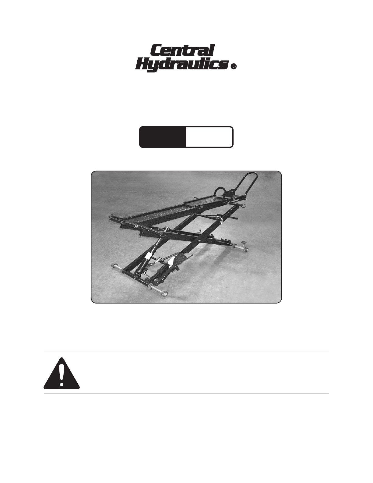
1000 LB. HYDRAULIC
Model
66305
MOTORCYCLE SERVICE LIFT
SET UP AND OPERATING INSTRUCTIONS
Distributed exclusively by Harbor Freight Tools®.
3491 Mission Oaks Blvd., Camarillo, CA 93011
Visit our website at: http://www.harborfreight.com
Read this material before using this product.
Failure to do so can result in serious injury.
SAVE THIS MANUAL.
Copyright© 2008 by Harbor Freight Tools®. All rights reserved. No portion of this manual or any
artwork contained herein may be reproduced in any shape or form without the express written
consent of Harbor Freight Tools. Diagrams within this manual may not be drawn proportionally. Due
to continuing improvements, actual product may differ slightly from the product described herein.
For technical questions or replacement parts, please call 1-800-444-3353.
Page 2
SAVE THIS MANUAL
Keep this manual for the safety warnings and precautions, assembly, operating, inspection, maintenance and cleaning
procedures. Write the product’s serial
number in the back of the manual near the
assembly diagram (or month and year of
purchase if product has no number). Keep
this manual and the receipt in a safe and
dry place for future reference.
NOTICE is used to
address practices
not related to personal injury.
CAUTION, without
the safety alert
symbol, is used to address
practices not related to
personal injury.
IMPORTANT SAFETY
Safety Alert Symbol
and Signal Words
In this manual, on the labeling,
and all other information
provided with this product:
This is the safety alert
symbol. It is used to alert
you to potential personal
injury hazards. Obey all
safety messages that
follow this symbol to avoid
possible injury or death.
DANGER indicates
a hazardous
situation which, if not
avoided, will result in death or
serious injury.
INSTRUCTIONS
INSTRUCTIONS PERTAINING
TO A RISK OF FIRE,
ELECTRIC SHOCK, OR
INJURY TO PERSONS
WARNING – When using tools, basic pre-
cautions should always be followed,
including the following:
General
WARNING - To reduce the risks of electric
shock, re, and injury to persons,
read all the instructions before using
the tool.
Work area
WARNING
indicates a
hazardous situation which, if
not avoided, could result in
death or serious injury.
CAUTION, used
with the safety
alert symbol, indicates a
hazardous situation which, if
not avoided, could result in
minor or moderate injury.
Keep the work area clean and well a.
lighted. Cluttered benches and dark
areas increase the risks of electric
shock, re, and injury to persons.
Do not operate the tool in explo-b.
sive atmospheres, such as in the
presence of ammable liquids,
gases, or dust. The tool is able to
create sparks resulting in the ignition
of the dust or fumes.
Keep bystanders, children, and c.
visitors away while operating the
Page 2SKU 66305 For technical questions, please call 1-800-444-3353.
Page 3

tool. Distractions are able to result in
the loss of control of the tool.
Personal safety
Stay alert. Watch what you are do-a.
ing and use common sense when
operating the tool. Do not use the
tool while tired or under the inuence of drugs, alcohol, or medication. A moment of inattention while
operating the tool increases the risk
of injury to persons.
Dress properly. Do not wear loose b.
clothing or jewelry. Contain long
hair. Keep hair, clothing, and
gloves away from moving parts.
Loose clothes, jewelry, or long hair
increases the risk of injury to persons
as a result of being caught in moving
parts.
Do not overreach. Keep proper c.
footing and balance at all times.
Proper footing and balance enables
better control of the tool in unexpected situations.
d. Use safety equipment. A
dust mask, non-skid safety
shoes and a hard hat must
be used for the applicable
conditions. Wear heavy-duty work
gloves during use.
Risk of Electric Shock. This tool g.
is not provided with an insulated
gripping surface. Contact with a
″live″ wire will also make exposed
metal parts of the tool ″live″ and
shock the operator.
Tool use and care
Use tie downs or another practical a.
way to secure and support the motorcycle on the platform. Holding
the motorcycle by hand or against the
body is unstable and is able to lead to
loss of control.
Do not force the Lift. b. Use the cor-
rect Lift for the application. The cor-
rect tool will do the job better and
safer at the rate for which the tool is
designed.
Do not use the Lift if the controls c.
do not function properly. Any tool
that cannot be controlled is dangerous and must be repaired.
Store the tool when it is idle out of d.
reach of children and other untrained persons. A tool is dangerous
in the hands of untrained users.
Maintain the tool with care. e. A prop-
erly maintained tool reduces the risk
of binding and is easier to control.
e. Always wear eye protec-
tion. Wear ANSI-ap-
proved safety goggles.
f. Always wear hearing
protection when using
the tool. Prolonged expo-
sure to high intensity noise
is liable to cause hearing loss.
Check for misalignment or bind-f.
ing of moving parts, breakage of
parts, and any other condition that
affects the tool’s operation. If dam-
aged, have the tool serviced before
using. Many accidents are caused
by poorly maintained tools. There is a
risk of bursting if the tool is damaged.
Use only accessories that are g.
identied by the manufacturer for
Page 3SKU 66305 For technical questions, please call 1-800-444-3353.
Page 4
the specic tool model. Use of an
accessory not intended for use with
the specic tool model, increases the
risk of injury to persons.
Service
Tool service must be performed a.
only by qualied repair personnel.
When servicing a tool, use only b.
identical replacement parts. Use
only authorized parts.
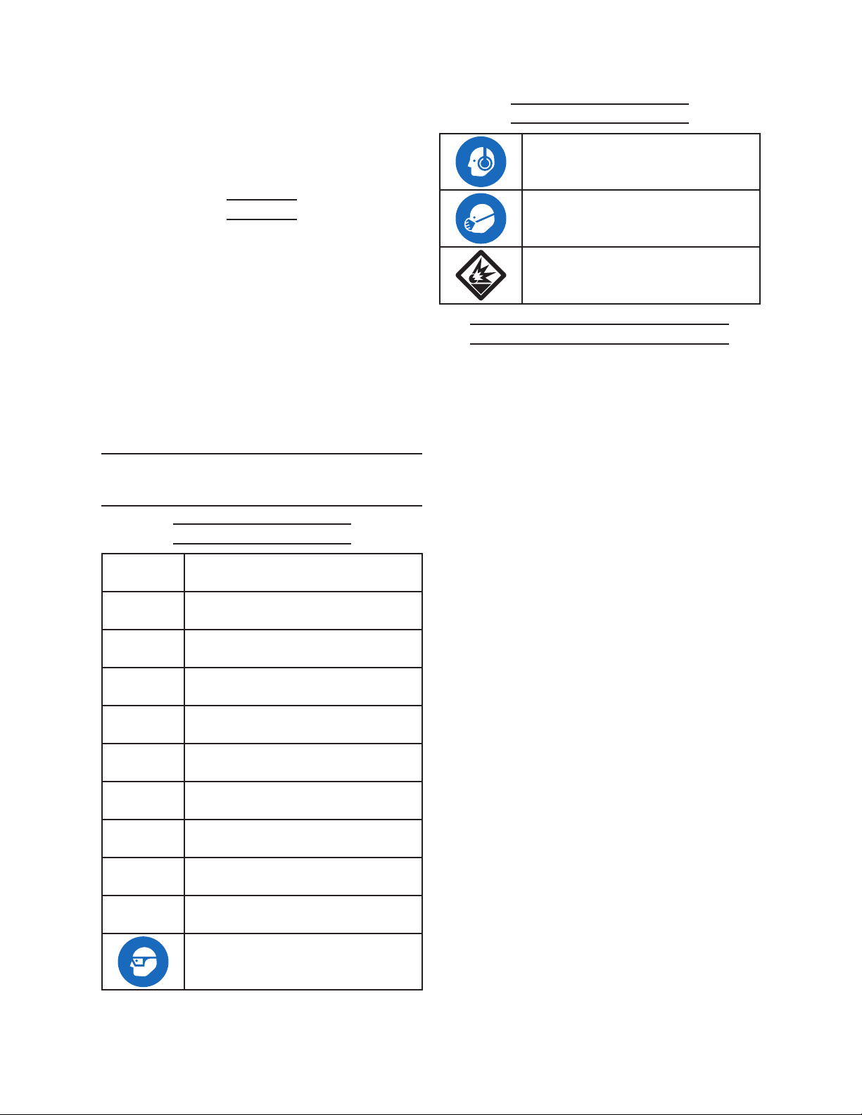
Symbol Denitions
WARNING marking concerning Risk
of Hearing Loss. Wear hearing
protection.
WARNING marking concerning Risk
of Respiratory Injury. Wear NIOSH-
approved dust mask/respirator.
WARNING marking concerning Risk
of Explosion.
Specic Safety Instructions
Use only the lubricants supplied c.
with the tool or specied by the
manufacturer.
SYMBOLS AND SPECIFIC
SAFETY INSTRUCTIONS
Symbol Denitions
Symbol Property or Statement
n
o
.../min
PSI
ft-lb
BPM
CFM
SCFM
NPT
NPS
No-load speed
Revolutions or reciprocation per
minute
Pounds per square inch of pressure
Foot-pounds of torque
Blows per minute
Cubic Feet per Minute ow
Cubic Feet per Minute ow at
standard conditions
National pipe thread, tapered
National pipe thread, straight
Strap Motorcycle to Lift before use.1.
The weight of the motorcycle must be 2.
centered directly over the Deck Plate
(16) during use.
This lift is designed for standard 3.
two-wheel motorcycles only. Do not
attempt to lift a motorcycle with side
car or a three-wheeled vehicle.
Do not exceed the maximum 1000 lb. 4.
weight capacity of this tool. Be aware
of dynamic loading! Dropping or
bouncing load may briey create excess load causing product failure.
Keep all fasteners and pull pins cor-5.
rectly installed and secure when the
Lift is in use.
Always use the Safety Bar (75) as 6.
described in this manual when the
Lift is raised. Never depend on the
Hydraulic Ram (24) alone to keep Lift
elevated.
Do not put Hands, arms, any body 7.
part or object within the interior frame
of the Lift when raising or lowering.
WARNING marking concerning Risk
of Eye Injury. Wear ANSI-approved
eye protection.
Chart continued in next column.
Do not hold onto the Lift as it is raised 8.
or lowered.
Page 4SKU 66305 For technical questions, please call 1-800-444-3353.
Page 5

Do not attempt to manually raise or 9.
lower the Lift. Operate the Lift hydraulically only as described in this
manual only.
Do not leave Lift unattended with a mo-10.
torcycle on it. The Lift is not for long term
storage.
Do not leave any load on the Lift for 11.
an extended period of time. This Lift is
not designed as a storage device. Remove motorcycle from Lift immediately
after completing service operation.
Use only on rm, level unobstructed 12.
surface able to support the weight
of the Lift, the vehicle, and any tools
that will be located in the work area.
Do not use Lift to move the motor-13.
cycle. This Lift is designed to lift the
motorcycle in place only.
Whenever a motorcycle is lifted, the 14.
Safety Bar (75) must be engaged
immediately before any further steps
are taken.
Do not use Lift for any aircraft purpose.15.
For indoor use only.16.
Do not ride on this Lift. Do not ride on 17.
the motorcycle as it is lifted. Riding
on Lift may cause personal injury.
Always control the speed of a loaded 18.
lift. It must raise or lower slowly
when loaded. Never attempt to lower
the Lift when loaded by using the
yellow No Load Pedal (71). The No
Load Pedal is only used to lower the
Lift when it is not loaded.
Do not lower the motorcycle quickly. 19.
Only use the Load Pedal (69) to
slowly lower the Lift when there is a
motorcycle on it. NEVER allow the
vehicle to drop suddenly.
The warnings and precautions dis-20.
cussed in this manual cannot cover
all possible conditions and situations
that may occur. It must be understood by the operator that common
sense and caution are factors which
cannot be built into this product, but
must be supplied by the operator.
Failure to comply with these warn-
ings may result in injury or damage to
property.
SAVE THESE
INSTRUCTIONS.
ASSEMBLY INSTRUCTIONS
The Lift comes completely assembled,
except for the following items: (Refer to
the exploded drawing).
Tie Down Rings: 1. The two front tie
downs are longer than the rear pair.
Slide the front tie downs (13) onto the
rods welded at either side of the front
end of the platform, and secure them
with bolts (14) and nuts (15). Attach
the shorter rear tie-downs (31) to the
rear rods and secure with bolts (14)
and nuts (15).
Wheel Chock: 2. Place the wheel
chock (17) on to the front end of the
platform and align it with a suitable
pair of holes. Slide the long bolt (19)
through a hole in the side of the
platform and through the sleeves
welded to the back of the chock and
out the other side of the platform.
Secure with nut (18).
Front Wheel Attachment. 3. Drop the
ends of the ‘U’ shaped front wheel
Page 5SKU 66305 For technical questions, please call 1-800-444-3353.
Page 6

attachment (21) into the sleeves
welded to the front end of the
platform and secure with a pull pin (7)
and a R-Pin (20) on either side.
Support Leg and Wheel 4.
Assemblies: Identify the two support
leg/wheel assemblies. The front
assembly (74) has a threaded hole
between each pair of wheels. Insert
the front assembly through the
support arm tube at the lower, front
end of the scissor frame. Rotate the
assembly within the tube until the
hole in the centre aligns with the hole
in the tube. Secure with a bolt (26).
Now attach wheels (28), washers (29)
and retaining rings (30) in the order
shown in the diagram below. Identify
the two lock bolts (41) with hand
wheels attached and screw them into
the holes between the wheels on
either side. Insert the rear assembly
(27) through the support arm tube
at the lower, back end of the scissor
frame. Rotate the assembly within the
tube until the hole in the centre aligns
with the hole in the tube. Secure with
a bolt (26). Now attach wheels (28),
washers (29) and retaining rings (30).
How to store the lift vertically.
The lift can be 1.
stored vertically
as shown in
gure below.
WARNING: In
this position the
lift is not free
standing and
must be secured
to a wall with a
heavy duty cable
or chain. Failure
to adequately secure the lift could
result in serious injury or death in
the event the lift tips over.
With the lift in its lowest position 2.
remove the ramp from the end of
the extended platform. Whilst the
platform is still extended remove the
pins from the ‘U’ shaped support on
the end of the extension and fold it
over. Use the two pins to lock it in
this position. Remove the two pins
from the other end of the extension
and push the extension back onto
the main platform until it lines up
with another pair of holes in the rails.
Insert the two pins through the rails to
lock the extension piece in position.
With the help of a second person, 3.
push the rear end of the Motorcycle
Lift against the wall where it will be
secured. Together lift the front end
into a vertical position. As it reaches
the vertical position the weight of the
lift will shift from the wheels to the ‘U’
shaped support leaving the wheels
slightly off the ground. Two people
should continue to support the lift
whilst it is manoeuvred up against the
wall. Whilst one person continues to
support the lift the other will secure
it in position with a heavy cable or
chains and a suitable lock.
Putting the lift back down for 4.
use. When returning the lift to the
horizontal position, equal care is
required to avoid injury to persons.
Reverse the lifting up steps. When
nally lowering the lift to the ground
take hold of the outer part of the
cable tie down bars at the chock
end of the lift to avoid ngers being
trapped under the wheel bars.
Page 6SKU 66305 For technical questions, please call 1-800-444-3353.
Page 7

SPECIFICATIONS
Before Initial Use
Maximum Lifting Capacity 1000 LBS
Maximum Lifting Height 32” Off Floor
Collapsed Height 7-5/8”
Ramp Dimensions 66-3/16” L x 8-3/8” W
Maximum Ramp Extension 84-5/8” Long
Ramp Inside Width 5-3/4”
Wheel Chock Width 5”
Ram Diameter 1.10”
Ram Travel 10-1/4”
Net Weight 165 Lbs.
INITIAL TOOL SET UP/
ASSEMBLY
Read the ENTIRE IMPORTANT
SAFETY INFORMATION
section at the beginning of this
manual including all text under
subheadings therein before set
up or use of this product.
Note: For additional information regarding
the parts listed in the following pages,
refer to the Assembly Diagram near
the end of this manual.
Inspect tool before use, looking
for damaged, loose, and
missing parts or oil leaks. If
any problems are found, do not
use tool until repaired.
Be sure that the Lift is situated on 1.
a solid level surface that can support the combined the weight of this
Lift and any motorcycle that will be
mounted on it.
Purge the Hydraulic Ram.2.
Purging the Hydraulic Ram
Please refer to Hydraulic Ram Assembly Diagram and Parts List near
the end of this manual when performing the following procedure.
Turn the Release Valve (15a) 1/2 turn 1.
counterclockwise. Remove the Oil
Filler Plug (9a).
Pump the Foot Pedal (56) 12 to15 2.
times, until all air is purged from the
pump.
Unpacking
This item is heavy. Ensure that you 1.
have an assistant to help handle and
set up this item.
When unpacking, check to make sure 2.
that the item is intact and undamaged. If any parts are missing or broken, please call Harbor Freight Tools
at the number shown throughout the
manual as soon as possible.
NOTE: This item is pre-assembled at the
factory.
Turn the Release Valve (15a) clock-3.
wise until nger tight.
Top off the hydraulic Ram (24) with 4.
good quality hydraulic oil (not included) until the oil level is even with the
bottom of the Oil Filler Port. Replace
the Oil Filler Plug (9a).
Test the Lift without a load by rais-5.
ing and lowering it. If the lift operates properly you have completed
this process. If the Lift does not raise
or lower smoothly and controllably,
repeat the purging process.
Page 7SKU 66305 For technical questions, please call 1-800-444-3353.
Page 8

IMPORTANT COMPONENTS OF THE LIFT
Front Wheel
Chock (17)
Rear Tie-Down Bracket (31)
Front Wheel Rest (21)
Front
Tie-Down
Bracket (13)
Safety Bar (75)
Safety Bar
Lock Pin (40)
Hydraulic Ram (24)
No Load Pedal (71)
Locking Bolt
Assembly (41)
Load Pedal (69)
Pump Pedal (56)
Figure 1
Load Pedal (69)
Hydraulic Ram (24)
Pump Pedal (56)
yellow
No Load
Pedal (71)
Figure 2
Page 8SKU 66305 For technical questions, please call 1-800-444-3353.
Page 9

OPERATING INSTRUCTIONS
TO PREVENT
SERIOUS INJURY:
Do not adjust or tamper with
any control or component in a
way not specically explained
within this manual. Improper
adjustment can result in tool
failure or other serious
hazards.
Position the Lift in a safe and suitable 1.
area as discussed above.
Rest (21). The Front Wheel Lock will
rotate with the wheel, supporting it
from the rear.
The Wheel Chock (17) can be ad-7.
justed to t your wheel. Remove the
Nut (18) from one end of the Wheel
Lock Axle (19), and slide the Axle out
of the Deck Plate (16). The Wheel
Lock can be moved as needed and
the Wheel Lock Axle inserted in the
appropriate holes in the Deck Plate.
Reinstall the Nut and tighten. See
Figure 3.
Press the Load Pedal (69) to fully 2.
lower the lift.
Pull out the Ramp (1) and Pull Ramp 3.
(8) as needed to accommodate the
length of the motorcycle.
Be sure the Front Wheel Chock (17) 4.
is rotated toward the rear of the Lift.
Roll the motorcycle up the Ramp (1) 5.
and onto the Deck Plate (16).
Front Wheel Rest (21)
Wheel Chock (17)
With a helper holding the motorcycle 8.
upright, secure the motorcycle to the
Lift using the Tie Down Points (13
and 31).
Before lifting any motorcycle, it must 9.
be securely fastened to the Lift using tie-down straps (not supplied) or
other suitable method. Two Front Tie
Down Brackets (13) and two Rear Tie
Down Brackets (31) are built into the
Lift for this purpose.
Refer to the manufacturer’s motorcy-10.
cle service manual for recommended
attachment points on the vehicle.
There must not be hazardous ob-11.
jects (such as utility lines or foreign
objects) nearby that will present a
hazard while working.
Pull Pin (7)
Wheel Lock Axle (19)
Figure 3
Roll the front wheel over the Front 6.
Wheel Chock (17) and into the Wheel
Before lifting the motorcycle, pull out 12.
the Safety Bar Lock Pin (40) to allow
the Safety Bar (75) to rest on the Inner Scissor Arm (35).
To Lift the motorcycle, pump the 13.
Pump Pedal (56) repeatedly until
the motorcycle is lifted to the desired
height.
Page 9SKU 66305 For technical questions, please call 1-800-444-3353.
Page 10

When the motorcycle is lifted, be sure 14.
that the Safety Bar (75) is slightly
above one of the ramps of the Inner
Scissor Arm (35).
Press the Load Pedal (69) until the 15.
Safety Bar (75) is fully engaged with
the ramp of the Inner Scissor Arm
(35). See Figure 4.
Locking Bolt (41)
Inner
Scissor
Arm (35)
insert the Safety Bar Lock Pin (40)
into the hole in the upper axle of the
Safety Bar. This will lock the Safety
Bar in the upright position. See Fig-
ure 5.
Figure 5
Safety Bar Pin (40)
Safety Bar (75)
Figure 4
Once the motorcycle has been lifted, 16.
do not move the Lift around. This Lift
is not designed to transport any load.
The Lift can be immobilized by turning the two Locking Bolts (41) clock-
wise rmly against the oor.
Do not leave the motorcycle on the lift 17.
unattended. If you plan to leave the
area, lower the lift and remove the
motorcycle before leaving.
Do not use the Lift as a storage de-18.
vice.
Pump the Pump Pedal (56) a few 19.
times to remove weight from the
Safety Bar (75).
Press the Load Pedal (69) to GEN-21.
TLY lower the load. NEVER allow the
load to come down quickly or suddenly.
With the load fully lowered, have a 22.
helper hold the motorcycle. Remove
the tie down straps. Roll the motorcycle off the back of the Lift.
Secure the motorcycle.23.
Loosen the two Locking Bolts (41) by 24.
turning a few turns counterclockwise.
Roll the motorcycle lift to a secure 25.
storage area out of the reach of children.
When work has been completed on 26.
the motorcycle, clear all tools away
from the area.
Disengage the Safety Bar (75) from 20.
the ramp of the Inner Scissor Arm
(35). Swing the Safety Bar up and
Page 10SKU 66305 For technical questions, please call 1-800-444-3353.
Page 11

USER-MAINTENANCE
INSTRUCTIONS
Cleaning Maintenance and
Lubrication
Procedures not specically
explained in this manual
must be performed only by a
qualied technician.
TO PREVENT
FROM TOOL FAILURE:
Do not use damaged
equipment. If abnormal noise,
vibration, or leaking air
occurs, have the problem
corrected before further use.
Motorcycle Lift does
not lift
Note: These procedures are in addition to
the regular checks and maintenance
explained as part of the regular operation of the air-operated tool.
Weekly - Pivot Point Lubrication 1.
SERIOUS INJURY
and Safety Inspection:
Lubricate the pivot points of the tool,
using white lithium grease. Inspect for
loose fasteners or any damage to the
Lift. Repair immediately or mark “Out
of Service” until repairs are made.
If the Hydraulic Ram fades or fails to 2.
lift you may need to add oil or purge
the Ram.
Troubleshooting
Possible Causes Likely Solutions
Steel Ball (13a) in the Discharge 1.
Valve or the single-way valve of
the Hydraulic Cylinder does not
seat or seal well.
Steel Ball (13a) in the Single-way 2.
valve does not seat or seal well.
Hydraulic Ram may require 3.
purging.
Discharge Valve is open.4.
Clean or replace these components. 1.
Clean or replace these components. 2.
Purge Ram. See instructions on page 6.3.
Tighten the discharge valve. 4.
Motorcycle Lift
does not lower
Motorcycle Lift
Fades (slowly
lowers on its own)
Oil leaks from top
rod of Hydraulic
Ram (24).
Oil leaks from the
pump and cylinder
Follow all safety precautions whenever diagnosing or servicing the tool.
Discharge Valve is not open1. Check function of Release Linkage Assembly 1.
Leaking Valves or Seals.1.
Low on oil in system. 2.
Hydraulic Cylinder may require 3.
purging.
Ram O-ring (2a or 6a) is worn 1.
out.
O-ring at pump (18a) or Oil Seal 1.
(3a or 10a) is worn out.
(54).
Take to qualied repair technician for service1.
Check oil level. Rell and purge as necessary. 2.
Follow instructions for purging system.
Purge Hydraulic Ram. See instructions on page 6. 3.
Replace the O-ring.1.
Replace the O-ring or Oil Seal.1.
Page 11SKU 66305 For technical questions, please call 1-800-444-3353.
Page 12

OVERALL ASSEMBLY DIAGRAM
75
Page 12SKU 66305 For technical questions, please call 1-800-444-3353.
Page 13

PARTS LIST FOR OVERALL ASSEMBLY
Item # Description QTY
1 Ramp 1
2 Pull Ramp Stand 1
3 End Cap 4
4 Pump Spring 1
5 Nut 2
6 Bolt 2
7 Pull Pin 6
8 Pull Ramp 1
9 Screw 2
10 Nut 2
11 Pull Ramp Guide 2
12 Rivet 2
13 Front Tie-Down Point 2
14 Bolt 4
15 Nut 4
16 Deck Plate 1
17 Wheel Chock 1
18 Nut 2
19 Wheel Lock Axle 1
20 R-Pin 2
21 Front Wheel Rest 1
22 Retaining Ring 4
23 Pump Base Pin 1
24 Hydraulic Ram 1
25 Pump Rod Pin 1
26 Bolt 1
27 Leg 1
28 Wheel 8
29 Washer 12
30 Retaining Ring 12
31 Rear Tie-Down Point 2
32 Retaining Ring 4
33 Pin 1
34 Rubber Gasket 4
35 Inner Scissor Arm 1
36 Retaining Ring 4
37 Pin 2
38 Outer Scissor Arm 1
Item # Description QTY
39 Pin 2
40 Safety Bar Lock Pin 1
41 Locking Bolt Assembly 2
42 Washer 1
43 Screw 1
44 Lever Linkage Assembly 1
45 Nut 1
46 Connecting Rod 1
47 Pin 1
48 Cotter Pin 3
49 Washer 2
50 Connecting Pin 1
51 Washer 2
52 Bushing 1
53 Screw 2
54 Release Linkage Assembly 1
55 Screw 1
56 Pump Pedal 1
57 Retaining Ring 1
58 Pump Link Plate 1
59 Pin 2
60 Pin 2
61 Spring Link Plate 1
62 Bolt 3
63 Nut 1
64 Release Link Ring 1
65 Release Link Plate 1
66 Release Spring 1
67 Nut 1
68 Bolt 1
69 Load Pedal 1
70 Retaining Ring 1
71 No Load Pedal 1
72 Screw 1
73 Nut 1
74 Leg 1
75 Safety Bar 1
Page 13SKU 66305 For technical questions, please call 1-800-444-3353.
Page 14

ASSEMBLY DIAGRAM FOR HYDRAULIC RAM
Note: All parts for the Hydraulic Ram Assembly have an “a” sufx, such as “19a”. Do
not confuse these part numbers with the part numbers for the Overall Assembly
which are listed on page 13, and have no sufx.
Page 14SKU 66305 For technical questions, please call 1-800-444-3353.
Page 15

PARTS LIST FOR HYDRAULIC RAM
Part Description QTY
1a Ram Cap 1
2a Ram O-Ring 1
3a Top Sealing Gasket 1
4a Ram Assembly 1
5a Ram Gasket 1
6a O-Ring 1
7a Cylinder 1
8a Oil Reservoir 1
9a Oil Filler Plug 1
10a Lower Sealing Gasket 1
11a Washer 1
12a Base 1
Part Description QTY
14a Seal 1
15a Release Valve 1
16a Washer 1
17a Pump Cylinder 1
18a O-Ring 1
19a Seal 1
20a Piston Rod 1
21a Pin 3
22a Split Cotter Pin 3
23a Handle Socket 1
24a Link 1
25a Pin 1
13a Steel Ball 3
Note: This parts list is for the Hydraulic Ram Assembly. Please refer to Assembly dia-
gram on previous page (14). All parts for Hydraulic Ram have an “a” sufx. For
example
PLEASE READ THE FOLLOWING CAREFULLY
THE MANUFACTURER AND/OR DISTRIBUTOR HAS PROVIDED THE PARTS LIST AND ASSEMBLY
DIAGRAM IN THIS DOCUMENT AS A REFERENCE TOOL ONLY. NEITHER THE MANUFACTURER
OR DISTRIBUTOR MAKES ANY REPRESENTATION OR WARRANTY OF ANY KIND TO THE BUYER
THAT HE OR SHE IS QUALIFIED TO MAKE ANY REPAIRS TO THE PRODUCT, OR THAT HE OR SHE
IS QUALIFIED TO REPLACE ANY PARTS OF THE PRODUCT. IN FACT, THE MANUFACTURER AND/
OR DISTRIBUTOR EXPRESSLY STATES THAT ALL REPAIRS AND PARTS REPLACEMENTS SHOULD
BE UNDERTAKEN BY CERTIFIED AND LICENSED TECHNICIANS, AND NOT BY THE BUYER. THE
BUYER ASSUMES ALL RISK AND LIABILITY ARISING OUT OF HIS OR HER REPAIRS TO THE
ORIGINAL PRODUCT OR REPLACEMENT PARTS THERETO, OR ARISING OUT OF HIS OR HER
INSTALLATION OF REPLACEMENT PARTS THERETO.
Page 15SKU 66305 For technical questions, please call 1-800-444-3353.
Page 16

LIMITED 90 DAY WARRANTY
Harbor Freight Tools Co. makes every effort to assure that its products meet high
quality and durability standards, and warrants to the original purchaser that this product is free from defects in materials and workmanship for the period of 90 days from
the date of purchase. This warranty does not apply to damage due directly or indirectly,
to misuse, abuse, negligence or accidents, repairs or alterations outside our facilities,
criminal activity, improper installation, normal wear and tear, or to lack of maintenance.
We shall in no event be liable for death, injuries to persons or property, or for incidental,
contingent, special or consequential damages arising from the use of our product. Some
states do not allow the exclusion or limitation of incidental or consequential damages, so
the above limitation of exclusion may not apply to you. THIS WARRANTY IS EXPRESSLY IN LIEU OF ALL OTHER WARRANTIES, EXPRESS OR IMPLIED, INCLUDING THE
WARRANTIES OF MERCHANTABILITY AND FITNESS.
To take advantage of this warranty, the product or part must be returned to us with
transportation charges prepaid. Proof of purchase date and an explanation of the complaint must accompany the merchandise. If our inspection veries the defect, we will either repair or replace the product at our election or we may elect to refund the purchase
price if we cannot readily and quickly provide you with a replacement. We will return repaired products at our expense, but if we determine there is no defect, or that the defect
resulted from causes not within the scope of our warranty, then you must bear the cost
of returning the product.
This warranty gives you specic legal rights and you may also have other rights
which vary from state to state.
3491 Mission Oaks Blvd. • PO Box 6009 • Camarillo, CA 93011 • (800) 444-3353
Record Product’s Serial Number Here:
Note: If product has no serial number, record month and year of purchase instead.
Note: Some parts are listed and shown for illustration purposes only, and are not avail-
able individually as replacement parts.
Page 16SKU 66305 For technical questions, please call 1-800-444-3353.
 Loading...