

Page 1
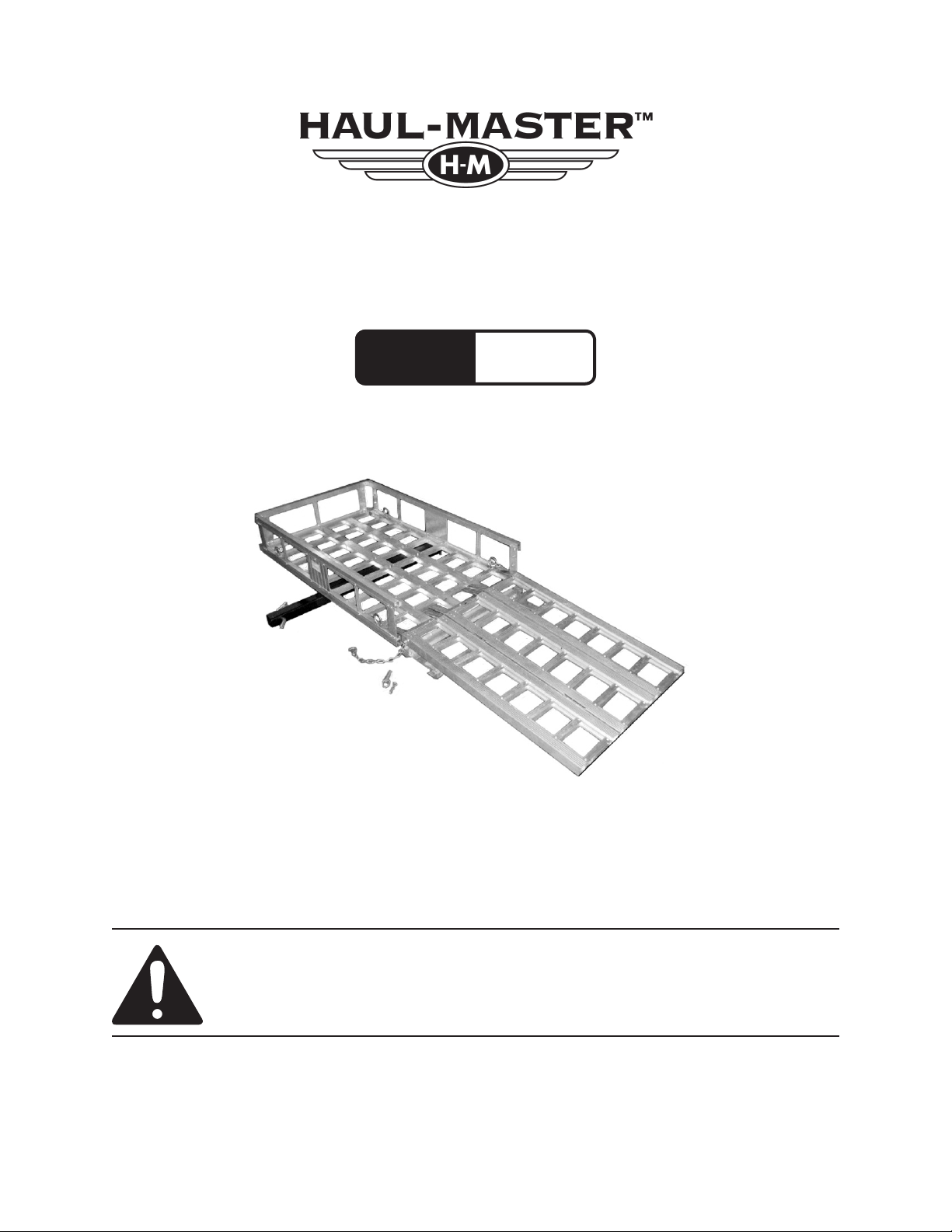
ALUMINUM MOBILITY
Model
66303
DEVICE CARRIER
SET UP AND OPERATING INSTRUCTIONS
Diagrams within this manual may not be drawn proportionally.
Due to continuing improvements, actual product may differ slightly from the product described herein.
Distributed exclusively by Harbor Freight Tools®.
3491 Mission Oaks Blvd., Camarillo, CA 93011
Visit our website at: http://www.harborfreight.com
Read this material before using this product.
Failure to do so can result in serious injury.
SAVE THIS MANUAL.
Copyright© 2008 by Harbor Freight Tools®. All rights reserved. No portion of this
manual or any artwork contained herein may be reproduced in any shape or form
without the express written consent of Harbor Freight Tools.
For technical questions or replacement parts, please call 1-800-444-3353.
Rev 09g
Page 2

SAVE THIS MANUAL
Keep this manual for the safety warnings and precautions, assembly, operating,
inspection, maintenance and cleaning procedures. Write the product’s serial number
in the back of the manual (or month and
year of purchase if product has no number). Keep this manual and the receipt in
a safe and dry place for future reference.
NOTICE is used to
address practices
not related to personal injury.
CAUTION, without
the safety alert
symbol, is used to address
practices not related to
personal injury.
General Safety Rules
IMPORTANT SAFETY
INFORMATION
In this manual, on the labeling,
and all other information
provided with this product:
This is the safety alert
symbol. It is used to alert
you to potential personal
injury hazards. Obey all
safety messages that
follow this symbol to avoid
possible injury or death.
DANGER indicates
a hazardous
situation which, if not
avoided, will result in death or
serious injury.
WARNING
indicates a
hazardous situation which, if
not avoided, could result in
death or serious injury.
CAUTION, used
with the safety
alert symbol, indicates a
hazardous situation which, if
not avoided, could result in
minor or moderate injury.
WARNING! Read all instructions
Failure to follow all instructions
listed below may result in
serious injury.
SAVE THESE INSTRUCTIONS
Area safety1.
Make sure the area in which the Car-a.
rier is assembled is clean and well
lit. Cluttered or dark areas invite
accidents.
Keep children and bystanders away b.
while using the Carrier. Distractions
can cause you to lose control.
Personal safety3.
Stay alert, watch what you are doing a.
and use common sense when using
the Carrier. Do not use the Carrier
while you are tired or under the inuence of drugs, alcohol or medication.
A moment of inattention while using the Carrier may result in serious
personal injury.
Use safety equipment. Wear ANSI-b.
approved safety impact eye goggles
and heavy duty work gloves when
setting up or taking down the Carrier
to avoid eye injury and/or injury from
sharp edges. Safety equipment
such as non-skid safety shoes will
reduce personal injuries.
Page 2SKU 66303 For technical questions, please call 1-800-444-3353.
Page 3

Do not overreach. Keep proper foot-c.
ing and balance at all times. This
enables better control of the Carrier
in unexpected situations.
ensure that the safety of the Carrier
is maintained.
Specic Safety Rules
Dress properly. Do not wear loose d.
clothing or jewelry. Keep your hair,
clothing and gloves away from moving parts. Loose clothes, jewelry or
long hair can be caught in moving
parts.
Carrier use and care4.
Use the correct Carrier for your ap-a.
plication. The correct Carrier will do
the job better and safer at the rate
for which it was designed.
Store the Carrier out of reach of b.
children and do not allow people
unfamiliar with the Carrier or these
instructions to use the Carrier. Use
of carrier by untrained people may
not be safe.
Maintain the Carrier. Check for c.
misalignment or binding of moving
parts, breakage of parts and any
other condition that may affect the
Carrier’s operation. If damaged,
have the Carrier repaired before
use. Many accidents are caused by
poorly maintained equipment.
This Carrier has a maximum weight 1.
capacity of 500 pounds. Do not
exceed the 500 pound capacity. Be
aware of dynamic loading! Sudden
load movement may briey create
excess load causing product failure.
Do not exceed 55 MPH while the 2.
Carrier is attached.
Always secure the Carrier as close 3.
to your vehicle as possible, minimizing the distance of the Carrier and its
load from your vehicle.
Center load on Carrier.4.
Inspect before use; do not use if parts 5.
are damaged or broken. Check all
bolts and nuts in the Carrier. Do not
use if damaged.
Turn off the vehicle’s ignition and set 6.
the parking brake before loading an
object onto the Carrier or unloading.
Do not ride on vehicle being loaded 7.
or unloaded onto Carrier during use.
Use this Carrier in accordance with d.
these instructions and in the manner intended for this particular type
of product, taking into account the
area conditions and the task to
be performed. Use of this Carrier
for operations different from those
intended could result in a hazardous
situation.
Service5.
Have this Carrier serviced by a a.
qualied repair person using only
identical replacement parts. This will
Make sure to read and understand all 8.
instructions and warnings set forth by
the manufacturer of the vehicle that
the carrier will be used with.
Prior to transporting a load make sure 9.
the Ramps (4) of the Carrier are secured within the Carrier using ropes,
tie-downs, etc. Also make sure the
Hinged Top Brace (3) is in its upright
position and locked in place with the
Lock Pin (5) and R-Pin (13).
The ends of the Carrier’s Ramps (4) 10.
must rest at on a solid, level, and at
Page 3SKU 66303 For technical questions, please call 1-800-444-3353.
Page 4

surface when loading and unloading
an object.
This product is not a toy. Keep it out 11.
of reach of children.
Never ride a motorized object (pow-12.
ered scooters, lawn tractors, ATV’s,
etc.) onto or off the Carrier. Only
load/unload with the motorized object
empty of cargo and people.
Follow D.O.T. (Department of Trans-13.
portation) guidelines for installation
and use.
Make sure to secure the load on the 14.
Carrier with ropes, and/or tie-downs
before transporting. Check that the
tongue portion of ramp ts onto Carrier platform.
PRODUCT SPECIFICATIONS
Maximum
Weight Capacity
Construction
Vehicle Hitch
Receiver Size
500 Pounds
Extruded aluminum carrier
and ramps. Formed steel
hitch and hitch plate.
Carbon steel hardware.
Thermoplastic end caps.
2” (Vehicle hitch requires
a Class III or Class IV tow
rating.)
UNPACKING
When unpacking, make sure that the
item is intact and undamaged. If any parts
are missing or broken, please call Harbor
Freight Tools at the number shown on the
cover of this manual as soon as possible.
Only use the Carrier with a properly 15.
installed Class III or Class IV 2 inch
hitch receiver capable of supporting
the Carrier and its load.
Maintain labels and nameplates on 16.
the Carrier. These carry important
safety information. If unreadable or
missing, contact Harbor Freight Tools
for a replacement
The warnings, precautions, and in-17.
structions discussed in this instruction
manual cannot cover all possible conditions and situations that may occur.
It must be understood by the operator
that common sense and caution are
factors which cannot be built into this
product, but must be supplied by the
operator.
SAVE THESE
INSTRUCTIONS.
ASSEMBLY INSTRUCTIONS
Read the ENTIRE IMPORTANT
SAFETY INFORMATION section
at the beginning of this manual
including all text under
subheadings therein before
assembly of this product.
Set all parts on a at, level surface 1.
large enough for assembly.
Fasten Supports (6,7,8 & 9) to Body 2.
(1) using Bolts (14) and Nuts (15).
See Figure 1, below.
7
8
6
8
9
Figure 1
7
8
8
6
Page 4SKU 66303 For technical questions, please call 1-800-444-3353.
Page 5

Use the Bolts and Nuts to connect 3.
the U-shaped Top Brace (2) to the top
of the various Supports (6-9). See
Figure 2, below.
2
Figure 2
9
8
Place the Hinged Top Brace (3) onto 4.
the Supports along the ramp side.
Then align the holes on both Braces
(2,3) and insert Lock Pins. Secure
the Lock Pins (5) in place using the
R-Pins (13). See Figure 3, below.
Figure 3
13
Use the Bolts and Nuts to fasten the 5.
Hinged Top Brace (3) to the Supports.
See Figure 4, below.
Figure 4
3
Use wrench and screwdriver (not 6.
included) to tighten all Bolts and Nuts
until fastened securely.
Use Bolts (16), Washers (17) and 7.
Nuts (18) to attach the Hitch (10) to
the underside of the Body. Please
note that the Hitch extension should
be opposite the side with the reec-
tors. See Figure 5, below.
Figure 5
7
1
10
16, 17 & 18
5
Attach the Tie-Down Hooks (21) to 8.
the Body and fasten them securely
using the Washers (22) and Nuts
(23). See Figure 6, below.
Figure 6
21
Page 5SKU 66303 For technical questions, please call 1-800-444-3353.
Page 6

Remove the Pin (11) and Lock Pin 9.
(12) from the Hitch.
With assistance, lift Carrier and insert 10.
Hitch (10) into vehicle’s receiver
hitch. Align hole in Carrier’s Hitch
with hole in vehicle’s receiver hitch.
Insert Pin (11) through holes in both
hitches, and secure Pin using Lock
Pin. See Figure 7.
WARNING! 2. All persons not involved
in loading or unloading the Carrier
must stand clear of the unit.
Remove the two R-Pins (13) and 3.
Lock Pins from the Hinged Top Brace.
Then completely lower the Hinged
Top Brace. See Figures 8 and 9,
below.
12
2” VEHICLE HITCH RECEIVER
(NOT INCLUDED)
10
Figure 7
11
5
3
5
Figure 8
13
5
OPERATING INSTRUCTIONS
Read the ENTIRE IMPORTANT
SAFETY INFORMATION section
at the beginning of this manual
including all text under
subheadings therein before use
of this product.
WARNING!1. Do not exceed this
Carrier’s maximum weight capacity of
500 pounds.
3
5
13
Figure 9
Set the three Ramps (4) side by side 4.
with their Front edge protruding onto
the edge of the Carrier’s Body (1).
IMPORTANT: Make sure the one
Ramp without the Chain is positioned
Page 6SKU 66303 For technical questions, please call 1-800-444-3353.
Page 7

between the two Ramps with Chains.
See Figure 10, below.
The ends of the Carrier’s Ramps (4) 5.
must rest at on a solid, level, and
at surface when loading and unload-
ing an object. See Figure 10, below.
Figure 10
With assistance, push the load up the 7.
Ramp (4) and onto the Carrier. Make
sure the load is equally centered on
the Carrier. Then secure the load in
place using appropriate tie-downs,
ropes, etc. (not included).
Once the load is secured, remove the 8.
Chain from the two outer Ramps (4).
Place all three Ramps in the Carrier
and secure with tie-downs, ropes, etc.
See 12, below.
4
4
Make sure to securely attach the 6.
Chain on each side of the two outer
Ramps (4) to the rings on the Small
Supports (8) located on each side of
the Body. See Figure 11, below.
4
Figure 11
CHAI N
Figure 12
Raise the Hinged Top Brace (3) all the 9.
way. Then insert the two Lock Pins
(5) and R-Pins (13) to secure it in
position.
The Carrier is now ready to transport 10.
a load.
Page 7SKU 66303 For technical questions, please call 1-800-444-3353.
Page 8

MAINTENANCE AND
SERVICING
Inspection, Maintenance, and
Cleaning
Procedures not specically
explained in this manual
must be performed only by a
qualied technician.
TO PREVENT
SERIOUS INJURY
FROM ACCIDENTAL
OPERATION:
Remove any load from the
unit before performing any
inspection, maintenance, or
cleaning procedures.
TO PREVENT SERIOUS
INJURY FROM EQUIPMENT
FAILURE:
Do not use damaged
equipment. If abnormal noise
or vibration occurs, have the
problem corrected before
further use.
BEFORE EACH USE,1. inspect the
general condition of the Carrier.
Check misalignment, loose or damaged parts and any other condition
that may affect its safe operation.
BEFORE EACH USE, 2. make sure
any dirt, debris, oil, grease, etc. are
cleaned off the Carrier. Clean the
Carrier with a clean, moist cloth. Do
not use solvents.
PERIODICALLY, 3. check all hardware
for tightness.
Record Product’s Serial Number Here:
Note: If product has no serial number, record month and year of purchase instead.
Note: Some parts are listed and shown for illustration purposes only, and are not avail-
able individually as replacement parts.
PLEASE READ THE FOLLOWING CAREFULLY
THE MANUFACTURER AND/OR DISTRIBUTOR HAS PROVIDED THE PARTS LIST AND ASSEMBLY DIAGRAM
IN THIS MANUAL AS A REFERENCE TOOL ONLY. NEITHER THE MANUFACTURER OR DISTRIBUTOR MAKES
ANY REPRESENTATION OR WARRANTY OF ANY KIND TO THE BUYER THAT HE OR SHE IS QUALIFIED
TO MAKE ANY REPAIRS TO THE PRODUCT, OR THAT HE OR SHE IS QUALIFIED TO REPLACE ANY PARTS
OF THE PRODUCT. IN FACT, THE MANUFACTURER AND/OR DISTRIBUTOR EXPRESSLY STATES THAT
ALL REPAIRS AND PARTS REPLACEMENTS SHOULD BE UNDERTAKEN BY CERTIFIED AND LICENSED
TECHNICIANS, AND NOT BY THE BUYER. THE BUYER ASSUMES ALL RISK AND LIABILITY ARISING OUT OF
HIS OR HER REPAIRS TO THE ORIGINAL PRODUCT OR REPLACEMENT PARTS THERETO, OR ARISING OUT
OF HIS OR HER INSTALLATION OF REPLACEMENT PARTS THERETO.
Page 8SKU 66303 For technical questions, please call 1-800-444-3353.
Page 9

PARTS LIST & ASSEMBLY DIAGRAM
Part # Description Qty. Part # Description Qty.
1 Body 1 13 R-Pin 2
2 Top Brace 1 14 Cup Head Bolt (M5 x 12) 60
3 Hinged Top Brace 1 15 Hex Nut (M5) 60
4 Ramp 3 16 Cup Head Bolt (M6 x 45) 10
5 Lock Pin 2 17 Washer (#6) 20
6 Middle Support 6 18 Hex Nut (M6) 10
7 Support With Reector 2 19 Hex Bolt (M8 x 30) 2
8 Small Support 6 20 Hex Nut (M8) 2
9 Large Support 2 21 Tie Down Hook 4
10 Hitch 1 22 Washer 4
11 Pin 1 23 Nut 4
12 Lock Pin 1
7
16, 17, 18
9
5
13
21, 22, 23
4
8
6
14, 15
19, 20
3
10
2
1
11, 12
Page 9SKU 66303 For technical questions, please call 1-800-444-3353.
Page 10

LIMITED 90 DAY WARRANTY
Harbor Freight Tools Co. makes every effort to assure that its products meet high
quality and durability standards, and warrants to the original purchaser that this product is free from defects in materials and workmanship for the period of 90 days from
the date of purchase. This warranty does not apply to damage due directly or indirectly,
to misuse, abuse, negligence or accidents, repairs or alterations outside our facilities,
criminal activity, improper installation, normal wear and tear, or to lack of maintenance.
We shall in no event be liable for death, injuries to persons or property, or for incidental,
contingent, special or consequential damages arising from the use of our product. Some
states do not allow the exclusion or limitation of incidental or consequential damages, so
the above limitation of exclusion may not apply to you. THIS WARRANTY IS EXPRESSLY IN LIEU OF ALL OTHER WARRANTIES, EXPRESS OR IMPLIED, INCLUDING THE
WARRANTIES OF MERCHANTABILITY AND FITNESS.
To take advantage of this warranty, the product or part must be returned to us with
transportation charges prepaid. Proof of purchase date and an explanation of the complaint must accompany the merchandise. If our inspection veries the defect, we will either repair or replace the product at our election or we may elect to refund the purchase
price if we cannot readily and quickly provide you with a replacement. We will return repaired products at our expense, but if we determine there is no defect, or that the defect
resulted from causes not within the scope of our warranty, then you must bear the cost
of returning the product.
This warranty gives you specic legal rights and you may also have other rights
which vary from state to state.
3491 Mission Oaks Blvd. • PO Box 6009 • Camarillo, CA 93011 • (800) 444-3353
Page 10SKU 66303 For technical questions, please call 1-800-444-3353.
 Loading...