

Page 1
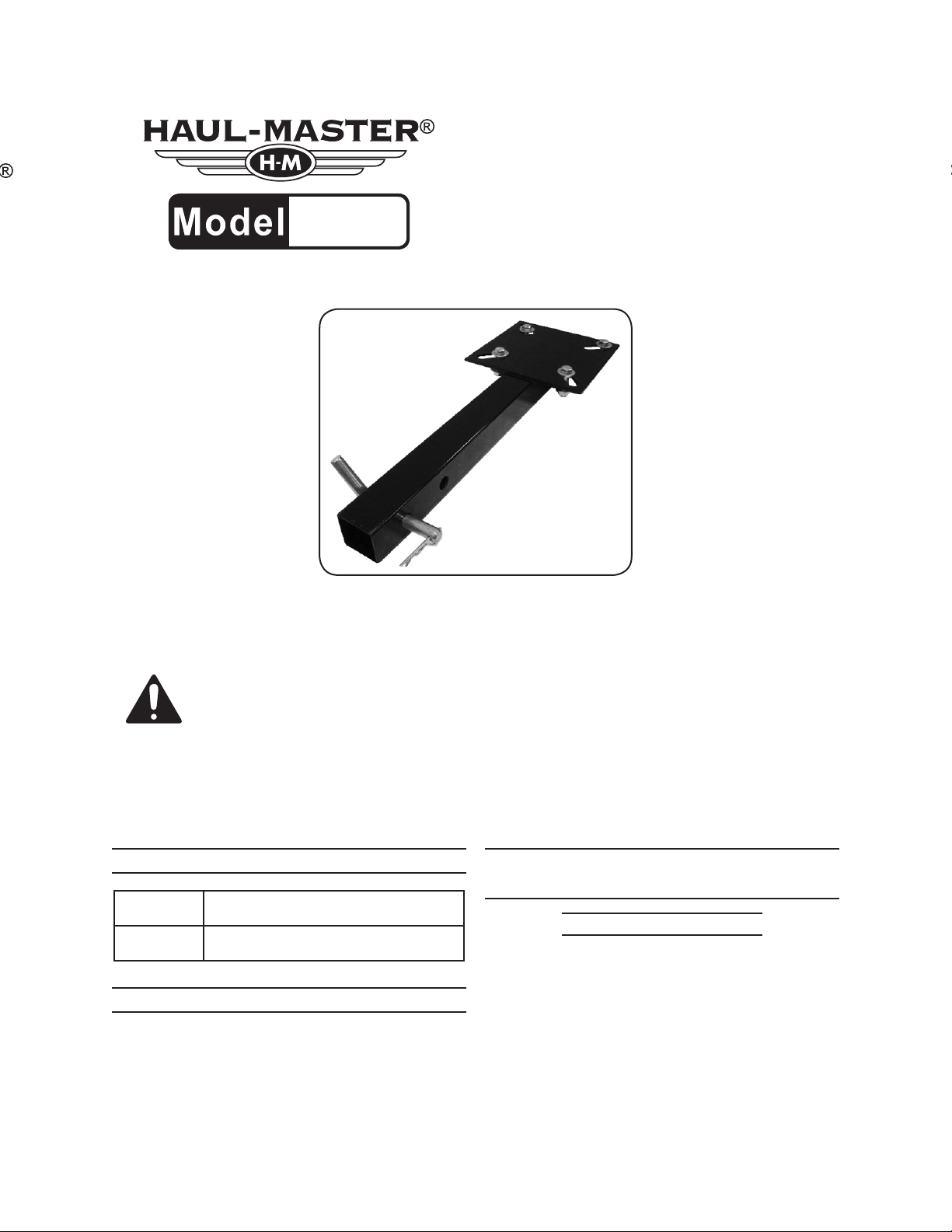
HITCH MOUNT
66260
VISE PLATE
INSTRUCTIONS AND PRECAUTIONS
Distributed exclusively by Harbor Freight Tools®.
3491 Mission Oaks Blvd., Camarillo, CA 93011
Visit our website at: http://www.harborfreight.com
SAVE THESE INSTRUCTIONS. READ ALL
PRECAUTIONS AND INSTRUCTIONS.
Copyright© 2008 by Harbor Freight Tools®. All rights reserved. No portion of this document or any artwork contained
herein may be reproduced in any shape or form without the express written consent of Harbor Freight Tools.
Diagrams within this document may not be drawn proportionally. Due to continuing improvements, actual product
may differ slightly from the product described herein. Tools required for assembly and servise may not be included.
For technical questions or replacement parts, please call 1-800-444-3353.
SPECIFICATIONS
Material
Vise Mounting
Holes
Square Steel Tube - 22"L x 2"
Vise Mount Plate - 7-7/8"L x 7-7/8W x 3/16"T
1-7/8"L x 5/8"W (4)
UNPACKING
When unpacking, make sure that the item
is intact and undamaged. If any parts are missing
or broken, please call Harbor Freight Tools at the
number shown on the cover of this document as
soon as possible.
IMPORTANT SAFETY
INFORMATION
Assembly Precautions
Assemble only according to these instruc-1.
tions. Improper assembly can create hazards.
Fits any standard 2" hitch receiver. 2.
Wear ANSI-approved safety goggles and 3.
heavy-duty work gloves during assembly and
set-up.
Keep assembly area clean and well lit.4.
Page 2
Keep bystanders out of the area during as-5.
sembly.
Do not assemble when tired or when under 6.
the inuence of drugs or medication.
Use Precautions
This product is NOT designed to pull, tow 1.
or push.
This product is not a toy. Do not allow 2.
children to play with or near this item.
Use as intended only.3.
Inspect before every use; do not use if 4.
parts are loose or damaged.
Maintain product labels and nameplates. 5.
These carry important safety information.
If unreadable or missing, contact Harbor
Freight Tools for a replacement.
ASSEMBLY INSTRUCTIONS
Read the ENTIRE IMPORTANT
SAFETY INFORMATION section at the
beginning of this document including
all text under subheadings therein
before set up or use of this product.
Assembly
The only assembly necessary is mounting 1.
the Hitch Mount Vise Plate onto the vehicle’s
standard 2" receiver.
OPERATION
Wear ANSI-approved safety goggles and 1.
heavy-duty work gloves during assembly and
use.
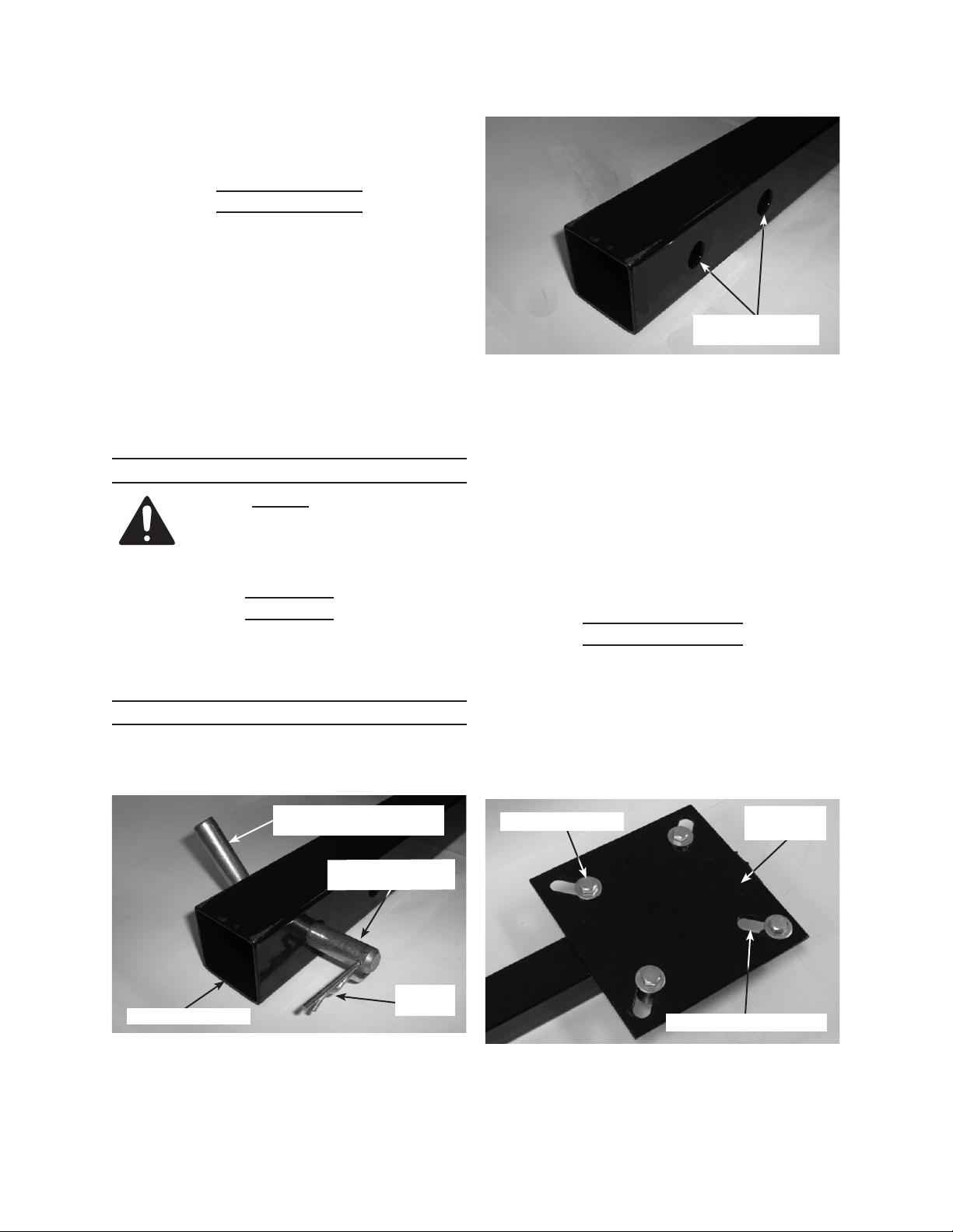
Receiver Retaining
Pin Holes
Fig. 2
3. Slide the Receiver Tube (1) into the vehicle’s
receiver with the at side of the Vise Mount
Plate facing up. (See Fig. 3.)
Align the holes in the Receiver Tube with 4.
those in the vehicle’s receiver. Insert the
Receiver Retaining Pin through the holes in
both the Receiver Tube and vehicle’s receiver, and out the other side.
Replace the Hairpin Clip. a.
Vise can be mounted before or after this b.
step.
Mounting the Vise
Remove the four bolts from the Vise Mount-1.
ing Plate (3), unless the vise is already
mounted. (See Fig. 3.)
Put the 6" vise, or any size vise with mount-2.
ing holes that align properly with the Vise
Mounting Holes (4), on top of the Vise Mount
Plate (3) in the desired orientation.
Angled End of
Receiver Retaining Pin (5)
Receiver Retaining
Pin (5)
Hairpin
Receiver Tube (1)
Fig. 1
2. Pull out the Hairpin Clip (2) and slide out the
Receiver Retaining Pin (5).
Clip (2)
Mounting Bolts (6)
Vise Mounting Holes (4)
Fig. 3
3. Align up the holes in the vise with those in
the Vise Mounting Plate. (See Fig. 3.)
Vise Mount
Plate (3)
SKU 66260 For technical questions, please call 1-800-444-3353. Page 2
Page 3

Secure the vise to the Vise Mount Plate (3). 4.
Slide a Flat Washer (7) onto a Mounting Bolt a.
(6)
Drop the Bolt/Washer assembly down b.
through the hole in the vise and through the
Vise Mounting Hole (4).
From below the Vice Mount Plate (3), slide c.
on another Flat Washer (7) and screw a
Lock Nut (8) onto the bolt.
Repeat for the three remaining Mounting d.
Bolts.(6)
With 17mm wrenches or other appropriate 5.
tools, tighten the Mounting Bolts (6) and Lock
Nuts (8) securely.
Unless the Vise is needed elsewhere for 6.
other tasks, it can be left mounted on the
Hitch Mount Vise Plate, but remove the Vise
Plate/Vise from the vehicle before driving.
After use, brush off and wipe down the Vise 7.
Plate.
To remove the Hitch Mount Vise Plate from 8.
the vehicle’s receiver.
Pull out the Hairpin Clip (2) that locks the a.
Receiver Retaining Pin (5) in position.
Slide the Receiver Retaining Pin back out. b.
Slide the Hitch Mount Vise Plate out of, and 9.
away from the vehicle’s receiver.
Reinstall the Receiver Retaining Pin and 10.
slide the Hairpin Clip back so they do not
become lost.
Store this Vise in a clean, dry location away 11.
from children.
MAINTENANCE/REPAIR
If the Receiver Tube (1) or Vise Mount Plate 2.
becomes damaged, it should be repaired by
a qualied technician.
PLEASE READ THE FOLLOWING
CAREFULLY
THE MANUFACTURER AND/OR DISTRIBUTOR HAS
PROVIDED THE PARTS LIST AND ASSEMBLY DIAGRAM
IN THIS DOCUMENT AS A REFERENCE TOOL ONLY.
NEITHER THE MANUFACTURER OR DISTRIBUTOR
MAKES ANY REPRESENTATION OR WARRANTY OF ANY
KIND TO THE BUYER THAT HE OR SHE IS QUALIFIED
TO MAKE ANY REPAIRS TO THE PRODUCT, OR THAT
HE OR SHE IS QUALIFIED TO REPLACE ANY PARTS OF
THE PRODUCT. IN FACT, THE MANUFACTURER AND/OR
DISTRIBUTOR EXPRESSLY STATES THAT ALL REPAIRS
AND PARTS REPLACEMENTS SHOULD BE UNDERTAKEN
BY CERTIFIED AND LICENSED TECHNICIANS, AND NOT
BY THE BUYER. THE BUYER ASSUMES ALL RISK AND
LIABILITY ARISING OUT OF HIS OR HER REPAIRS TO THE
ORIGINAL PRODUCT OR REPLACEMENT PARTS THERETO,
OR ARISING OUT OF HIS OR HER INSTALLATION OF
REPLACEMENT PARTS THERETO.
PARTS LIST & ASSEMBLY
DIAGRAM
PARTS LIST
Parts Description Qty
1 Receiver Tube 1
2 Hairpin Clip 1
3 Vise Mount Plate 1
4 Vise Mounting Holes 4
5 Receiver Retainting Pin 1
Mounting Bolts - M10 x 1.50 x
6
40mm
7 Flat Washer - M10 8
8 Lock Nut - M10 x 1.50 4
4
Maintenance
The Hitch Mount Vise Plate needs no main-1.
tenance other than brushing off and wiping
down after use.
Clean off any chips, oil, grease, dirt, or other a.
debris.
Repair
Before use, a quick check is recommended 1.
to see if there are cracks or bent parts.
SKU 66260 For technical questions, please call 1-800-444-3353. Page 3
Page 4

LIMITED 90 DAY WARRANTY
Harbor Freight Tools Co. makes every effort to assure that its products meet high quality and durability standards, and warrants to the original purchaser that this product is free from defects in materials
and workmanship for the period of 90 days from the date of purchase. This warranty does not apply to
damage due directly or indirectly, to misuse, abuse, negligence or accidents, repairs or alterations outside
our facilities, criminal activity, improper installation, normal wear and tear, or to lack of maintenance. We
shall in no event be liable for death, injuries to persons or property, or for incidental, contingent, special
or consequential damages arising from the use of our product. Some states do not allow the exclusion or
limitation of incidental or consequential damages, so the above limitation of exclusion may not apply to
you. THIS WARRANTY IS EXPRESSLY IN LIEU OF ALL OTHER WARRANTIES, EXPRESS OR IMPLIED, INCLUDING THE WARRANTIES OF MERCHANTABILITY AND FITNESS.
To take advantage of this warranty, the product or part must be returned to us with transportation
charges prepaid. Proof of purchase date and an explanation of the complaint must accompany the mer-
chandise. If our inspection veries the defect, we will either repair or replace the product at our election
or we may elect to refund the purchase price if we cannot readily and quickly provide you with a replacement. We will return repaired products at our expense, but if we determine there is no defect, or that the
defect resulted from causes not within the scope of our warranty, then you must bear the cost of returning
the product.
This warranty gives you specic legal rights and you may also have other rights which vary from
state to state.
3491 Mission Oaks Blvd. • PO Box 6009 • Camarillo, CA 93011 • (800) 444-3353
Record Serial Number Here:
Note: If product has no serial number, record month and year of purchase instead.
Note: Some parts are listed and shown for illustration purposes only, and are not available individually as
replacement parts.
SKU 66260 For technical questions, please call 1-800-444-3353. Page 4
 Loading...