

Page 1
Page 2

Safety Alert Symbol
and Signal Words
In this manual, on the labeling, and all other
information provided with this product:
This is the safety alert symbol. It is
used to alert you to potential personal
injury hazards. Obey all safety
messages that follow this symbol
to avoid possible injury or death.
IMPORTANT SAFETY
INSTRUCTIONS
INSTRUCTIONS PERTAINING
TO A RISK OF FIRE,
ELECTRIC SHOCK, OR
INJURY TO PERSONS
WARNING – When using tools, basic precautions
should always be followed, including the following:
DANGER indicates a hazardous situation which,
if not avoided, will result in death or serious injury.
WARNING indicates a hazardous situation which,
if not avoided, could result in death or serious injury.
CAUTION, used with the safety alert symbol,
indicates a hazardous situation which, if not
avoided, could result in minor or moderate injury.
NOTICE is used to address practices
not related to personal injury.
CAUTION, without the safety alert symbol, is used
to address practices not related to personal injury.
Work Area
a. Keep the work area clean and well lighted.
Cluttered benches and dark areas increase the
risks of electric shock, re, and injury to persons.
b. Do not operate the tool in explosive atmospheres,
such as in the presence of ammable liquids,
gases, or dust. The tool is able to create sparks
resulting in the ignition of the dust or fumes.
c. Keep bystanders, children, and visitors away
while operating the tool. Distractions are able
to result in the loss of control of the tool.
Personal Safety
a. Stay alert. Watch what you are doing and
use common sense when operating the tool.
Do not use the tool while tired or under the
inuence of drugs, alcohol, or medication.
A moment of inattention while operating the
tool increases the risk of injury to persons.
b. Dress properly. Do not wear loose clothing or
jewelry. Contain long hair. Keep hair, clothing,
and gloves away from moving parts. Loose
clothes, jewelry, or long hair increases risk of injury to
persons as a result of being caught in moving parts.
c. Avoid unintentional starting. Be sure the switch
is off before connecting to the air supply.
Do not carry the tool with your nger on the switch or
connect the tool to the air supply with the switch on.
d. Do not overreach. Keep proper
footing and balance at all times.
Proper footing and balance enables better
control of tool in unexpected situations.
e. Use safety equipment. A dust mask, non-skid safety
shoes and a hard hat must be used for the applicable
conditions. Wear heavy-duty work gloves during use.
f. Always wear eye protection.
Wear ANSI-approved safety goggles.
g. Always wear hearing protection when
using the tool. Prolonged exposure to high
intensity noise is able to cause hearing loss.
Page 2 For technical questions, please call 1-800-444-3353. SKU 66242
Page 3
Tool Use and Care
SAVE THESE
a. Do not force the tool. Use the correct tool for the
application. The correct tool will do the job better
and safer at the rate for which the tool is designed.
b. Do not use the tool if the switch does not turn the
tool on or off. Any tool that cannot be controlled
with the switch is dangerous and must be repaired.
c. Disconnect the tool from the air source
before making any adjustments, changing
accessories, or storing the tool. Such preventive
safety measures reduce the risk of starting the
tool unintentionally. Turn off and detach the air
supply, safely discharge any residual air pressure,
and release the throttle and/or turn the switch to
its off position before leaving the work area.
d. Store the tool when it is idle out of reach
of children and other untrained persons.
A tool is dangerous in the hands of untrained users.
e. Maintain the tool with care.
A properly maintained tool reduces the risk
of binding and is easier to control.
f. Check for misalignment or binding of moving
parts, breakage of parts, and any other condition
that affects the tool’s operation. If damaged,
have the tool serviced before using. Many accidents
are caused by poorly maintained tools.
There is a risk of bursting if the tool is damaged.
INSTRUCTIONS.
Symbol Denitions
Symbol Property or statement
PSI
CFM
SCFM
NPT
Specic Safety Instructions
Pounds per square inch of pressure
Cubic Feet per Minute ow
Cubic Feet per Minute ow
at standard conditions
National pipe thread, tapered
WARNING marking
concerning Risk of Eye Injury.
Wear ANSI-approved eye protection.
WARNING marking concerning Risk of
Hearing Loss. Wear hearing protection.
WARNING marking concerning
Risk of Respiratory Injury. Wear
NIOSH-approved dust mask/respirator.
WARNING marking concerning
Risk of Explosion.
Service
a. Tool service must be performed only
by qualied repair personnel.
b. When servicing a tool, use only identical
replacement parts. Use only authorized parts.
c. Use only the lubricants supplied with the
tool or specied by the manufacturer.
Air Source
a. Never connect to an air source that is
capable of exceeding 200 psi.
Over pressurizing the tool may cause
bursting, abnormal operation, breakage
of the tool or serious injury to persons.
Use only clean, dry, regulated compressed air at the
rated pressure or within the rated pressure range as
marked on the tool. Always verify prior to using the
tool that the air source has been adjusted to the rated
air pressure or within the rated air-pressure range.
b. Never use oxygen, carbon dioxide, combustible
gases or any bottled gas as an air source
for the tool. Such gases are capable of
explosion and serious injury to persons.
1. Failure to heed these markings may result in
personal injury and/or property damage:
2. Study, understand, and follow all instructions
before operating this device.
3. Do not exceed 22 Ton (44,000 lb.) rated capacity.
4. Use only on hard, level surfaces.
5. Lifting device only. Immediately after lifting,
support the vehicle with appropriate means.
6. Do not adjust safety valve.
7. Wear ANSI-approved safety goggles and
heavy-duty work gloves during use.
8. Keep clear of load while lifting and lowering.
9. Lower load slowly.
10. Do not use for aircraft purposes.
11. Apply parking brake and chock
tires before lifting vehicle.
12. Lift vehicle only at
manufacturer-recommended locations.
13. Inspect before every use; do not use
if parts loose or damaged.
Page 3For technical questions, please call 1-800-444-3353.SKU 66242
Page 4
14. Do not exceed 145 PSI air pressure.
15. Maintain labels and nameplates on Bottle Jack.
These carry important safety information.
If unreadable or missing,
contact Harbor Freight Tools for a replacement.
16. Bleed the hydraulic system before its initial use.
17. Do not leave tool unattended when it is
connected to a compressed air supply.
Release tool’s load, and disconnect from
compressed air supply before leaving.
Initial Tool Set Up/Assembly
Read the ENTIRE IMPORTANT
SAFETY INFORMATION section at the
beginning of this manual including
all text under subheadings therein
before set up or use of this product.
Note: For additional information regarding the
parts listed in the following pages, refer to the
Assembly Diagram near the end of this manual.
18. This product is not a toy.
Keep it out of reach of children.
19. When lifting only one wheel, make sure to
support load immediately with one jack stand
(not included) placed under side of vehicle being
lifted. Align saddle of jack stand directly under
vehicle’s seam or recommended lifting point.
20. When lifting entire front end or rear end of
vehicle, make sure to support load immediately
with two jack stands. Align saddles of jack
stands directly under vehicle’s frame or
recommended lifting points. Also, make sure
jack stands are adjusted at the same height.
21. Do not use Bottle Jack with the vehicle’s
engine running. When running, the vehicle’s
engine produces carbon monoxide, a colorless,
odorless, toxic fume that, when inhaled,
can cause serious personal injury or death.
22. Keep hands and feet away from all moving
parts of the Bottle Jack when applying or
releasing a load. Keep people and animals at
a safe distance when using the Bottle Jack.
Note: This air tool may be shipped with a protective plug
covering the air inlet. Remove this plug before set up.
Assembly
1. Assemble the Handle and its 6.x series parts that
come in Box B. See Assembly Diagram on page 10.
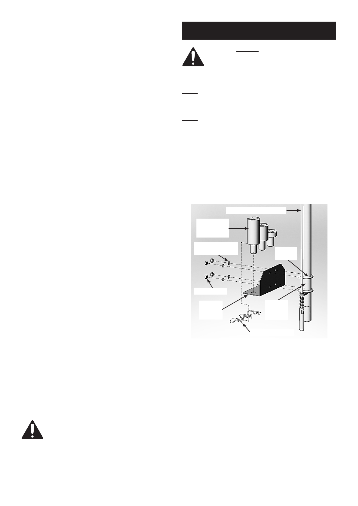
2. Attach Adapter Holder (12.5) to the Outside Tube
(6.1) of the Handle Assembly with two U-Bolts (12.6),
Lock Washers (12.7) and Nuts (12.8).
See Figure 1, below.
Adjustable Rod (6.3)
Adapters
(12.1, 12.3,
12.4)
Spring Washers
(12.7)
Nuts (12.8)
U-Bolts
(12.6)
23. Do not allow anyone in vehicle
when using Bottle Jack.
24. Do not use Bottle Jacks to lift both ends
of a vehicle at the same time.
25. Before lowering the Bottle Jack, make sure
tool trays, jack stands, and all other tools and
equipment are removed from under the vehicles.
26. The warnings, precautions, and instructions
discussed in this manual cannot cover all
possible conditions and situations that may occur.
The operator must understand that common sense
and caution are factors, which cannot be built into
this product, but must be supplied by the operator.
SAVE THESE
INSTRUCTIONS
Adapter
Holder
(12.5)
3. Tighten Nuts to secure Adapter Holder to Handle.
4. Put height adjustment Adapters into the Adapter
bracket and lock each with a Hitch Pin (12.9).
See Figure 1.
Outside
Tube
(6.1)
Hitch Pin (12.9)
Fig. 1
Page 4 For technical questions, please call 1-800-444-3353. SKU 66242
Page 5

5. Put the Handle Assembly into Handle Socket and
secure with Set Screw. See Figure 2, below.
Completed Handle
Fig. 2
Set Screw
(2.5)
2. Attach an air hose to the compressor’s air outlet.
Connect the air hose to the Air Valve Assembly (5)
of the Bottle Jack. Other components, such
as a connector and quick coupler, will make
operation more efcient, but are not mandatory.
WARNING! TO PREVENT SERIOUS INJURY
FROM ACCIDENTAL OPERATION:
Do not install a female quick coupler on the tool.
Such a coupler contains an air valve that will
allow the air tool to retain pressure and operate
accidentally after the air supply is disconnected.
Note: Air ow, and therefore tool performance, can
be hindered by undersized air supply components.
The air hose must be long enough to reach
the work area with enough extra length to
allow free movement while working.
3. Turn the tool’s throttle or switch to the off position;
refer to Operation section for description of controls.
Air Supply
TO PREVENT SERIOUS INJURY
FROM EXPLOSION:
Use only clean, dry, regulated, compressed
air to power this tool. Do not use oxygen,
carbon dioxide, combustible gases, or any other
bottled gas as a power source for this tool.
1. Incorporate a lter, regulator with pressure gauge,
oiler, in-line shutoff valve, and quick coupler for
best service, as shown on Figure A on page 6
and Figure B on page 7. An in-line shutoff
ball valve is an important safety device because
it controls the air supply even if the air hose
is ruptured. The shutoff valve should be a
ball valve because it can be closed quickly.
Note: If an automatic oiler system is not used,
add a few drops of Pneumatic Tool Oil to the
airline connection before operation. Add a few
more drops after each hour of continual use.
4. Close the in-line shutoff valve between
the compressor and the tool.
5. Turn on the air compressor according to
the manufacturer’s directions and allow it
to build up pressure until it cycles off.
6. Adjust the air compressor’s output regulator
so that the air output is enough to properly
power the tool, but the output will not exceed
the tool’s maximum air pressure at any time.
Adjust the pressure gradually, while checking the
air output gauge to set the right pressure range.
7. Inspect the air connections for leaks.
Repair any leaks found.
8. If the tool will not be used at this time, turn off
and detach the air supply, safely discharge any
residual air pressure, and release the throttle
and/or turn the switch to its off position
to prevent accidental operation.
Note: Residual air pressure should not be present
after the tool is disconnected from the air supply.
However, it is a good safety measure to attempt to
discharge the tool in a safe fashion after disconnecting
to ensure that the tool is disconnected and unpowered.
Page 5For technical questions, please call 1-800-444-3353.SKU 66242
Page 6

F
C
E
A
D
E H
A
C
G
Figure A: Portable Air Supply Setup
B
Lubricated
Tools
A
B
Non-lubricated
Tools
Description Function
A Air Hose Connects air to tool
B Filter Prevents dirt and condensation from damaging tool or work piece
C Regulator Adjusts air pressure to tool
F Leader Hose (optional) Increases coupler life
E Coupler and Plug Provides quick connection and release
D Lubricator (optional) For air tool lubrication
H Air Adjusting Valve (optional) For ne tuning airow at tool
G Air Cleaner / Dryer (optional) Prevents water vapor from damaging work piece
Page 6 For technical questions, please call 1-800-444-3353. SKU 66242
Page 7

F
M
L
L O
H
Slope
Lubricated
Figure B: Stationary Air Supply Setup
J
Tools
G
H
K
C
E
D
J
N
I
I
C
Non-lubricated
Tools
F
F
Description Function
C
B B
A A
I Filter Prevents dirt and condensation from damaging tool or work piece
J Regulator Adjusts air pressure to tool
A Vibration Pads For noise and vibration reduction
B Anchor Bolts Secures air compressor in place
C Ball Valve Isolates sections of system for maintenance
F Ball Valve To drain moisture from system
E Main Air Line - 3/4” minimum recommended Distributes air to branch lines
D Isolation Hose For vibration reduction
H Air Hose Connects air to tool
G Branch Air Line -1/2” minimum recommended Brings air to point of use
L Coupler and Plug Provides quick connection and release
K Lubricator (optional) For air tool lubrication
N Air Cleaner / Dryer (optional) Prevents water vapor from damaging work piece
O Air Adjusting Valve (optional) For ne tuning airow at tool
M Leader Hose (optional) Increases coupler life
Page 7For technical questions, please call 1-800-444-3353.SKU 66242
Page 8

Operation
Read the ENTIRE IMPORTANT
SAFETY INFORMATION section at the
beginning of this manual including
all text under subheadings therein
before set up or use of this product.
Inspect tool before use, looking for
damaged, loose, and missing parts.
If any problems are found,
do not use tool until repaired.
To Raise the Vehicle Manually
Before use, park vehicle on a at, level, solid,
surface safely away from oncoming trafc.
Turn off the vehicle’s engine. Place the vehicle’s
transmission in “PARK” (if automatic) or in its lowest
gear (if manual). Set the vehicle’s emergency brake.
Then, chock the wheels that are not being lifted.
1. Pump the Handle Assembly until the top of the Bottle
Jack’s Saddle (1.2) has nearly reached the vehicle
lifting point. The Jack should be positioned at 90° to
the vehicle’s lifting point to ensure the Bottle Jack’s
Saddle and vehicle lifting point are in alignment.
If not, remove and reposition the Jack before lifting.
3. To lift the vehicle, continue to depress the
Lever on the Air Valve Assembly (5). Once the
vehicle is lifted, place the Lock Lever of the Air
Valve Assembly (5) in its locked position.
4. Once the vehicle is raised, slide a jack stand
(not included) to proper lifting point referred
to in vehicle manufacturer’s manual. If using
two jack stands, make sure they are at same
point on each side of the vehicle. Always raise
the vehicle the least amount possible.
5. Slightly lower the Jack to ease the vehicle onto the
jack stands. Do this by slowly turning the Knob (6.11)
counterclockwise until the Saddle (1.2) lowers slightly.
6. When the repair work to the vehicle is completed, and
prior to lowering the vehicle. Make sure to remove all
tools, old vehicle parts, etc. from under the vehicle.
To Lower the Vehicle Manually
1. Turn Knob (6.11) assembly completely clockwise
to close the Release Valve Screw (3.23).
Pump the Handle assembly to raise the
vehicle slightly above the saddle(s) of
the jack stand(s). Then remove the jack
stand(s) from under the vehicle.
2. To lift the vehicle, pump the Handle
assembly using smooth, full strokes.
To Raise the Vehicle
Using Compressed Air
Note: Safety shutoff prevents lifting
in excess of rated load.
1. Turn Knob (6.11) assembly completely clockwise
to its locked position. Then connect an air hose
(not included) to the Air Valve Assembly (5).
2. Depress the Lever of Air Valve Assembly (5)
until the Saddle of the Bottle Jack has nearly
reached the vehicle lifting point. The Jack should
be positioned at 90° to the vehicle’s lifting point
to ensure the Bottle Jack’s Saddle and vehicle
lifting point are in alignment. If not, remove and
then reposition the Bottle Jack before lifting.
2. Slowly turn Knob (6.11) assembly counterclockwise
(never more than one full turns) to lower the vehicle.
To Raise/Lower the Vehicle
Using Compressed Air
1. Turn Knob (6.11) assembly completely clockwise
closing the Release Valve Screw (3.21).
Release the Lock Lever on the Air Valve
Assembly (5). Depress the Lever on the Air Valve
Assembly (5) to raise the vehicle slightly above
the saddle(s) of the jack stand(s). Place the
Lock Lever in its locked position. Then remove
the jack stand(s) from under the vehicle.
2. Slowly turn Knob (6.11) assembly counterclockwise
(never more than one full turn) to lower the vehicle.
Page 8 For technical questions, please call 1-800-444-3353. SKU 66242
Page 9

Inspection, Maintenance, & Cleaning
Procedures not specically explained in this
manual must be performed only by a
qualied technician.
To prevent serious injury from tool failure:
Do not use damaged equipment.
If abnormal noise or vibration occurs, have
the problem corrected before further use.
1. BEFORE EACH USE, inspect the general condition
of the Bottle Jack. Check for loose screws,
misalignment or binding of moving parts, cracked
or broken parts, damaged Air Hose, and any other
condition that may affect its safe operation.
2. AFTER USE, clean external surfaces of the
Bottle Jack with a clean, moist cloth and a
mild detergent. Do not use solvents.
Bleeding Instructions
Before each use or if Bottle Jack performance decreases,
check for excessive air and proper hydraulic oil
level in Bottle Jack. If Jack appears not to be
working properly, it may be necessary to purge its
hydraulic system of excessive air as follows:
1. Turn Knob (6.11) Assembly completely clockwise,
closing the Release Valve Screw (3.21).
Pump the handle up and down quickly 5-6 times.
Then turn the Knob (6.11) 1-1/2 turns
counterclockwise, releasing pressure.
2. Remove the Filler Plug (1.19), and ll the Cylinder
Base (1.14) reservoir with hydraulic oil (not included).
3. Rapidly pump Handle several times to purge air.
4. Turn Knob (6.11) clockwise until
snug to hold pressure.
5. Top off the reservoir with hydraulic oil.
Then replace the Filler Plug (1.19).
IMPORTANT: After bleeding the Bottle Jack, test the
Jack for proper operation prior to its actual use.
NOTE: To prevent damage to the Bottle Jack, check
for excessive air and/or low hydraulic oil regularly.
6. WHEN STORING, turn Lock Lever (6.5)
to its open position (counterclockwise).
Always store the Bottle Jack and its accessories
in a clean, dry, safe location out of reach of
children and other unauthorized people.
TO PREVENT SERIOUS INJURY AND DEATH:
Use caution when troubleshooting a malfunctioning jack.
Stay well clear of the supported load. Completely
resolve all problems before use. If the solutions
presented in the Troubleshooting guide do not
solve the problem, have a qualied technician
inspect and repair the jack before use.
After the jack is repaired: Test it carefully
without a load by raising and lowering it fully,
checking for proper operation, BEFORE
RETURNING THE JACK TO OPERATION.
DO NOT USE A DAMAGED OR MALFUNCTIONING JACK!
POSSIBLE SYMPTOMS
Jack will
not lift at
its weight
capacity
Saddle
lowers
under
load
Pump
stroke
feels
spongy
Saddle
will not
lift all the
way
X X
X X X
X
X X
Handle
moves up
when jack
is under
load
Oil leaking
from ller
plug
X
(Make certain that the jack is not supporting
PROBABLE SOLUTION
a load while attempting a solution.)
Check that Release Valve is fully closed.
Bleed air from the system.
Valves may be blocked and may not
close fully. To ush the valves:
1. Lower the Saddle and securely
close the Release Valve.
2. Manually lift the saddle several inches.
3. Open the release valve and force the
saddle down as quickly as possible.
Jack may be low on oil.
Check the oil level and rell if needed.
Jack may require bleeding see instructions above.
Unit may have too much
hydraulic oil inside, check uid
level and adjust if needed.
Page 9For technical questions, please call 1-800-444-3353.SKU 66242
Page 10

PLEASE READ THE FOLLOWING CAREFULLY
THE MANUFACTURER AND/OR DISTRIBUTOR HAS PROVIDED THE PARTS DIAGRAM IN THIS MANUAL
AS A REFERENCE TOOL ONLY. NEITHER THE MANUFACTURER NOR DISTRIBUTOR MAKES ANY
REPRESENTATION OR WARRANTY OF ANY KIND TO THE BUYER THAT HE OR SHE IS QUALIFIED TO
MAKE ANY REPAIRS TO THE PRODUCT OR THAT HE OR SHE IS QUALIFIED TO REPLACE ANY PARTS
OF THE PRODUCT. IN FACT, THE MANUFACTURER AND/OR DISTRIBUTOR EXPRESSLY STATES
THAT ALL REPAIRS AND PARTS REPLACEMENTS SHOULD BE UNDERTAKEN BY CERTIFIED AND
LICENSED TECHNICIANS AND NOT BY THE BUYER. THE BUYER ASSUMES ALL RISK AND LIABILITY
ARISING OUT OF HIS OR HER REPAIRS TO THE ORIGINAL PRODUCT OR REPLACEMENT PARTS
THERETO, OR ARISING OUT OF HIS OR HER INSTALLATION OF REPLACEMENT PARTS THERETO.
Parts List
Part Description
1.1 Cover
1.2 Saddle
1.3 Extension Screw
1.3a Spring Pin
1.4 Spring Support
1.5 Screw Bushing
1.6 Y-Shape Seal Ring
1.7 Head Nut
1.8 O-Ring
1.9 Piston Rod
1.10 Stop Ring
1.11 U-Shape Seal Ring
1.12 Piston Head
1.13 Elastic Stop Ring
1.14 Cylinder
1.15 Spring
1.16 Nut
1.17 Screw
1.18 O-Ring
1.19 Filler Plug
1.20 Screw
1.21 Washer
1.22 O-Ring
1.23 O-Ring
1.24 O-Ring
1.25 Chassis Base
2.1 Side Plate
2.2 Angle Bracket
2.3 Handle Fork
2.4 Washer
2.5 Set Screw
2.6 Washer
2.7 Bolt
2.8 Wheel
2.9 Washer
2.10 Track Ring
Part Description
2.11 Washer
2.12 Screw
2.14 Screw
2.15 Washer
2.16 Bolt
2.17 Washer
3.1 Screw
3.2 Washer
3.3 Spring
3.4 Steel Ball
3.5 Valve Core
3.6 Spring
3.7 Steel Ball
3.8 Cylinder Base
3.9 Steel Ball
3.10 Valve
3.11 Spring
3.13 Screw
3.14 O-Ring
3.15 Screw
3.16 Pump Body
3.17 Washer
3.18 O-Ring
3.19 Release Valve Body
3.20 Steel Ball
3.21 O-Ring
3.23 Release Valve Screw
3.24 Washer
3.25 Stop Ring
3.26 Fork Axle With Hole
3.27 Steel Wire
3.28 Connecting Block
3.29 Spring Pin
3.30 Spring Pin
3.31 Fork Axle
3.32 Pin
Part Description
3.33 Joint
3.34 Steel Wire
3.35 Connecting Block
3.36 Fork Axle With Hole
3.37 Spring Pin
3.38 Spring Pin
3.39 Connecting Axle
3.40 Spring Pin
4 Air Pump
4.1 Packing
4.35 Rubber Hose
4.36 Spring
5 Air Valve Assembly
5.2 Filter Nozzle
6.1 Outside Tube
6.2 Spring
6.3 Adjustable Rod
6.4 Split Pin
6.5 Lock Lever
6.6 Spring Pin
6.7 Hex Screw
6.8 Handle
6.9 Control Rod
6.10 Spring Pin
6.11 Knob
6.15 Handle Cap
12.1 Adapter-A
12.3 Adapter-C
12.4 Adapter-D
12.5 Adapter Holder
12.6 U-Bolt
12.7 Spring Washer
12.8 Nut
12.9 Hitch Pin
Record Product’s Serial Number Here:
Note: If product has no serial number, record
month and year of purchase instead.
Page 10 For technical questions, please call 1-800-444-3353. SKU 66242
Note: Some parts are listed and shown for
illustration purposes only, and are not available
individually as replacement parts.
Page 11

Assembly Diagram
1.1
1.2
1.4
1.15
1.6
1.5
1.8
1.7
1.3
1.3A
1.9
1.10
1.11
1.12
1.13
1.18
1.19
1.16
1.14
2.17 2.14
3.1
3.2
3.3
3.4
3.5
3.6
3.7
3.15
3.14
3.13
3.11
3.10
3.8
3.19
3.17
3.20
3.18
4.1
1.22
1.23
12.8 12.7
3.23 3.24
3.21
3.25
3.26
3.27
12.412.112.312.9
12.5
3.29 3.32
3.31
3.28
3.33
3.38
3.34
3.36
6.9
3.35
3.40
3.37
3.39
2.2
6.8
4
2.3
6.4
2.5
2.4
6.1
12.6
6.2
6.11
6.10
6.3
6.56 .5B
6.6
6.7
6.15
5
5.2
4.36
4.35
1.17
1.21
1.20
2.1
2.11
2.12
2.15 2.16
1.25
2.15 2.16
2.6
2.7
2.6
2.7
2.11 2.12
2.8
2.9
2.10
Page 11For technical questions, please call 1-800-444-3353.SKU 66242
Page 12

90 Day Warranty
Harbor Freight Tools Co. makes every effort to assure
that its products meet high quality and durability
standards, and warrants to the original purchaser
that this product is free from defects in materials and
workmanship for the period of 90 days from the date
of purchase. This warranty does not apply to damage
due directly or indirectly, to misuse, abuse, negligence
or accidents, repairs or alterations outside our facilities,
criminal activity, improper installation, normal wear and
tear, or to lack of maintenance. We shall in no event
be liable for death, injuries to persons or property, or
for incidental, contingent, special or consequential
damages arising from the use of our product. Some
states do not allow the exclusion or limitation of incidental
or consequential damages, so the above limitation of
exclusion may not apply to you. THIS WARRANTY IS
EXPRESSLY IN LIEU OF ALL OTHER WARRANTIES,
EXPRESS OR IMPLIED, INCLUDING THE
WARRANTIES OF MERCHANTABILITY AND FITNESS.
To take advantage of this warranty, the product or part
must be returned to us with transportation charges
prepaid. Proof of purchase date and an explanation
of the complaint must accompany the merchandise. If
our inspection veries the defect, we will either repair
or replace the product at our election or we may elect
to refund the purchase price if we cannot readily and
quickly provide you with a replacement. We will return
repaired products at our expense, but if we determine
there is no defect, or that the defect resulted from
causes not within the scope of our warranty, then
you must bear the cost of returning the product.
This warranty gives you specic legal rights and you may
also have other rights which vary from state to state.
3491 Mission Oaks Blvd. • PO Box 6009 • Camarillo, CA 93011 • (800) 444-3353
www.harborfreight.com
 Loading...