

Page 1
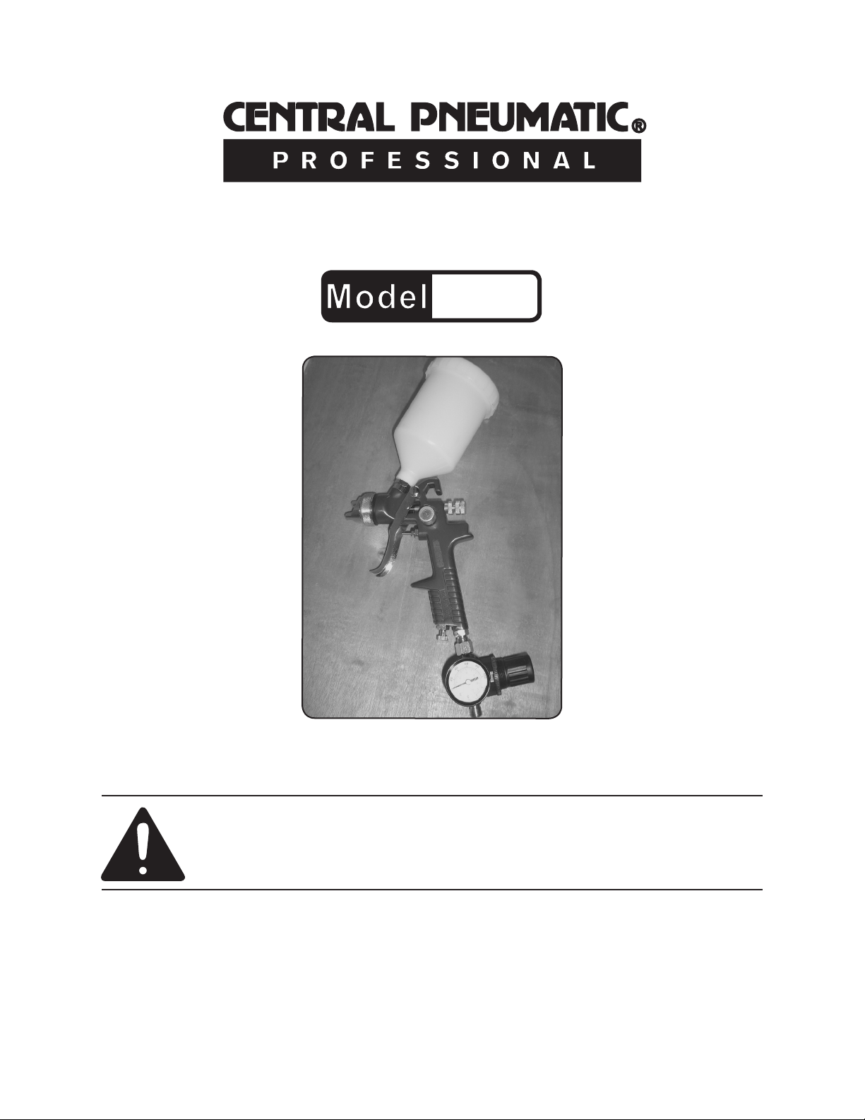
HVLP GRAVITY FEED
SPRAY GUN
66222
SET UP AND OPERATING INSTRUCTIONS
Distributed exclusively by Harbor Freight Tools®.
3491 Mission Oaks Blvd., Camarillo, CA 93011
Visit our website at: http://www.harborfreight.com
Read this material before using this product.
Failure to do so can result in serious injury.
SAVE THIS MANUAL.
Copyright© 2008 by Harbor Freight Tools®. All rights reserved. No portion of this manual or any artwork
contained herein may be reproduced in any shape or form without the express written consent of
Harbor Freight Tools. Diagrams within this manual may not be drawn proportionally. Due to continuing
improvements, actual product may differ slightly from the product described herein. Tools required for
assembly and service may not be included.
For technical questions or replacement parts, please call 1-800-444-3353.
Page 2
SAVE THIS MANUAL
Keep this manual for the safety warnings and precautions, assembly, operating, inspection, maintenance and cleaning
procedures. Write the product’s serial
number in the back of the manual near the
assembly diagram (or month and year of
purchase if product has no number). Keep
this manual and the receipt in a safe and
dry place for future reference.
CAUTION, used
with the safety
alert symbol,
indicates a hazardous
situation which, if not
avoided, could result in minor
or moderate injury.
NOTICE is used to
address practices
not related to
personal injury.
Safety Alert Symbol and Signal
Words
In this manual, on the labeling,
and all other information provided with this product:
This is the safety alert
symbol. It is used to alert
you to potential personal
injury hazards. Obey all
safety messages that
follow this symbol to avoid
possible injury or death.
DANGER indicates
a hazardous
situation which, if
not avoided, will result in
death or serious injury.
WARNING
indicates a
hazardous
situation which, if not
avoided, could result in death
or serious injury.
CAUTION, without
the safety alert
symbol, is used to
address practices not related
to personal injury.
IMPORTANT SAFETY
INSTRUCTIONS
INSTRUCTIONS PERTAINING
TO A RISK OF FIRE,
ELECTRIC SHOCK, OR
INJURY TO PERSONS
WARNING – When using tools, basic pre-
cautions should always be followed,
including the following:
General
To reduce the risks of electric shock,
re, and injury to persons, read all the
instructions before using the tool.
Work area
Keep the work area clean and well a.
lighted. Cluttered benches and dark
areas increase the risks of electric
shock, re, and injury to persons.
SKU 66222 For technical questions, please call 1-800-444-3353. Page 2
Page 3
Remove or cover objects from the b.
area that you want to protect from
overspray or paint dust.
Operate only in a well-ventilated c.
area. Paint thinners and solvents
may be harmful if breathed. Always
wear an ANSI approved ventilator
when painting.
trigger or connect the tool to the air
supply with the trigger on.
Do not overreach. Keep proper d.
footing and balance at all times.
Proper footing and balance enables
better control of the tool in unexpected situations.
Do not operate the tool in explo-d.
sive atmospheres, such as in the
presence of ammable liquids,
gases, or dust. The tool is able to
create sparks resulting in the ignition
of the dust or fumes.
Keep bystanders, children, and e.
visitors away while operating the
tool. Distractions are able to result in
the loss of control of the tool.
Personal safety
Stay alert. Watch what you are do-a.
ing and use common sense when
operating the tool. Do not use the
tool while tired or under the inuence of drugs, alcohol, or medication. A moment of inattention while
operating the tool increases the risk
of injury to persons.
Dress properly. Do not wear loose b.
clothing or jewelry. Contain long
hair. Keep hair, clothing, and
gloves away from moving parts.
Loose clothes, jewelry, or long hair
increases the risk of injury to persons
as a result of being caught in moving
parts.
Avoid unintentional starting. Be c.
sure the trigger is off before connecting to the air supply. Do not
carry the tool with your nger on the
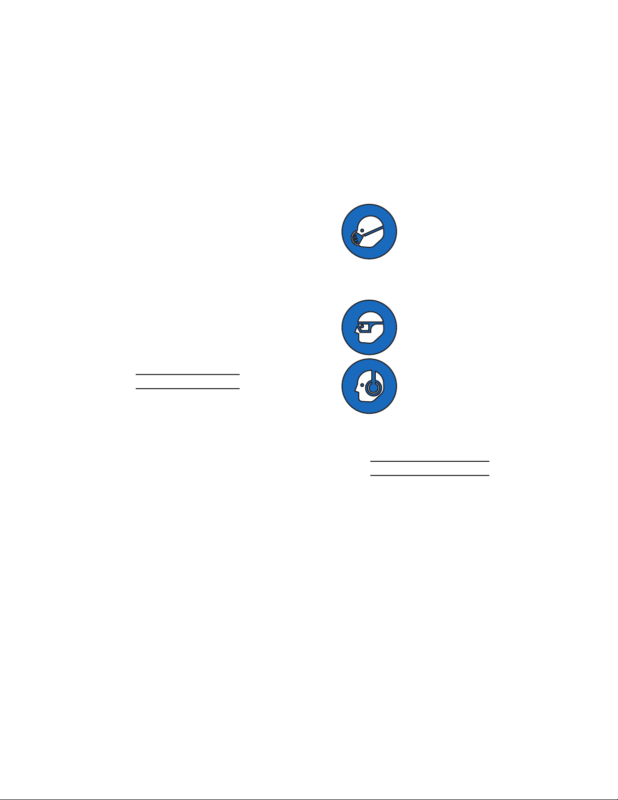
e. Use safety equipment. A
dust mask, non-skid safety
shoes and a hard hat must
be used for the applicable
conditions. Wear protec-
tive work gloves during use.
f. Always wear eye protec-
tion. Wear ANSI-approved safety goggles.
g. Always wear hearing
protection when using
the tool. Prolonged expo-
sure to high intensity noise
is able to cause hearing
loss.
Tool use and care
Use clamps or another practical a.
way to secure and support the
work piece to a stable platform.
Holding the work by hand or against
the body is unstable and is able to
lead to loss of control.
Do not force the tool. b. Use the
correct tool for the application. The
correct tool will do the job better and
safer at the rate for which the tool is
designed.
Do not use the tool if the trigger c.
does not turn the tool on or off.
Any tool that cannot be controlled
SKU 66222 For technical questions, please call 1-800-444-3353. Page 3
Page 4

with the trigger is dangerous and
must be repaired.
Disconnect the tool from the air d.
source before making any adjustments, changing accessories, or
storing the tool. Such preventive
safety measures reduce the risk of
starting the tool unintentionally. Turn
off and detach the air supply, safely
discharge any residual air pressure,
and release the throttle and/or turn
the trigger to its off position before
leaving the work area.
Store the tool when it is idle out of e.
reach of children and other untrained persons. A tool is dangerous
in the hands of untrained users.
Maintain the tool with care. f. Keep a
cutting tool sharp and clean. A properly maintained tool, with sharp cutting edges reduces the risk of binding
and is easier to control.
Check for misalignment or bind-g.
ing of moving parts, breakage of
parts, and any other condition that
affects the tool’s operation. If dam-
aged, have the tool serviced before
using. Many accidents are caused
by poorly maintained tools. There is a
risk of bursting if the tool is damaged.
When servicing a tool, use only b.
identical replacement parts. Use
only authorized parts.
Use only the lubricants supplied c.
with the tool or specied by the
manufacturer.
Air source
a. Never connect to an air
source that is capable of
exceeding 100 psi. Over
pressurizing the tool may
cause bursting, abnormal
operation, breakage of the tool or
serious injury to persons. Use only
clean, dry, regulated compressed air
at the rated pressure or within the
rated pressure range as marked on
the tool. Always verify prior to using
the tool that the air source has been
adjusted to the rated air pressure or
within the rated air-pressure range.
Never use oxygen, carbon dioxide, b.
combustible gases or any bottled
gas as an air source for the tool.
Such gases are capable of explosion
and serious injury to persons.
SAVE THESE
INSTRUCTIONS.
Use only accessories that are h.
identied by the manufacturer for
the specic tool model. Use of an
accessory not intended for use with
the specic tool model, increases the
risk of injury to persons.
Service
Tool service must be performed a.
only by qualied repair personnel.
SKU 66222 For technical questions, please call 1-800-444-3353. Page 4
Page 5
SYMBOLS AND
SPECIFIC SAFETY
INSTRUCTIONS
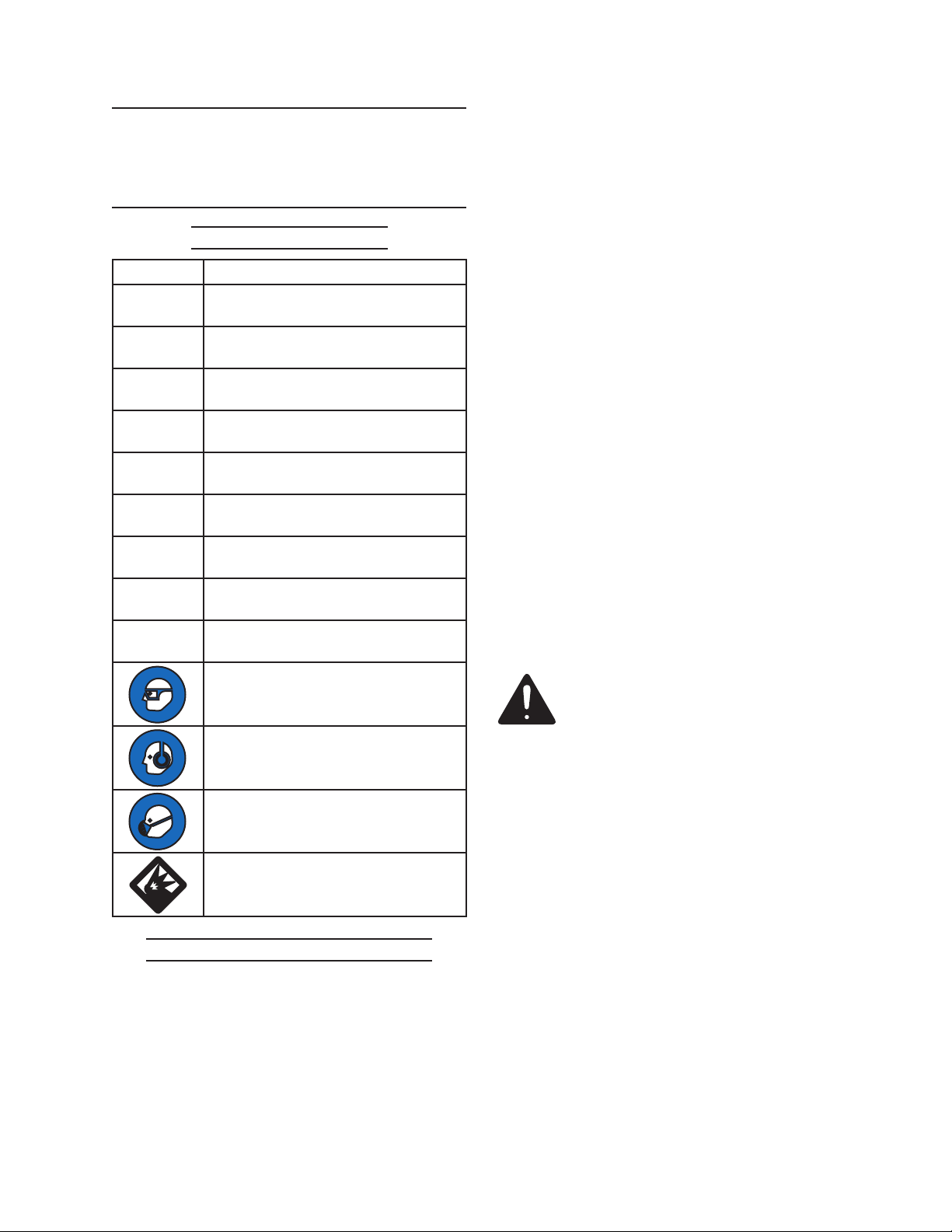
Symbol Denitions
Symbol Property or statement
n
o
.../min
PSI
ft-lb
BPM
No-load speed
Revolutions or reciprocation per
minute
Pounds per square inch of pressure
Foot-pounds of torque
Blows per minute
cannot be built into this product, but
must be supplied by the operator.
WARNING: The brass components 2.
of this product contain lead, a chemical known to the State of California
to cause birth defects (or other reproductive harm). (California Health &
Safety code § 25249.5, et seq.)
Only use with accessories rated to 3.
handle the forces exerted by this tool
during operation.
Attach all accessories properly to the 4.
tool before connecting the air supply. A loose accessory may detach or
break during operation.
CFM
SCFM
NPT
NPS
Cubic Feet per Minute ow
Cubic Feet per Minute ow at
standard conditions
National pipe thread, tapered
National pipe thread, straight
WARNING marking concerning Risk
of Eye Injury. Wear ANSI-approved
eye protection.
WARNING marking concerning Risk
of Hearing Loss. Wear hearing
protection.
WARNING marking concerning Risk
of Respiratory Injury. Wear NIOSH-
approved dust mask/respirator.
WARNING marking concerning Risk
of Explosion.
Specic Safety Instructions
Obey the manual for the air compres-5.
sor used to power this tool.
Install an in-line shutoff valve to allow 6.
immediate control over the air supply
in an emergency, even if a hose is
ruptured.
SAVE THESE
INSTRUCTIONS.
The warnings and precautions dis-1.
cussed in this manual cannot cover
all possible conditions and situations
that may occur. It must be understood by the operator that common
sense and caution are factors which
SKU 66222 For technical questions, please call 1-800-444-3353. Page 5
Page 6
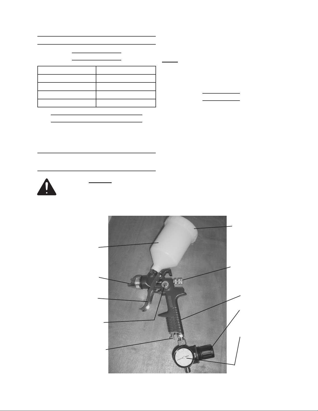
FUNCTIONAL DESCRIPTION
subheadings therein before set
up or use of this product.
Specications
Air Pressure Range 15-45 PSI
Maximum Air Pressure 45 PSI
Air Inlet 1/4” -18 NPS
Air Consumption 12 SCFM @ 45 PSI
Paint Cup Capacity 20 FL. OZ.
Components and Controls
Please refer to the photo on this page for
important components and controls.
INITIAL TOOL SET UP/
ASSEMBLY
Read the ENTIRE IMPORTANT
SAFETY INFORMATION
section at the beginning of this
manual including all text under
Note: For additional information regarding
the parts listed in the following pages,
refer to the Assembly Diagram near
the end of this manual.
Unpacking
When unpacking, check to make sure
that the item is intact and undamaged. If
any parts are missing or broken, please
call Harbor Freight Tools at the number
shown throughout the manual as soon as
possible.
This air tool may be shipped with a •
protective plug covering the air inlet.
Remove this plug before set up.
Cup (28)
Air Cap (1)
Trigger (36)
Spray Regulator (20)
Air Adjustment Valve (31)
Lid (29)
Fluid Control
Knob (12)
Gun Body (8)
Air Regulator (37)
Air Pressure
Gauge (38)
SKU 66222 For technical questions, please call 1-800-444-3353. Page 6
Page 7

Air Supply
TO PREVENT
EXPLOSION:
Use only clean,
dry, regulated, compressed air
to power this tool. Do not use
oxygen, carbon dioxide,
combustible gases, or any
other bottled gas as a power
source for this tool.
Do not install a female quick
coupler on the tool. Such a coupler
contains an air valve that will allow
the air tool to retain pressure and
operate accidentally after the air
supply is disconnected.
Note: Air ow, and therefore tool perfor-
mance, can be hindered by undersized air supply components.
The air hose must be long enough 3.
to reach the work area with enough
extra length to allow free movement
while working.
Make sure the tool’s trigger is in the 4.
off position; refer to Operation section
for description of controls.
Close the in-line safety valve be-5.
tween the compressor and the tool.
1. Incorporate a shut-off valve, regula-
tor with pressure gauge, and lter
for best service, as shown in the
diagram above. An in-line shutoff
valve is an important safety device
because it controls the air supply
even if the air hose is ruptured.
Attach an air hose to the compres-2.
sor’s air outlet. Connect the air hose
to the air inlet of the tool. Other components, such as a connector and
quick coupler, will make operation
more efcient, but are not required.
WARNING! TO PREVENT SERIOUS
INJURY FROM ACCIDENTAL
OPERATION:
Turn on the air compressor according 6.
to the manufacturer’s directions and
allow it to build up pressure until it
cycles off.
Adjust the air compressor’s output 7.
regulator so that the air output is
enough to properly power the tool,
but the output will not exceed the
tool’s maximum air pressure at any
time. Adjust the pressure gradually,
while checking the air output gauge
to set the right pressure range.
Inspect the air connections for leaks. 8.
Repair any leaks found.
If the tool will not be used at this 9.
time, turn off and detach the air supply, safely discharge any residual air
pressure, and release the throttle
and/or turn the trigger to its off position to prevent accidental operation.
SKU 66222 For technical questions, please call 1-800-444-3353. Page 7
Page 8

Note: Residual air pressure should not be
present after the tool is disconnected
from the air supply. However, it is a
good safety measure to attempt to
discharge the tool in a safe fashion
after disconnecting to ensure that the
tool is disconnected and unpowered.
OPERATING INSTRUCTIONS
Read the ENTIRE IMPORTANT
SAFETY INFORMATION
section at the beginning of this
manual including all text under
subheadings therein before set
up or use of this product.
Air powered HVLP and conventional 4.
spray guns differ from airless spray-
ers that are uid powered.
Airless sprayers use a uid pump to 5.
force the paint through the gun to the
spray cap. The uid pressure at the
cap atomizes the paint causing the
spray.
Airless sprayers do not require an air 6.
compressor to operate as do HVLP
and conventional sprayers. However,
since the paint is pumped under pressure through the gun, airless spray-
ers are more difcult to clean and
maintain than HVLP sprayers.
Inspect tool before use, looking
for damaged, loose, and
missing parts. If any problems
are found, do not use tool until
repaired.
Understanding HVLP
HVLP Spray Guns are different from 1.
conventional spray guns and airless
sprayers.
HVLP stands for High Volume Low 2.
Pressure. This means that HVLP
guns will spray a larger amount of
paint at lower Cap Pressure than
conventional air powered spray guns.
Cap Pressure is the amount of air 3.
pressure present at the Spray Cap
(1). Lower pressure results in less
paint being air dried between the
gun and the work surface, and less
bounce back from the work surface.
You will achieve a smoother painted
surface with less waste and overspray than with a conventional air
powered spray gun.
If you have compressed air available, 7.
HVLP spray guns will provide a better
nish with less paint waste and less
required maintenance that conventional or airless sprayers.
Paint bounce back
comparison.
SKU 66222 For technical questions, please call 1-800-444-3353. Page 8
Page 9

Tool Set Up
TO PREVENT
SERIOUS INJURY
FROM
ACCIDENTAL OPERATION:
Turn off the tool, detach the
air supply, safely discharge
any residual air pressure in
the tool, and release the
throttle and/or turn the trigger
to its off position before
performing any inspection,
maintenance, or cleaning
procedures.
TO PREVENT SERIOUS
INJURY:
Do not adjust or tamper with
any control or component in a
way not specically explained
within this manual. Improper
adjustment can result in
tool failure or other serious
hazards.
This tool is treated with anti-corrosive 1.
compounds at the factory. Flush it out
thoroughly with paint thinner before
rst use.
Route the air hose along a safe route 2.
to reach the work area without creating a tripping hazard or exposing the
air hose to possible damage. The air
hose must be long enough to reach
the work area with enough extra
length to allow free movement while
working.
Secure loose work pieces using a 3.
vise or clamps (not included) to prevent movement while working.
There must not be hazardous ob-4.
jects (such as utility lines or foreign
objects) nearby that will present a
hazard while working.
Prepare a well ventilated work space. 5.
Use a ventilator designed to prevent
inhalation of paint and volatile uids
and gasses.
Prepare the paint
Due to the high viscosity of latex and 1.
most water based paints, they are not
generally recommended for HVLP
painting. Check with the paint manu-
facturer for specics.
Before using check all fasteners and 2.
air connections to be sure they are
tight.
To avoid contamination, blow out 3.
the air line before connecting to the
Spray Gun.
Work Piece and
Work Area Set Up
Designate a work area that is clean 1.
and well-lit. The work area must not
allow access by children or pets to
prevent injury and distraction.
SKU 66222 For technical questions, please call 1-800-444-3353. Page 9
In most cases, the paint must be 2.
thinned for spraying. Only use the
thinner recommended by the paint
manufacturer. If the paint is too thick,
you will get a thick, orange-peel nish, and the sprayer may clog. If the
paint is too thin, you will get poor coverage, drips and runs, and excessive
drying of the paint in the air.
Proper thinning varies with the mate-3.
rial being used and local temperature
and humidity. In most cases, thinning
will be approximately 10% and not
more than 30%.
Page 10

Test the paint viscosity by dipping 4.
a stick into the paint, then observing the rate paint drips from the end.
Properly thinned paint will drip about
1 per second.
Follow paint manufacturer’s recom-5.
mendations. Experiment with scrap
material to determine the correct
paint viscosity.
Always strain the paint when pouring 6.
it into the Cup (28). This will prevent
lumps or impurities from clogging the
Fluid Nozzle (2).
Adjust the Air Pressure
Adjust the air pressure by turning the 1.
Knob on the Air Regulator (37). Pull
the Knob out to release, turn to ad-
just, then press back in to lock. The
air pressure setting can be read on
the Air Pressure Gauge (38). The recommended pressure is 15 to 45 PSI.
CAUTION! TO PREVENT TOOL
AND ACCESSORY FAILURE, RESULTING IN INJURY:
Do not exceed the tool’s maximum
air pressure rating.
Air pressure can be ne adjusted us-2.
ing the Air Adjustment Valve (31). Air
pressure too high will cause splattering, too low will cause drizzling.
Adjust the Paint Volume
The amount of paint being sprayed 1.
can be adjusted with the Fluid Control Knob (12). To adjust, release the
Lock Nut (11) by turning it slightly
counterclockwise.
squeeze the Trigger (36) all the way.
With the Trigger squeezed, turn the
Fluid Control Knob (12) counterclock-
wise to increase paint ow.
When the paint pattern is smooth, 3.
lock the setting by turning the Locknut (11) clockwise.
Adjusting the
Fan Direction and Pattern
The fan shaped spray direction of the 1.
paint can be adjusted by turning the
Air Cap (1). Loosen the lock ring, turn
the Air Cap as needed then retighten
the lock ring.
When spraying in a horizontal motion, 2.
have the Air Cap (1) turned horizontally
to have a vertical fan. When spraying
up and down, have the Air Cap turned
vertically to have a horizontal fan.
The spray pattern can be adjusted 3.
by turning the Spray Regulator (20).
Turning the knob counterclockwise
will open and atten the pattern.
Turning it clockwise will close the pattern making it more round.
Turn the Fluid Control Knob (12) 2.
all the way clockwise to turn off
paint ow. Using a scrap material,
SKU 66222 For technical questions, please call 1-800-444-3353. Page 10
Page 11

Practice on scrap material until the 4.
desired pattern is achieved.
a paint lm. The paint lm chemically
bonds together.
Understanding
Paint Thinners and Solvents
Understand the difference between a 1.
paint “thinner” and a paint “solvent”. A
thinner is used to thin the paint while
it is wet. A solvent is used to dissolve
the paint after it has dried.
Paint Type Thinner Solvent
Latex Water Paint Remover
Water
Based
Paint
Oil Varnish
or Paint
Lacquer Lacquer
Shellac Alcohol Alcohol
There are basically three types of 2.
paint: evaporative, chemical and
coagulating.
Evaporative paints cure when the 3.
solvent evaporates. These are quick
drying paints, including lacquer and
shellac.
Chemical paints cure when there is 4.
a chemical reaction solidifying the
paint, as the solvent evaporates. Oilbased paint and varnish are of this
type. They are relatively slow drying,
and may cure over months or years.
Coagulating paint such as latex and 5.
water based nishes are composed
of bits of paint suspended in water.
As the water evaporates the bits of
paint adhere to each other and form
Water Paint Remover
Mineral
Spirits,
Turpentine
Thinner
Paint Remover
Lacquer Thinner
While the paint is wet, before it has 6.
dried, you can thin or clean away the
paint using a thinner.
Once the paint has dried, in most 7.
cases the thinner can no longer be
used. You must then use a solvent to
remove the paint.
Cleaning the paint before it dries, 8.
using a thinner, is much easier than
cleaning the paint after it dries using
a solvent.
Always clean this spray gun immedi-9.
ately after use, before the paint dries.
Use the thinner approved by the
manufacturer for your paint.
Painting Technique
with this HPLV Sprayer
Your goal in painting with this sprayer 1.
is to get good coverage of the work
piece. You want an even coat without drips or runs and with a smooth
surface.
To get an even coat, hold the spray 2.
gun 6 to 8 inches away from the work
surface. Keep the distance of your
gun from the project, as consistent as
possible.
Start spraying slightly off the edge 3.
of the work piece, move the spray
across and end slightly off the work
piece. Overlap each pass across the
work piece. While this method does
create over-spray at the edges, it will
give you an even coat without heavier
or lighter layers at the edge.
SKU 66222 For technical questions, please call 1-800-444-3353. Page 11
Page 12

Do not stop your motion when spray-4.
ing the work piece. Stopping will
cause to build up, and run or sag.
Hold the Spray Gun vertically. Hold-5.
ing the gun at an angle will affect the
spray pattern.
Do not spray too heavily. Heavy spray 6.
will cause drips, sags and runs. Build
up the paint surface with several light
coats. Apply each coat when the
previous one is tacky but not yet dry.
This will allow the over coat to adhere
to the previous layer, but will not be
so heavy as to cause sags, runs or
drips.
You must also avoid thick, clumpy 7.
paint surface called “orange peel”.
Prevent orange peel by thinning the
paint properly before spraying. Then
spray successive light, even coats.
a strainer. Replace the Lid (29) and
screw on tightly.
Put on a ventilator and other safety 5.
equipment recommended in the
Safety Section of this manual.
Point the Sprayer toward the work 6.
material and squeeze the Trigger
(36). Paint will spray.
Move the spray across the work 7.
piece as needed.
When done painting, release the Trig-8.
ger (36). The gun will stop spraying.
The Gun Body (8) has a hook built 9.
into the top for convent hanging during pauses in operation.
When done painting, pour remaining 10.
paint from the Cup (28) into an appropriate container.
Clean the Sprayer thoroughly be-11.
fore putting it away.
To prevent accidents, turn off the 12.
tool, detach the air supply, safely
discharge any residual air pressure
in the tool, and release the throttle
and/or turn the trigger to its off position after use.
Operating the HVLP Sprayer
Cover all items you do not want 1.
painted, using painters plastic or a
drop cloth (not included).
Connect your air supply hose to the 2.
Air Inlet (32).
Adjust the Air Regulator to 15-45 PSI.3.
Fill the Cup (28) with thinned paint. 4.
Remember to pour the paint through
SKU 66222 For technical questions, please call 1-800-444-3353. Page 12
Then store the tool indoors in a safe 13.
place out of children’s reach.
Page 13

USER MAINTENANCE
Cleaning the Sprayer
INSTRUCTIONS
Procedures not specically
explained in this manual
must be performed only by a
qualied technician.
TO PREVENT
SERIOUS INJURY
FROM
ACCIDENTAL OPERATION:
Turn off the tool, detach the
air supply, safely discharge
any residual air pressure in
the tool, and release the
throttle and/or turn the trigger
to its off position before
performing any inspection,
maintenance, or cleaning
procedures.
TO PREVENT SERIOUS
INJURY FROM TOOL
FAILURE:
Do not use damaged
equipment. If abnormal
noise, vibration, or leaking
air occurs, have the problem
corrected before further use.
IMPORTANT: The Spray Gun must 1.
be cleaned every time immediately
after use. Improper cleaning is the
primary cause of Spray Gun failure.
Immediately after nishing painting, 2.
pour out remaining paint from the
Cup. Rinse out the cup with paint
thinner. Wipe out the cup to clean
remaining paint residue. Fill the Cup
part way with paint thinner and spray
into a suitable container. Continue
to spray until the thinner comes out
clear.
Dump remaining thinner from the Cup 3.
back into the thinner container. Wipe
off the exterior of the Spray Gun with
thinner to remove paint.
If the gun becomes clogged, disassemble 4.
parts 1 - 7, 9 -12 and 26 - 30 and carefully
clean all the parts.
To clean, use the enclosed brush (33) 5.
or a cleaning kit, such as SKU# 99634
available from Harbor Freight Tools.
Never use a pin or metal scraper to 6.
clean the delicate components of this
sprayer. You will damage the sprayer.
Cleaning, Maintenance,
and Lubrication
Note: These procedures are in addition to
the regular checks and maintenance
explained as part of the regular operation of the air-operated tool.
SKU 66222 For technical questions, please call 1-800-444-3353. Page 13
Carefully reassemble following the 7.
Assembly diagram on page 17. Be
sure all springs and seals are properly seated. Do not damage threads.
Do not overtighten.
Page 14

Tool Troubleshooting
Problem Possible Causes Likely Solutions
Decreased output. Not enough air pressure 1.
Severe air
leakage.
(Slight air leakage
is normal,
especially on older
tools.)
and/or air ow.
Obstructed trigger. 2.
Blocked air inlet screen (if 3.
equipped).
Air leaking from loose 4.
housing.
Air Regulator set too low.5.
Cross-threaded housing 1.
components.
Loose housing. 2.
Damaged connectors or 3.
housing.
Check for loose connections and make sure 1.
that air supply is providing enough air ow
(CFM) at required pressure (PSI) to the
tool’s air inlet. Do not exceed maximum air
pressure.
Clean around trigger to ensure free 2.
movement.
Clean air inlet screen of buildup. 3.
Make sure housing is properly assembled and 4.
tight.
Adjust Air Regulator setting.5.
Check for incorrect alignment and uneven 1.
gaps. If cross-threaded, disassemble and
replace damaged parts before use.
Tighten housing assembly. If housing cannot 2.
tighten properly, internal parts may be
misaligned.
Replace damaged components.3.
Inconsistent paint
ow, blobs and
splatters
Paint blows out
too hard
Follow all safety precautions whenever diagnosing or servicing the tool.
Disconnect air supply before service.
Clogged Air Cap (1) or 1.
damaged Fluid Nozzle (2).
Clogged Paint Filter (27).2.
Damaged or dirty Paint 3.
Needle (9).
Contaminated paint.4.
Air pressure set too high.1. Adjust Air Regulator to no more than 45 PSI. 1.
Clean , adjust or replace Air Cap or Fluid 1.
Nozzle.
Clean Paint Filter (27).2.
Clean, repair or replace Paint Needle (9). 3.
Remove paint and lter it.4.
Fine tune air pressure using Air Adjustment
Valve (31).
SKU 66222 For technical questions, please call 1-800-444-3353. Page 14
Page 15

PAINT APPLICATION TROUBLESHOOTING
Problem Possible Causes Likely Solutions
Paint surface is bumpy or
“orange peeled”
Paint is applied too thick 1.
Incorrect paint volume2.
Insufcient air pressure 3.
Paint gun too far from paint 4.
surface during spraying
Paint must be thinned properly 1.
before spraying
Adjust Fluid Control Knob (12)2.
Adjust Air Regulator (37) and Air 3.
Adjustment Valve (31)
Hold spray gun closer to surface 4.
during spraying.
Paint sags or runs Excess thinning of paint 1.
Blotchy surface (blushing)
or uneven color
Spots on surface
with light center (sh eyes)
Spots on surface with dark
center (contamination)
Paint applied too thick 2.
Paint gun too close to work 3.
surface
Uneven or hesitant motion of 4.
spray gun
Excess overlapping of each 5.
spray stroke
Excessive paint uid6.
Paint dries too fast1.
Uneven paint application 2.
Work material absorbs paint 3.
unevenly
Paint mixture too thin 1.
Improper primer or 2.
incompatible surface
Surface contamination3.
Dust or dirt on surface 1.
Insufciently sanded 2.
Raised grain3.
Recheck paint viscosity. Add 1.
unmixed paint to thicken mixture.
Apply thinner coats, allowing paint 2.
to get tacky between coats.
Move spray gun further back from 3.
paint surface when applying paint.
Keep spray gun moving during 4.
painting. Hesitations can cause
sags or runs.
Overlap each stroke to keep the 5.
coverage even, but be aware that
you are adding coat thickness by
overlapping.
Adjust the Fluid Control Knob (12)6.
Use less thinner or add a drier.1.
Start each stroke off the work 2.
material and overlap each stroke
consistently.
Use a conditioner or sealer coat 3.
before applying the nish coat.
Add undiluted paint to thicken 1.
mixture
Check manufacturer’s 2.
recommendations for primer or
compatible surfaces
Clean surface thoroughly with 3.
thinner before applying paint
Clean surface with compressed air 1.
or tack cloth before painting
Sand wood to a sufciently ne grit 2.
before painting.
Wipe wood surface with thinner to 3.
raise grain, then sand with ne grit
to knock of “hairs”
SKU 66222 For technical questions, please call 1-800-444-3353. Page 15
Page 16

PARTS LIST
Part Description Q’ty
1 Air Cap with Lock ring 1
2 Fluid Nozzle 1
3 Air Ring 1
4 Piston Pad 1
5 Compression Ring 1
6 Needle Seal Spring 1
7 Air Piston Seal 1
8 Gun Body 1
9 Paint Needle 1
10 Paint Piston Spring 1
11 Lock Nut 1
12 Fluid Control Knob 1
13 Air Piston Box 1
14 Air Piston Packing 1
15 Air Piston 1
16 Piston Ring 1
17 Air Piston 1
18 Air Piston Spring 1
19 Spray Regulator Screw 1
20 Spray Regulator Knob 1
21 Screw 1
22 Trigger Bolt 1
23 Locking Plate 1
24 Bolt 1
25 Bolt 1
26 Paint Connector 1
27 Filter 1
28 Cup 1
29 Lid 1
30 Vent 1
31 Air Adjustment Valve Assembly 1
32 Air Inlet 1
33 Brush 1
34 Hex Adapter 1
35 Wrench 1
36 Trigger 1
37 Air Regulator 1
38 Air Pressure Gauge 1
PLEASE READ THE FOLLOWING
CAREFULLY
THE MANUFACTURER AND/OR DISTRIBUTOR
HAS PROVIDED THE PARTS LIST AND
ASSEMBLY DIAGRAM IN THIS MANUAL AS
A REFERENCE TOOL ONLY. NEITHER THE
MANUFACTURER OR DISTRIBUTOR MAKES
ANY REPRESENTATION OR WARRANTY OF
ANY KIND TO THE BUYER THAT HE OR SHE
IS QUALIFIED TO MAKE ANY REPAIRS TO THE
PRODUCT, OR THAT HE OR SHE IS QUALIFIED
TO REPLACE ANY PARTS OF THE PRODUCT.
IN FACT, THE MANUFACTURER AND/OR
DISTRIBUTOR EXPRESSLY STATES THAT
ALL REPAIRS AND PARTS REPLACEMENTS
SHOULD BE UNDERTAKEN BY CERTIFIED
AND LICENSED TECHNICIANS, AND NOT BY
THE BUYER. THE BUYER ASSUMES ALL RISK
AND LIABILITY ARISING OUT OF HIS OR HER
REPAIRS TO THE ORIGINAL PRODUCT OR
REPLACEMENT PARTS THERETO, OR ARISING
OUT OF HIS OR HER INSTALLATION OF
REPLACEMENT PARTS THERETO.
SKU 66222 For technical questions, please call 1-800-444-3353. Page 16
Page 17

ASSEMBLY DIAGRAM
37
38
SKU 66222 For technical questions, please call 1-800-444-3353. Page 17
Page 18

LIMITED 90 DAY WARRANTY
Harbor Freight Tools Co. makes every effort to assure that its products meet high
quality and durability standards, and warrants to the original purchaser that this product is free from defects in materials and workmanship for the period of 90 days from
the date of purchase. This warranty does not apply to damage due directly or indirectly,
to misuse, abuse, negligence or accidents, repairs or alterations outside our facilities,
criminal activity, improper installation, normal wear and tear, or to lack of maintenance.
We shall in no event be liable for death, injuries to persons or property, or for incidental,
contingent, special or consequential damages arising from the use of our product. Some
states do not allow the exclusion or limitation of incidental or consequential damages, so
the above limitation of exclusion may not apply to you. THIS WARRANTY IS EXPRESSLY IN LIEU OF ALL OTHER WARRANTIES, EXPRESS OR IMPLIED, INCLUDING THE
WARRANTIES OF MERCHANTABILITY AND FITNESS.
To take advantage of this warranty, the product or part must be returned to us with
transportation charges prepaid. Proof of purchase date and an explanation of the complaint must accompany the merchandise. If our inspection veries the defect, we will either repair or replace the product at our election or we may elect to refund the purchase
price if we cannot readily and quickly provide you with a replacement. We will return repaired products at our expense, but if we determine there is no defect, or that the defect
resulted from causes not within the scope of our warranty, then you must bear the cost
of returning the product.
This warranty gives you specic legal rights and you may also have other rights
which vary from state to state.
3491 Mission Oaks Blvd. • PO Box 6009 • Camarillo, CA 93011 • (800) 444-3353
Record Product’s Serial Number Here:
Note: If product has no serial number, record month and year of purchase instead.
Note: Some parts are listed and shown for illustration purposes only, and are not avail-
able individually as replacement parts.
SKU 66222 For technical questions, please call 1-800-444-3353. Page 18
 Loading...