

Page 1
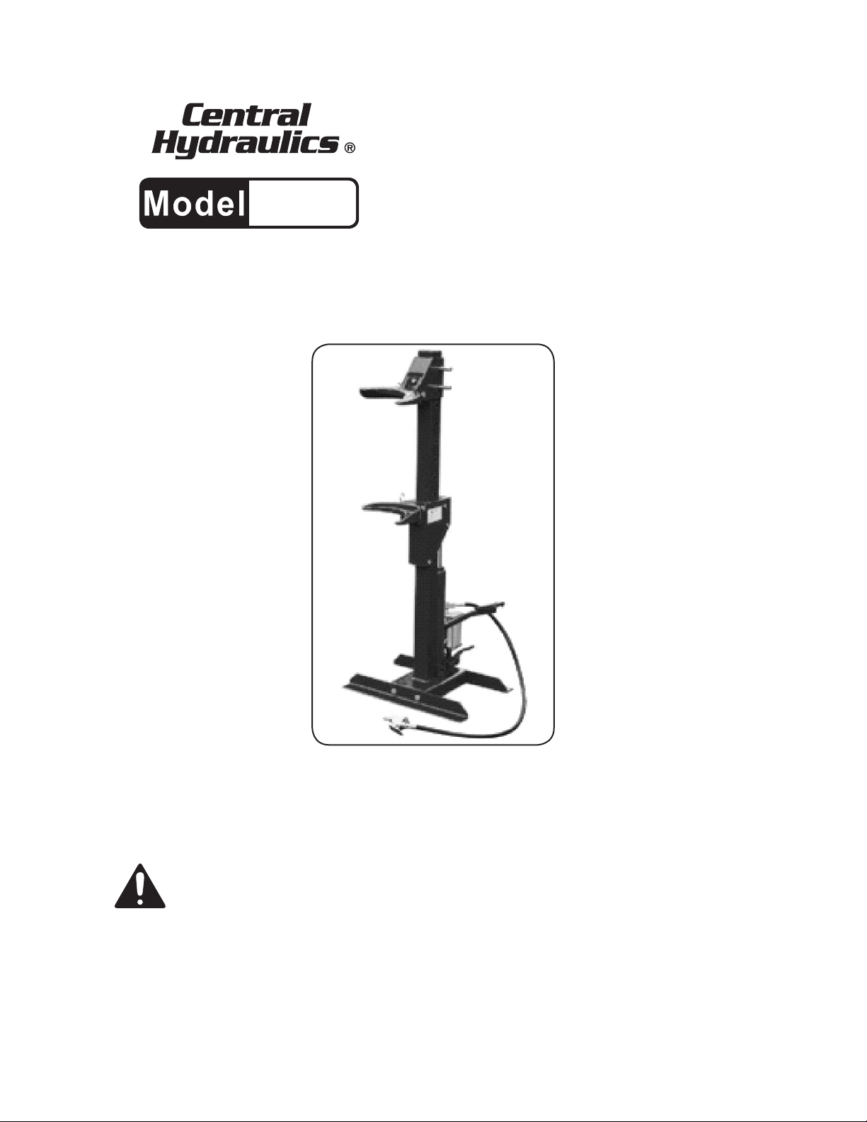
1-TON
AIR/HYDRAULIC
65549
STRUT SPRING
COMPRESSOR
INSTRUCTIONS AND PRECAUTIONS
Distributed exclusively by Harbor Freight Tools®.
3491 Mission Oaks Blvd., Camarillo, CA 93011
Visit our website at: http://www.harborfreight.com
SAVE THESE INSTRUCTIONS. READ ALL
PRECAUTIONS AND INSTRUCTIONS.
Copyright© 2008 by Harbor Freight Tools®. All rights reserved. No portion of this document or any artwork contained
herein may be reproduced in any shape or form without the express written consent of Harbor Freight Tools.
Diagrams within this document may not be drawn proportionally. Due to continuing improvements, actual product
may differ slightly from the product described herein. Tools required for assembly and service may not be included.
For technical questions or replacement parts, please call 1-800-444-3353.
Page 2

CONTENTS
SPECIFICATIONS ........................................................................................3
UNPACKING ................................................................................................3
ASSEMBLY PRECAUTIONS .......................................................................3
IMPORTANT SAFETY INFORMATION .......................................................3
GENERAL SAFETY. ...................................................................................................3
PRE-OPERATIONAL SAFETY. ..................................................................................4
POST OPERATIONAL SAFETY. ................................................................................4
INTRODUCTION ........................................................................................................5
ASSEMBLY.................................................................................................................5
OPERATING INSTRUCTIONS ....................................................................6
MAINTENANCE ..........................................................................................................7
PLEASE READ THE FOLLOWING CAREFULLY .....................................................7
PARTS LIST - SPRING COMPRESSOR .....................................................8
PARTS LIST - AIR MOTOR .........................................................................8
PARTS LIST - HYDRAULIC JACK ..............................................................9
ASSEMBLY DRAWING ─ 1-TON STRUT SPRING COMPRESSOR ....................10
ASSEMBLY DRAWING - AIR MOTOR ..................................................................... 11
ASSEMBLY DRAWING - HYDRAULIC JACK .........................................................12
LIMITED 90 DAY WARRANTY ..................................................................13
SKU 65549 For technical questions, please call 1-800-444-3353. Page 2
Page 3
SPECIFICATIONS
Air Pressure 120 PSI
Maximum Compression 2200 lbs.
Ram Travel 12.8"
Coil Spring Sizes Accepted 4" Dia. to 6.3" Dia.
Spring Length Accepted 5" Long to 18" Long
Shoes
Small Set (4" Springs)
Large Set (6.3" Springs)
UNPACKING
When unpacking, make sure that the item
is intact and undamaged. If any parts are missing
or broken, please call Harbor Freight Tools at the
number shown on the cover of this document as
soon as possible.
ASSEMBLY PRECAUTIONS
Use only according to these instructions. 1.
Improper use can create hazards.
Wear ANSI-approved safety goggles and 2.
heavy-duty work gloves during use.
Keep work area clean and well lit.3.
Keep bystanders out of the area during use.4.
Do not use when tired or when under the 5.
inuence of drugs or medication.
IMPORTANT SAFETY
INFORMATION
In this manual, on the labeling, and all
other information provided with this
product:
This is the safety alert symbol.
It is used to alert you to potential
personal injury hazards. Obey
all safety messages that follow
this symbol to avoid possible
injury or death.
DANGER indicates a
hazardous situation
which, if not avoided,
will result in death or serious injury.
WARNING indicates a
hazardous situation
which, if not avoided,
could result in death or serious
injury.
CAUTION, used with
the safety alert symbol,
indicates a hazardous
situation which, if not avoided,
could result in minor or moderate
injury.
NOTICE is used to
address practices not
related to personal
injury.
CAUTION, without the
safety alert symbol, is
used to address
practices not related to personal
injury.
GENERAL SAFETY.
WARNING!1. Ensure Health & Safety, local
authority, and general workshop practice
regulations are adhered to when using this
equipment.
WARNING!2. Wear approved safety hand and
eye protection (standard spectacles are not
adequate).
WARNING! TRAPPING DANGER3. ─ Keep
hands and ngers away from the spring and
compressing Shoes when in use.
Keep the work area clean, uncluttered and 4.
ensure there is adequate lighting.
Maintain correct balance and footing. Ensure 5.
the oor is not slippery and wear non-slip
shoes.
Remove ill-tting clothes. Remove ties, 6.
watches, rings and other loose jewellery.
Contain and/or tie back long hair.
Wear appropriate protective clothing.7.
Familiarize yourself with the applications, 8.
limitations and potential hazards of the
Spring Compressor.
DO NOT9. force the spring compressor to
achieve a task it was not designed to perform.
DO NOT10. allow untrained persons to use the
spring compressor.
SKU 65549 For technical questions, please call 1-800-444-3353. Page 3
Page 4

PRE-OPERATIONAL SAFETY.
This product is not a toy. Do not allow chil-1.
dren to play with or near this item.
Use for intended purpose(s) only.2.
Inspect before use; do not use if parts are 3.
loose or damaged.
Strut and Spring Compression station should 4.
be securely bolted to the workshop oor
before use.
Apply grease to the front and rear faces of 5.
the main Upright (14) to assist the smooth
sliding of upper and lower strut support (24,
31) Rollers (27).
DO NOT6. operate Spring Compressor if parts
are damaged or missing as this may cause
failure and/or personal injury.
Before compressing, make visual inspec-7.
tion of machine to ensure pins are securely
positioned and that there is no sign of wear
or fatigue. If found, do not use the unit until it
is replaced or repaired by a qualied technician.
Ensure upper and lower Shoes (28, 28A), 8.
Strut Supports (31, 24) and their Retaining
Pins (30, 23, 26) are properly positioned.
Their R-Clips (32) and Circlips (29, 22, 25)
must be properly installed.
Before commencing compression of a spring, 9.
ensure ends of the spring are seated and being held securely in upper and lower Shoes
(28, 28A) of the compressor and cannot slide
out during compression.
Always t the Safety Chain (37) around strut 10.
and spring (see Fig. 2). Ensure Chain is not
trapped in the coils of the spring being compressed.
Maintain product labels and nameplates. 11.
These carry important safety information.
If unreadable or missing, contact Harbor
Freight Tools for a replacement.
When compressing the spring, always stand 12.
to one side of the unit.
DANGER! Stop compressing the spring before the
coils touch. Do not over compress.
Before attempting to remove top cap nut, 13.
always use some type of tool or short stick
to test if the compression has been relieved,
DO NOT use your ngers.
Harbor Freight Tools recommends use of an 14.
appropriate tool, to be supplied by user, to
remove top cap nut from upper strut mount.
Once compressed and strut is removed, it 15.
is a good idea to release the tension on the
spring.
Do not leave the spring under compression a.
in the machine unattended and do not leave
in compression for prolonged periods, i.e.
overnight.
Before releasing the compression, ensure 16.
that the top cap nut is securely fastened according to the manufacturer’s specs.
Release the compression slowly, keeping 17.
your hands and ngers away from the spring
assembly.
Be sure the tension on the spring is fully held 18.
by the strut assembly before removing the
strut from the Shoes (28) of the compressor.
POST OPERATIONAL SAFETY.
When not in use, clean and store the Spring 1.
Compressor in a safe, dry, childproof location.
Maintain the Spring Compressor in good 2.
condition.
Replace or repair damaged parts. Use a.
genuine Harbor Freight Tools parts only.
Unauthorized parts may present a hazard b.
and will invalidate the warranty.
Change Shoes
Two sets of Shoes (28, 28A), one large a.
(28A) and one small (28), are provided.
One set handles springs as small as 4" in
diameter and the larger set handles springs
as large as 6.3" in diameter.
To change to the second pair of Shoes, rst b.
undo and remove the Socket Cap Screw
(33) that secures the Upper to the Upper
Strut Support (31). Remove the R-Clip (32).
Support the Shoe with one hand and slide
the Retaining Pin (23) out.
The Circlip (22) will remain in place on the c.
other end.
Remove the Shoe (28). Hold the alternative d.
Shoe in place within the support bracket and
slide the Retaining Pin (23) back into place
and lock it with the R-Clip (32). Replace
the Socket Cap Screw (33). The Shoes are
SKU 65549 For technical questions, please call 1-800-444-3353. Page 4
Page 5

designed to be used as matched pairs and
should not be mixed.
INTRODUCTION
The 1-Ton Air/Hydraulic Spring Compressor 1.
is an air actuated hydraulic unit with alternative foot operation.
ASSEMBLY
The unit requires minimal assembly before 1.
use.
Attach the Angle Steel (21) to the base of 2.
the Upright (14) by using Bolts (20), Nuts
(18) and Washers (19). Be sure Angle Steel
(21) are xed securely to the base as they
provide stability and will be used to secure
the unit to the oor.
Insert the Foot Pedal (5) into the Socket 3.
(B28) on the hydraulic jack and secure with
the Bolt (10) and Washer (11).
Push Circlips (29) into the groove on each 4.
retaining Pin (30).
Slide the Upper Strut Support (31) over the 5.
Upright (14) to the required height and align
the two holes in the support with two holes
in the Upright. Slide the two Retaining Pins
(30) through the assembly and retain them in
position using the R-clips (32).
Two pairs of shoes (28,28A) are supplied. 6.
Choose one pair of shoes and attach them
to the upper and lower support bracket by
using the socket cap Screw (33), the R-clip
(32), the Retaining Pin (23) and the Circlip
(22). The shoes are designed to be used as
matched pairs and should not be mixed.
The unit must now be xed securely to the 7.
ground in order to ensure the safety of the
user. Mounting holes are to be found in the
brackets, which allow the unit to be secured
by way of masonry bolts or sinking pins (not
included) into concrete.
WARNING! Whichever method is used, ensure the
unit is adequately xed and cannot topple.
WARNING!9. Ensure air supply is clean and
does not exceed 120 PSI.
Too high an air pressure and unclean air will a.
shorten the life of the unit due to excessive
wear, and may be dangerous causing possible damage and/or personal injury.
Drain the air supply tank daily and clean the b.
Air Inlet Filter (A16) weekly.
When used, drain air lter at least once a c.
day.
Fig.1
10. For recommended air source and automatic
oiler hook-up, refer to Fig. 1.
Keep hose away from heat, oil and sharp 11.
edges.
Check hoses for wear and make certain that 12.
all connections are secure.
Read the ENTIRE IMPORTANT
SAFETY INFORMATION section at
the beginning of this document
including all text under
subheadings therein before set up
or use of this product.
AIR SUPPLY SET UP
Ensure the Air Valve (1) is in the “Off” posi-8.
tion before connecting to the air supply. The
Spring Compressor requires 120 PSI to operate at full capacity.
SAVE THESE
INSTRUCTIONS.
SKU 65549 For technical questions, please call 1-800-444-3353. Page 5
Page 6

OPERATING INSTRUCTIONS
Measure the outer diameter of the spring to 1.
be compressed and select the correct set of
Shoes.
Press down on the Release Valve Pedal (6) 2.
releasing air pressure to lower the Under
Strut Support until the Ram is fully retracted
and the Under Strut Support (24) is at its lowest position.
Upper Shoe (9)
Ram
A
Top Cap Nut
Upper
Spring
Seat
Dust
Cover
Lower
Spring
Seat
Under
Strut
Support
Spring
Un-compressed
Strut Housing
Fig. 2
3. The upper Shoe (28) should bear down on
the rst full coil down from the top of the
strut. The lower Shoe should be pushing up
on the rst full coil up from the bottom of the
strut. (See Fig. 2.)
Measure the distance between these coils a.
and adjust the position of the upper strut
support so that the distance between the
Shoes is slightly larger than required.
Ensure that the Retaining Pins (30) hold-b.
ing the Upper Strut Support (31) are fully
inserted and secured with the R-Clip (32)
and Circlips (29) provided.
Use the Foot Pedal (5) to raise the Under c.
Strut Support (24) to nely adjust the distance between the Shoes.
Before compressing, make a visual inspec-4.
tion of the tool to ensure all Retaining Pins
are securely positioned and that there is no
sign of wear or metal fatigue.
Upper Strut Mount
Spring
Compressed
Lower Strut
B
Mount
If wear or fatigue is found, do not use the a.
Tool. Have the tool replaced or repaired by
a qualied technician.
Fit the strut into the Shoes (28) and ensure 5.
that the lower coil used lies behind the inner
retaining rim at the back of the Shoe (28).
Operate the Foot Pedal (5) to raise the upper
coil end into contact with the upper spring
seat, ensuring the coil at both ends are securely retained by the raised inner and outer
rims within the Shoes (28, 28A).
Wrap one Safety Chain (37) around the por-6.
tion of the spring and strut protruding from
the upper Shoe (28) ensuring that the Chain
lies above the Shoe. (See Fig. 2.)
Wrap the other Safety Chain around the 7.
spring and strut protruding from the lower
Shoe ensuring that the Chain lies below the
Shoe.
Fasten each Chain behind the Upright (14) a.
using the attached spring catches. Make
sure each Chain is as tight as possible.
Do not position the Chain in the coils held
between the Shoes (28, 28A).
When applying compression to the spring, 8.
always stand to one side of the unit.
Gradually compress the spring by pumping 9.
the Foot Pedal (5) or operating the Air Valve
(1) ensuring that the spring and strut remain
securely held at all times.
Ensure that the strut and the Upright (14) of 10.
the compressor are correctly aligned at all
times during spring compression.
For conical springs, the center line of the a.
spring should remain parallel to the compressor body.
DANGER! Stop compressing the spring before the
coil windings touch. You need only compress
the spring until the upper spring seat is free
from spring pressure.
Before attempting to remove top cap nut on 11.
the strut, use a tool or short stick to test if the
spring compression has been relieved from
the upper spring seat. Do not use your hands
or ngers.
Harbor Freight Tools recommends the use of 12.
properly designed strut tools to remove the
top cap nut from the shock absorber piston.
SKU 65549 For technical questions, please call 1-800-444-3353. Page 6
Page 7

Ensure that the shock absorber is supported a.
as the top cap nut is removed to prevent it
falling down through the coils and causing
injury.
Once compressed and the strut removed, it 13.
is recommended to release the tension on
the spring.
Do not leave the spring under compression a.
unattended and do not leave in compression for prolonged periods. I.e. overnight.
Allow the spring to gradually decompress by 14.
carefully pressing the Valve Release Pedal
(6) keeping your hands and ngers away
from the spring assembly.
Replace the spring or shock absorber as 15.
necessary and reassemble the strut by rst
compressing the spring and then introducing the shock absorber up through the lower
Shoe (28) and compressed spring coils.
Re-position the upper strut mount and se-a.
cure with the top cap nut.
Before releasing the compression, ensure 16.
that the top cap nut is securely tightened according to the manufacturer’s specs.
Release the compression slowly keeping 17.
your hands and ngers away from the spring
assembly.
Be sure that the spring ends are rmly and 18.
securely seated in the upper and lower
Shoes of the Compressor before removing
the strut from the Spring Compressor.
serious damage to the jack and invalidate the
warranty!
Bleeding the Hydraulic System
The Strut Spring Compressor must be se-3.
curely mounted on a at and level surface.
Wipe the Oil Filler Plug (38) and its surround-4.
ing area at the side of the Ram (7).
With the tip of a at tip screwdriver, pry and 5.
remove the rubber Oil Filler Plug.
Pour fresh hydraulic jack oil into the Ram (7) 6.
until it starts to overow.
Step on the Valve Release Pedal (6) and 7.
allow the Under Strut Support (24) to be
lowered completely.
While holding the Valve Release Pedal (6) 8.
down, rapidly pump the Foot Pedal (5) at
least ve full strokes. This should purge the
air out of the system.
Repeat step 6 above to make sure that the 9.
Ram (7) is lled with oil.
Wipe the plug and place its edge against 10.
the ll-hole and while applying thumb force
behind the plug, work the rubber plug back
into the ll-hole with the aid of the at tipped
screwdriver.
After the plug is inserted, wipe off spilled oil 11.
from jack exterior with a clean and dry rag.
CAUTION: DO NOT operate the jack when the Oil
Filler Plug (38) is removed.
MAINTENANCE
Before each use, check the compressor to 1.
ensure it is not damaged or worn. If in any
doubt DO NOT use the tool.
Remove it from service immediately and a.
have it replaced or repaired by a qualied
technician.
Relling the hydraulic system with oil is rarely 2.
necessary but the oil level should be checked
in the event of a loss of performance.
To check oil level, ensure the Under Strut a.
Support (24) is fully lowered, remove ller
plug and check that level is within .4" of ller
hole. Add hydraulic jack oil if necessary.
WARNING: DO NOT use brake uid, or any uid
PLEASE READ THE FOLLOWING
CAREFULLY
THE MANUFACTURER AND/OR DISTRIBUTOR HAS
PROVIDED THE PARTS LIST AND ASSEMBLY DIAGRAM
IN THIS DOCUMENT AS A REFERENCE TOOL ONLY.
NEITHER THE MANUFACTURER OR DISTRIBUTOR
MAKES ANY REPRESENTATION OR WARRANTY OF ANY
KIND TO THE BUYER THAT HE OR SHE IS QUALIFIED
TO MAKE ANY REPAIRS TO THE PRODUCT, OR THAT
HE OR SHE IS QUALIFIED TO REPLACE ANY PARTS OF
THE PRODUCT. IN FACT, THE MANUFACTURER AND/OR
DISTRIBUTOR EXPRESSLY STATES THAT ALL REPAIRS
AND PARTS REPLACEMENTS SHOULD BE UNDERTAKEN
BY CERTIFIED AND LICENSED TECHNICIANS, AND NOT
BY THE BUYER. THE BUYER ASSUMES ALL RISK AND
LIABILITY ARISING OUT OF HIS OR HER REPAIRS TO THE
ORIGINAL PRODUCT OR REPLACEMENT PARTS THERETO,
OR ARISING OUT OF HIS OR HER INSTALLATION OF
REPLACEMENT PARTS THERETO.
other than hydraulic jack oil as this will cause
SKU 65549 For technical questions, please call 1-800-444-3353. Page 7
Page 8

PARTS LIST - SPRING
COMPRESSOR
Part Description Qty.
1 Air Valve 1
2 Air Hose 1
3 Air Motor 1
4 Washer 1
5 Foot Pedal 1
6 Valve Release Pedal 1
7 Ram 1
8 Pin 1
9 Ram 1
10 Bolt 1
11 Washer 1
12 Screw 1
13 T-Connector 1
14 Upright 1
15 Washer 2
16 Lock Washer 2
17 Bolt 2
18 Nut 4
19 Washer 4
20 Bolt 4
21 Angle Steel 2
22 Circlip 2
23 Retaining Pin 2
24 Under Strut Support 1
25 Circlip 6
26 Retaining Pin 3
27 Roller 2
28 Shoe - Small 4" 2
28A Shoe - Large 6.3" 2
29 Circlip 2
30 Retaining Pin 2
31 Upper Strut Support 1
32 R-Clip 4
33 Socket Cap Screw 1
34 Safety Ring 1
35 Bolt 2
36 Washer 2
37 Safety Chain 2
38 Oil Filler Plug (Hidden) 1
PARTS LIST - AIR MOTOR
Part Description Qty.
A01 Air Pump Cylinder 1
A02 Nut 1
A03 Sealing Ring 1
A04 Nylon Ring 1
A05 Copper Ring 1
A06 Air Cylinder Seat 1
A07 Nut 1
A08 Spring 1
A09 Air Pump Piston 1
A10 O-Ring 2
A11 Big Piston 1
A12 Air Cylinder 1
A13 Screw 2
A14 Lock Washer 2
A15 Safety Cover 1
A16 Filter 1
A17 Silencing Pad 1
A18 Small Piston 1
A19 O-Ring 1
A20 O-Ring 1
A21 Sealing Ring 1
A22 Bolt 3
A23 Nylon Ring 1
A24 O-Ring 2
A25 O-Ring 1
A26 Air Cylinder Cap 1
A27 Bolt 4
A28 Coupler Seat 1
A29 Retaining Ring 1
A30 O-ring 2
A31 Coupler 1
A32 Air Hose 1
A33 Lock Lever 1
A34 Lever 1
A35 Nut 1
A36 O-ring 1
A37 O-ring 1
A38 Packing 1
A39 Throttle 1
A40 Spring 1
A41 Lock Nut 1
A42 Bolt 1
A43 Valve Body 1
A44 Screw 1
A45 Screen 1
A46 O-Ring 1
A47 Quick Coupler-Male 1
A48 Coupler Seat 1
SKU 65549 For technical questions, please call 1-800-444-3353. Page 8
Page 9

PARTS LIST - HYDRAULIC JACK
Part Description Qty.
B1 Screw Protector 1
B2 Screw 1
B3 O-ring 1
B4 Screw 1
B5 Spring 1
B6 Ballcap 1
B7 Ball 1
B8 Base 1
B9 Pin 3
B10 Release Pedal 1
B11 R-pin 4
B12 Screw 1
B13 O-ring 1
B14 Screw 1
B15 Rubber Pad 1
B16 Ballcap 1
B17 Spring 1
B18 Ball 6
B19 Copper Washer 2
B20 Piston Housing 1
B21 O-ring 1
B22 Nylon Ring 1
B23 Dust Seal 1
B24 Small Piston 1
B25 Pin 1
B27 Link 1
B28 Socket 1
B29 Washer 1
B30 Cylinder 1
B31 Pump Pedal 1
B32 Washer 1
B33 Screw 1
B34 Oil Plug 1
B35 Recervoir 1
B36 Spring 2
B37 Copper Washer 2
B38 Screw 2
B39 O-ring 1
B40 Nylon Ring 1
B41 Circlip 1
B42 Ram 1
B43 O-ring 1
B44 Nylon Ring 1
B45 Cylinder Cap 1
SKU 65549 For technical questions, please call 1-800-444-3353. Page 9
Page 10

1
2
3
4
10
11
5
6
9
14
15
16
17
18
19
20
21
8
7
22
23
27
26
25
24
28
34
35
36
37
33
32
31
29
30
13
12
38
23
Assembly Drawing ─ 1-Ton Strut Spring Compressor
SKU 65549 For technical questions, please call 1-800-444-3353. Page 10
Page 11

Assembly Drawing - Air Motor
SKU 65549 For technical questions, please call 1-800-444-3353. Page 11
Page 12

Assembly Drawing - Hydraulic Jack
SKU 65549 For technical questions, please call 1-800-444-3353. Page 12
Page 13

LIMITED 90 DAY WARRANTY
Harbor Freight Tools Co. makes every effort to assure that its products meet high quality and durability standards, and warrants to the original purchaser that this product is free from defects in materials
and workmanship for the period of 90 days from the date of purchase. This warranty does not apply to
damage due directly or indirectly, to misuse, abuse, negligence or accidents, repairs or alterations outside
our facilities, criminal activity, improper installation, normal wear and tear, or to lack of maintenance. We
shall in no event be liable for death, injuries to persons or property, or for incidental, contingent, special
or consequential damages arising from the use of our product. Some states do not allow the exclusion or
limitation of incidental or consequential damages, so the above limitation of exclusion may not apply to
you. THIS WARRANTY IS EXPRESSLY IN LIEU OF ALL OTHER WARRANTIES, EXPRESS OR IMPLIED, INCLUDING THE WARRANTIES OF MERCHANTABILITY AND FITNESS.
To take advantage of this warranty, the product or part must be returned to us with transportation
charges prepaid. Proof of purchase date and an explanation of the complaint must accompany the mer-
chandise. If our inspection veries the defect, we will either repair or replace the product at our election
or we may elect to refund the purchase price if we cannot readily and quickly provide you with a replacement. We will return repaired products at our expense, but if we determine there is no defect, or that the
defect resulted from causes not within the scope of our warranty, then you must bear the cost of returning
the product.
This warranty gives you specic legal rights and you may also have other rights which vary from
state to state.
3491 Mission Oaks Blvd. • PO Box 6009 • Camarillo, CA 93011 • (800) 444-3353
Record Serial Number Here:
Note: If product has no serial number, record month and year of purchase instead.
Note: Some parts are listed and shown for illustration purposes only, and are not available individually as
replacement parts.
SKU 65549 For technical questions, please call 1-800-444-3353. Page 13
 Loading...