

Harbor Freight Tools 65162 Owner's Manual
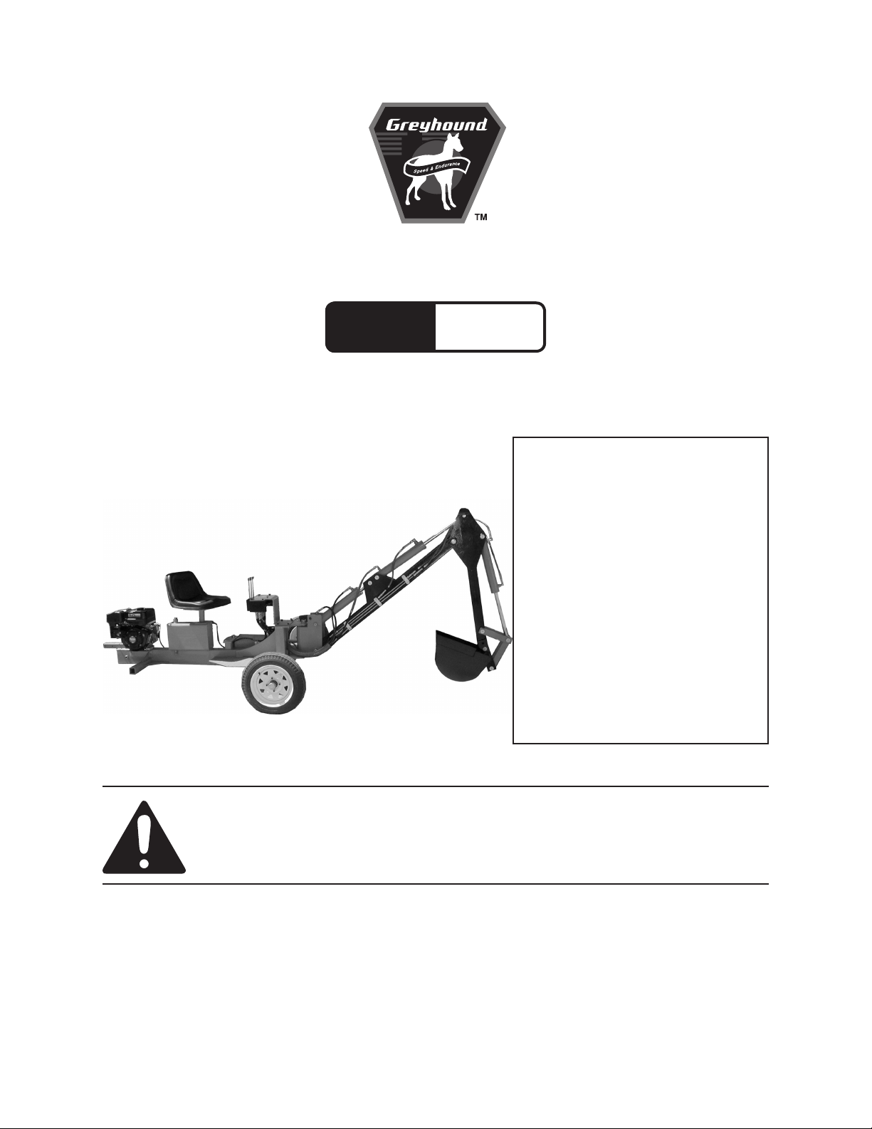
9 HP RIDE-ON TRENCHER
Model
65162
SET UP, OPERATING, AND SERVICING
INSTRUCTIONS
WARNING!
IMPORTANT INFORMATION
The Hitch Coupler MUST be properly
secured to the hitch ball of the towing vehicle.
After assembly and attachment, pull up and
down on the Hitch Coupler to make sure the
hitch ball is tting snugly in the Hitch Coupler.
There must be no play between the hitch
ball and Hitch Coupler. If there is play, tighten
the Adjustment Nut until no play is present. If
the Adjustment Nut is too tight, the Handle
will not lock. Carefully read and follow
the complete instructions in this manual
BEFORE setup or use.
If the Coupler is not secured
properly, the ball could come loose
while the Log Splitter is in motion,
possibly causing property damage,
SERIOUS PERSONAL INJURY, or
DEATH.
Revised 11a
Visit our website at: http://www.harborfreight.com
Read this material before using this product.
Failure to do so can result in serious injury.
SAVE THIS MANUAL.
Copyright© 2008 by Harbor Freight Tools®. All rights reserved. No portion of this
manual or any artwork contained herein may be reproduced in any shape or form
without the express written consent of Harbor Freight Tools. Diagrams within this
manual may not be drawn proportionally. Due to continuing improvements, actual
product may differ slightly from the product described herein. Tools required for
assembly and service may not be included.
For technical questions or replacement parts, please call 1-800-444-3353.

CONTENTS
IMPORTANT SAFETY
INFORMATION ............................ 4
SET UP PRECAUTIONS .................... 4
OPERATING PRECAUTIONS ............ 5
SERVICE PRECAUTIONS ............. 6
REFUELING: .................................7
TRENCHER PRECAUTIONS ........ 7
BASIC SPECIFICATIONS ............. 8
CLEANING, MAINTENANCE, AND
LUBRICATION SCHEDULE .......... 21
AFTER 20 OPERATION HOUR
BREAK-IN PERIOD: ................21
AFTER EVERY 25 OPERATION
HOURS: ....................................21
AFTER EVERY 50 OPERATION
HOURS: ....................................21
AFTER EVERY 100
OPERATION HOURS: ..............21
AFTER EVERY 300
OPERATION HOURS: ..............21
PERIODICALLY: .........................21
UNPACKING .................................. 8
SET UP INSTRUCTIONS ............... 8
ASSEMBLY.........................................8
ATTACHING THE LEG ASSEMBLY 10
PURGING THE CYLINDER ..............12
OPERATING INSTRUCTIONS .... 12
STARTING THE ENGINE .................12
CHECKING ENGINE OIL LEVEL 12
ENGINE DIAGRAM ...................... 13
CHECKING FUEL LEVEL ........... 14
BREAK-IN PERIOD ....................14
EQUIPMENT OPERATION ...............15
MOVING THE TRENCHER ......... 16
TRANSPORTING THE
TRENCHER ..............................17
TECHNICAL SPECIFICATIONS .. 19
SERVICING .................................. 19
MAINTENANCE PROCEDURES .....19
ENGINE OIL CHANGE ...............19
AIR FILTER ELEMENT
MAINTENANCE .......................19
SPARK PLUG MAINTENANCE .. 20
FUEL FILTER REPLACEMENT
(IF EQUIPPED) .........................20
STORAGE ........................................21
LUBRICATION POINTS ...................22
TROUBLESHOOTING ...................... 23
PARTS LIST ................................. 25
GENERAL ASSEMBLY
DIAGRAM .................................. 26
CYLINDER HEAD PARTS LIST
& DIAGRAM .............................. 27
CRANK CASE PARTS LIST &
DIAGRAM .................................. 28
CRANK CASE COVER PARTS
LIST AND DIAGRAM ................. 29
CRANKSHAFT/PISTON PARTS
LIST & DIAGRAM ...................... 30
GAS DISTRIBUTION
ADJUSTMENT SYSTEM
PARTS LIST & DIAGRAM ......... 31
STARTER SUBASSEMBLY
PARTS LIST & DIAGRAM ......... 32
DIVERSION ASSEMBLY PARTS
LIST & DIAGRAM ...................... 33
Page 2SKU 65162 For technical questions, please call 1-800-444-3353.

CARBURETOR PARTS LIST &
DIAGRAM .................................. 34
FLYWHEEL/COIL ASSEMBLY
PARTS LIST & DIAGRAM ......... 35
CONTROL SYSTEM PARTS
LIST & DIAGRAM ...................... 36
AIR CLEANER PARTS LIST &
DIAGRAM .................................. 37
MUFFLER PARTS LIST &
DIAGRAM .................................. 38
FUEL TANK PARTS LIST &
DIAGRAM .................................. 39
LIMITED 1 YEAR / 90 DAY
WARRANTY .............................. 40
EMISSION CONTROL SYSTEM
WARRANTY .............................. 40
Page 3SKU 65162 For technical questions, please call 1-800-444-3353.

SAVE THIS MANUAL
Keep thi s man ual for th e safety
warnings and prec autions , asse mbly,
operating, inspection, maintenance and
cleaning procedures. Write the product’s
serial number in the back of the manual near
the assembly diagram (or month and year of
purchase if product has no number). Keep
this manual and the receipt in a safe and dry
place for future reference.
IMPORTANT SAFETY
INFORMATION
In this manual, on the labeling,
and all other information
provided with this product:
This is the safety alert
symbol. It is used to alert
you to potential personal
injury hazards. Obey all
safety messages that
follow this symbol to avoid
possible injury or death.
DANGER indicates
DANGER
situation which, if not
avoided, will result in death or
serious injury.
WARNING
WARNING
hazardous situation which, if
not avoided, could result in
death or serious injury.
CAUTION, used
CAUTION
alert symbol, indicates a
hazardous situation which, if
not avoided, could result in
minor or moderate injury.
a hazardous
indicates a
with the safety
Notice
CAUTION
NOTICE is used to
address practices
not related to personal injury.
CAUTION, without
the safety alert
symbol, is used to address
practices not related to
personal injury.
WARNING! Read all instructions.
Failure to follow all instructions
listed below may result in re,
serious injury and/or DEATH.
The warnings and precautions
discussed in this manual cannot
cover all possible conditions and
situations that may occur. It must
be understood by the operator that
common sense and caution are
factors which cannot be built into
this product, but must be supplied
by the operator.
SAVE THESE INSTRUCTIONS
SET UP PRECAUTIONS
Gasoline fuel and fumes are 1.
ammable, and potentially explosive.
Use proper fuel storage and handling
procedures. Do not store fuel or
other ammable materials nearby.
Have multiple ABC class re 2.
extinguishers nearby.
This equipment has a spark 3.
arresting mufer included. A spark
arresting mufer is required by law
in California, on some US Forest
Service land, and possibly in other
areas or situations.
Set up and use only on a at, level, 4.
well-ventilated surface.
Page 4SKU 65162 For technical questions, please call 1-800-444-3353.

Wear ANSI-approved safety goggles, 5.
heavy-duty work gloves, and dust
mask/respirator during set up and
use.
Use only oil and fuel recommended 6.
in the “Specications” section of this
manual.
OPERATING PRECAUTIONS
1. CARBON MONOXIDE
HAZARD
Using an engine indoors
CAN KILL YOU IN
MINUTES.
Engine exhaust contains carbon
monoxide. This is a poison you
cannot see or smell.
NEVER use inside a home or garage,
EVEN IF doors and windows are
open.
Only use OUTSIDE and far away
from windows, doors, and vents.
Keep children and observers 20 feet 2.
away from the equipment while it is
operating.
Tools for your model. Accessories
that may be suitable for one piece of
equipment may become hazardous
when used on another piece of
equipment.
Stay alert, watch what you are 7.
doing and use common sense when
operating a piece of equipment. Do
not use a piece of equipment while
tired or under the inuence of drugs,
alcohol or medication.
Do not overreach. Keep proper 8.
balance at all times. This enables
better control of the equipment in
unexpected situations.
Dress properly. Do not wear loose 9.
clothing or jewelry. Keep hair,
clothing and gloves away from
moving parts. Loose clothes, jewelry
or long hair can be caught in moving
parts.
Parts of the equipment, especially 10.
exhaust system components, get
very hot during use. Stay clear of hot
parts.
Do not leave the equipment 3.
unattended when it is running. Turn
off the equipment (and remove safety
keys, if available) before leaving the
work area.
Wear ANSI-approved safety goggles 4.
and hearing protection during use.
People with pacemakers should 5.
consult their physician(s) before
use. Electromagnetic elds in close
proximity to a heart pacemaker could
cause pacemaker interference
or pacemaker failure. Caution is
necessary when near the engine’s
magneto or recoil starter.
Use only accessories that are 6.
recommended by Harbor Freight
Do not cover the engine or equipment 11.
during operation.
Keep the equipment, engine, and 12.
surrounding area clean at all times.
Use the equipment, accessories, etc., 13.
in accordance with these instructions
and in the manner intended for the
particular type of equipment, taking
into account the working conditions
and the work to be performed. Use
of the equipment for operations
different from those intended could
result in a hazardous situation.
Do not operate the equipment with 14.
known leaks in the engine’s fuel system.
Page 5SKU 65162 For technical questions, please call 1-800-444-3353.

This product contains or, when 15.
used, produces a chemical known
to the State of California to cause
cancer and birth defects or other
reproductive harm. (California Health
& Safety Code § 25249.5, et seq.)
When spills of fuel or oil occur, they 16.
must be cleaned up immediately.
Dispose of uids and cleaning
materials as per any local, state,
or federal codes and regulations.
Store oil rags in a bottom-ventilated,
covered, metal container.
Keep hands and feet away from 17.
moving parts. Do not reach over or
across equipment while operating.
Before use, check for misalignment 18.
or binding of moving parts, breakage
of parts, and any other condition
that may affect the equipment’s
operation. If damaged, have the
equipment serviced before use.
Many accidents are caused by poorly
maintained equipment.
Use the correct equipment for the 19.
application. Do not modify the
equipment and do not use the
equipment for a purpose for which it
is not intended.
SERVICE PRECAUTIONS
Before service, maintenance, or 1.
cleaning:
Turn the engine switch to its a.
“OFF” position.
Allow the engine to completely cool.b.
Then, remove the spark plug c.
wire(s) from the spark plug(s).
guards include mufer, air cleaner,
mechanical guards, and heat shields,
among other guards.
Do not alter or adjust any part of 3.
the equipment or its engine that
is sealed by the manufacturer
or distributor. Only a qualied
service technician may adjust
parts that may increase or
decrease governed engine speed.
Wear ANSI-approved safety goggles, 4.
heavy-duty work gloves, steel toe
work boots, dust mask/respirator and
hard hat during use and service.
Do not allow the hydraulic hose to 5.
come in contact with any hot part
of the unit. The hose might be
damaged, possibly causing it to burst
or leak under high pressure.
Maintain labels and nameplates 6.
on the equipment. These carry
important information. If unreadable
or missing, contact Harbor Freight
Tools for a replacement.
Have the equipment serviced by a 7.
qualied repair person using only
identical replacement parts. This
will ensure that the safety of the
equipment is maintained. Do not
attempt any service or maintenance
procedures not explained in this
manual or any procedures that you
are uncertain about your ability to
perform safely or correctly.
Store equipment out of the reach of 8.
children.
Follow scheduled engine and 9.
equipment maintenance.
Keep all safety guards in place and 2.
in proper working order. Safety
Page 6SKU 65162 For technical questions, please call 1-800-444-3353.

Refueling:
Do not smoke, or allow sparks, 1.
ames, or other sources of ignition
around the equipment, especially
when refuelling.
Do not rell the fuel tank while the 2.
engine is running or hot.
do this type of work. To reduce your
exposure to these chemicals: work in
a well ventilated area, and work with
approved safety equipment, such as
those dust masks that are specially
designed to lter out microscopic
particles. (California Health & Safety
Code § 25249.5, et seq.)
Do not ll fuel tank to the top. Leave 3.
a little room for the fuel to expand as
needed.
Refuel in a well-ventilated area only.4.
TRENCHER PRECAUTIONS
Always make sure the hitch coupler 1.
is securely xed to the vehicle before
moving it. If the Coupler is not secured properly, the link could come
loose while the trailer is in motion,
possibly causing property damage,
SERIOUS PERSONAL INJURY, or
DEATH.
Contact local utility companies 2.
before beginning any project. Buried
utility lines may not be marked
and, if struck, can cause SERIOUS
PERSONAL INJURY or DEATH.
Never place your hands or body near 4.
a hydraulic uid leak. High-pressure
uid can be forced under the skin
resulting in serious injury.
Do not exceed 30 MPH when towing 5.
the Trencher.
Do not tow the Trencher on roads or 6.
highways. This product is not D.O.T.
compliant, and is not road legal.
SAVE THESE
INSTRUCTIONS.
WARNING: Some dust created by 3.
power sanding, sawing, grinding,
drilling, and other construction
activities, contains chemicals
known [to the State of California] to
cause cancer, birth defects or other
reproductive harm. Some examples
of these chemicals are:
• Lead from lead-based paints
• Crystalline silica from bricks and
cement or other masonry products
• Arsenic and chromium from
chemically treated lumber
Your risk from these exposures
varies, depending on how often you
Page 7SKU 65162 For technical questions, please call 1-800-444-3353.
BASIC SPECIFICATIONS
Fuel
Type
Capacity 1.58 Gallons
Type SAE
Engine Oil
Capacity 1.2 Quarts
Hydraulic Oil 3.5 Gallons
Engine Speed 3,600 RPM
Engine Family 6CGP.2702GA
Tire Ination 65 PSI
Digging Depth 5-1/2 and 7 Feet Deep
Maximum Digging
Reach
Spool Valve Rated 10.6 G.P.M.
Pump Rated 2.7 G.P.M.
Boom Travel 60° Left/Right
Bucket Load Capacity 1.24 Cubic Feet
Hitch Ball size 1-7/8” Diameter
Note: Additional specications found
in the TECHNICAL ENGINE
SPECIFICATIONS chart in this
manual.
The emission control system for this
product’s Engine is warranted for standards
set by the U.S. Environmental Protection
Agency and by the California Air Resources
Board (also known as CARB). For warranty
information, refer to the last pages of this
manual.
At high altitudes, the engine’s carburetor,
governor (if so equipped), and any other
parts that control the fuel-air ratio will need to
be adjusted by a qualied mechanic to allow
efcient high-altitude use and to prevent
damage to the engine and any other devices
used with this product.
86+ octane unleaded
gasoline
10W 30 above 32° F
5W30 at 32° F or below
8 Feet
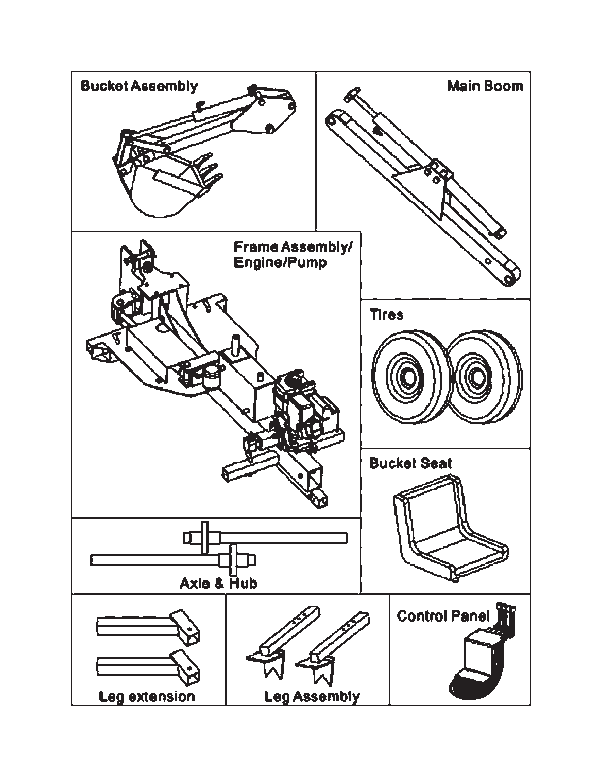
UNPACKING
When unpacking, check to make sure
that the item is intact and undamaged. If
any parts are missing or broken, please call
Harbor Freight Tools at the number shown
on the cover of this manual as soon as
possible.
SET UP INSTRUCTIONS
Read the ENTIRE IMPORTANT
SAFETY INFORMATION
section at the beginning of this
manual including all text under
subheadings therein before set
up or use of this product.
WARNING
Note: For additional information regarding
Risk of accidental
starting; resulting
in serious personal injury.
Turn the Power Switch of the
equipment to its “OFF”
position, wait for the engine to
cool, and unplug the spark
plug wire(s) before
assembling or making any
adjustments to the equipment.
the parts listed in the following pages,
refer to the Assembly Diagram near
the end of this manual.
Assembly
This equipment has a spark arresting 1.
mufer. A spark arresting mufer is
required by law in California, on some
US Forest Service land, and possibly
in other areas or situations.
Due to the size of the Trencher and 2.
its components, assistance may be
required during the entire assembly
process.
Use jacks (not included) to evenly 3.
raise the Frame Assembly (90)
& support with jack stands (not
included).
REV 09b, 09i
Page 8SKU 65162 For technical questions, please call 1-800-444-3353.
Page 9SKU 65162 For technical questions, please call 1-800-444-3353.
Mount both Axles (50) near the boom 4.
end of the frame and secure with
Lock Pins (82).
Boom
Pivot (38)
Clevis Pin
No. 1 (29)
Place a Tire (52) over the four studs 5.
on each Hub. Secure the Tires to
the Hubs, using four Lug Nuts (53)
per Tire. The lug nuts must be snug.
Inate the tires to 65 PSI.
Slightly raise the Jacks, remove the 6.
Jack Stands, then lower the Jacks.
Block the tires and tighten the Lug
Nuts to at least 90 Ft-Lbs.
Attach Seat (73) to the Seat Bottom 7.
Plate (10) and secure both Seat and
Plate to the post on top of Hydraulic
Oil Tank.
Attach the Control Support (3) to the 8.
Frame Assembly (90) using four Hex
Bolts (81).
NOTE: The Hydraulics of this unit are
tested before shipment. There
may be hydraulic uid present in
components. Assemble the unit in
an area that will not be damaged
by leaking hydraulic uid. It is
recommended that you wrap
rags securely over the Hydraulic
connectors on all the Cylinders during
assembly. Wear splash-resistant
ANSI approved safety goggles and
other protective gear to prevent injury
from leaking uid.
Attach the Main Boom (36) to the 9.
Boom Pivot (38) using the Pin (42)
through the bottom hole and Clevis
Pin No. 1 (29) through the upper
hole. Secure both pins with Hair Pin
Clip (31); Pin (42) requires one Cotter
pin on each end. See photo above
right.
Main
Boom
(36)
Pin
(42)
Mount the Boom Extension (34) to 10.
the Main Boom (36) using the Pin
(42), left, and Clevis Pin No. 1 (29),
top. Secure both pins with Hair Pin
Clip (31).
Attach the Hitch Coupler (58) to 11.
the Frame Assembly (90) under the
Engine (74) using Hex Bolts (75) and
Hex HD. Bolt (72).
Connect, tighten, and check all 12.
hydraulic hose ttings to the proper
connections, as shown in the Hose
Connection Diagram. Hoses and
ttings are numbered. Tighten all
ttings.
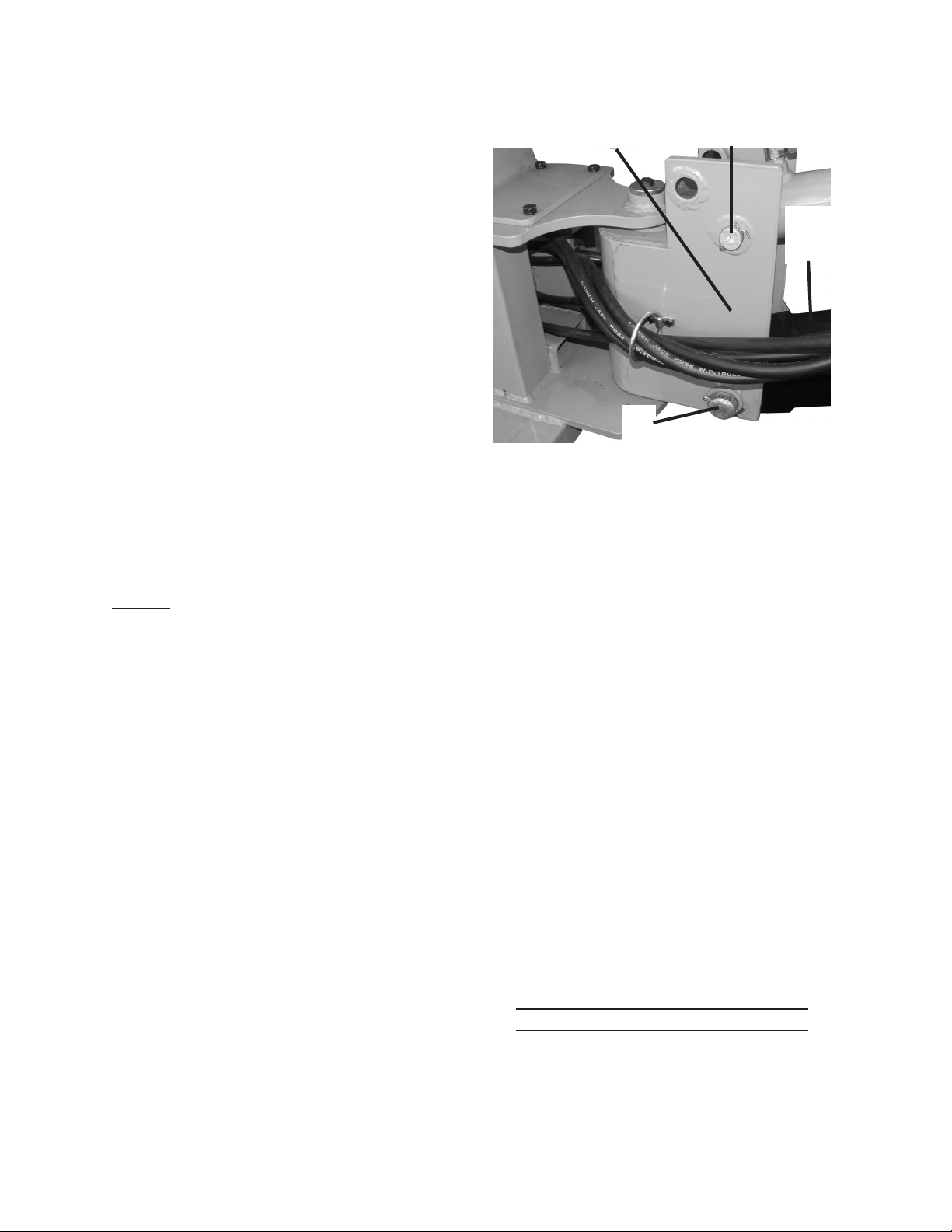
Open the Hydraulic Fluid Fill Plug 13.
(11). Top off the Hydraulic Fluid
Reservoir with high quality hydraulic
uid. Check that the Fluid level is
between the lines on the attached
Dipstick. Close the Hydraulic Fluid Fill
Plug securely.
Attaching the Leg Assembly
To use the Trencher, the Leg 1.
Assemblies must be installed next to
the Boom (36), and the Wheels and
Axles (50) moved to the rear.
REV 09i
Page 10SKU 65162 For technical questions, please call 1-800-444-3353.
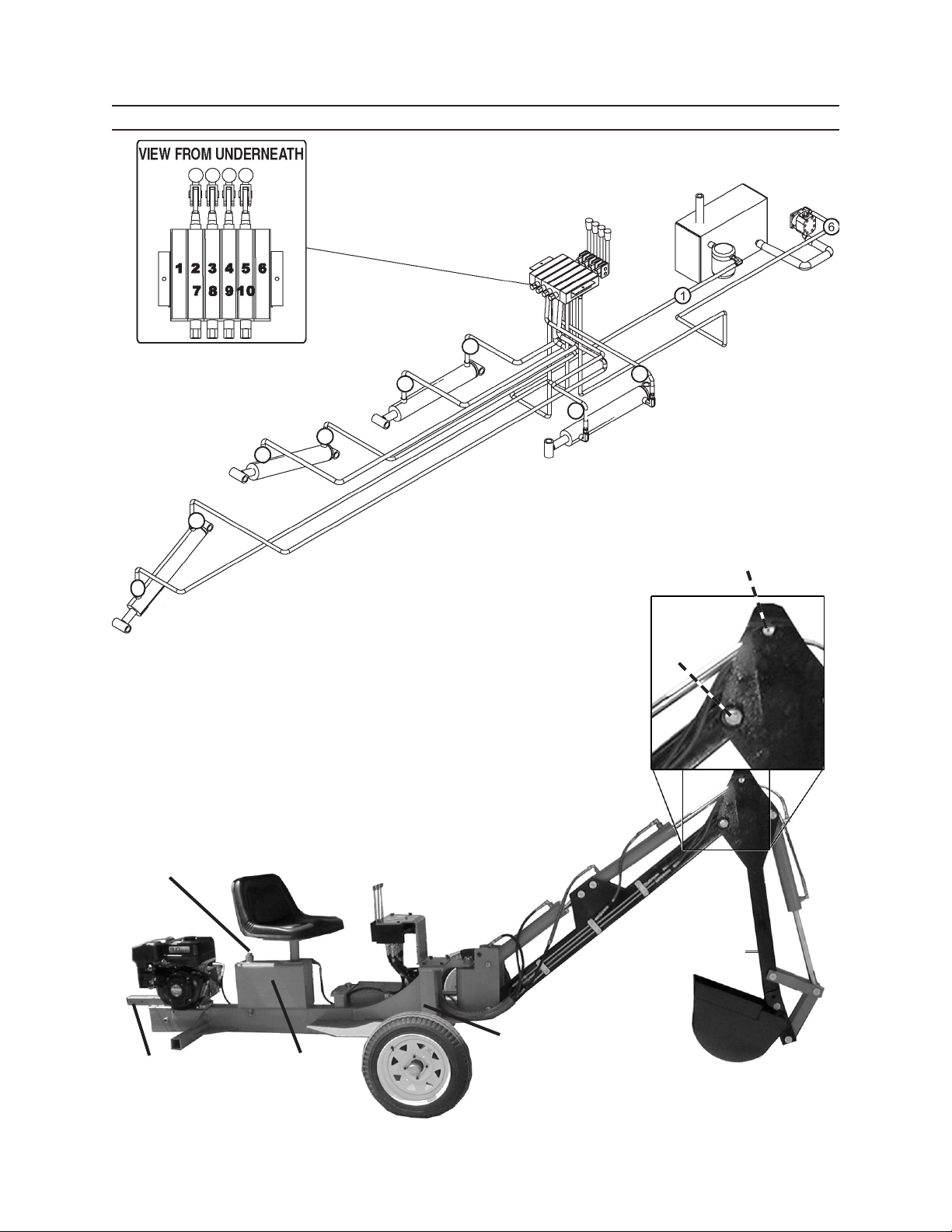
Hose Connection Diagram
Control Panel / Spool Valve (9)
Hydraulic Fluid
Reservoir
part of Frame (90)
Hydraulic
Pump (65)
Bucket
Control
Cylinder
7
2
Boom
Extension
Cylinder
8
3
Main Boom
Cylinder
9
4
5
10
Boom Swing
Cylinder
Clevis Pin No. 1
(29)
Pin
(42)
Hydraulic Fluid
Fill Plug (11)
Engine (74)
Mount Hitch
Coupler (58)
Here
Seat (73)
Hydraulic
Fluid
Reservoir
Control
Panel
(9)
Boom Extension (34)
Frame Assy. (90)
TOW CONFIGURATION
REV 09b, 11a
Page 11SKU 65162 For technical questions, please call 1-800-444-3353.
Move the Trencher to the work area 2.
(See “Starting The Engine” - page
14).
Start the engine and use the Boom 3.
Controls to curl the bucket toward the
boom without touching the ground.
Moving the Bucket As sembly (32)
down to the ground will raise the
Frame Assembly (90). Lift the Tires
just off the ground and stop.
Ensure the controls will not be 4.
touched or bumped, and that the
Trencher will remain motionless.
Never place any part of your body
under the trencher.
With the Tires (52) off the ground, 5.
remove the Wheel and Axle (50)
to the operator’s left and replace
with the left side Extension Leg (19)
and Leg Assembly (24). Direct the
Extension Leg so it turns toward the
Bucket end of the Trencher. Secure
with Lock Pin No. 2 (82). Repeat
procedure for the right side. Raise
Bucket As sembly again to lower onto
Leg Assembly, and turn Engine off.
Using a jack and jack stands (not 6.
included), raise up the engine end of
the trencher and disconnect from the
towing hitch. Slide the Wheels and
Axles (50) into the engine end of the
Frame (90). Secure each axle with
Lock Pin No. 2 (82).
Press forward on the Main Boom 3.
Lever until the Main Boom is fully
raised. Then, press Forward on the
Boom Extension Lever until the Boom
is fully extended.
Press forward on the Bucket Lever 4.
until the bucket is fully extended. Pull
back on the lever to retract it fully.
Pull back on the Boom Extension 5.
Lever until the Boom is pulled back
all the way. Pull back on the Main
Boom Lever until the Main Boom is
lowered completely.
Adjust the boom back to its rest 6.
position and replace all locking
devices.
Shut off the Engine, check the 7.
Hydraulic Fluid level and rell as
necessary.
Note: The Fill Plug is vented. When 8.
tightening the Fill Plug, tighten it
securely then back it off slightly.
OPERATING INSTRUCTIONS
Read the ENTIRE IMPORTANT
SAFETY INFORMATION
section at the beginning of this
manual including all text under
subheadings therein before set
up or use of this product.
Starting the Engine
Purging the Cylinder
Remove all Safety Locking Pins (15), 1.
disengage the Safety Latch (41) and
loosen Hydraulic Tank Fill Plug (11).
Press forward on the Boom Swing 2.
Lever (located on Control Panel (9)
until the Boom stops moving, then
pull back on it until it moves in the
other direction. Center the Boom.
Inspect engine and equipment
looking for damaged, loose,
and missing parts before
set up and starting. If any
REV 09i
Page 12SKU 65162 For technical questions, please call 1-800-444-3353.

COMPONENTS & CONTROL LOCATIONS
2.
COMPONENTS & CONTROL LOCATIONS
THROTTLE LEVER
MUFFLER
SPARK PLUG
AIR CLEANER
FUEL VALVE LEVER
CHOKE LEVER
RECOIL STARTER
STARTER GRIP
IGNITION SWITCH
FUEL FILLER CAP
FUEL TANK
OIL DRAIN PLUG
OIL FILLER CAP/DIPSTICK
ENGINE DIAGRAM
Page 13SKU 65162 For technical questions, please call 1-800-444-3353.
 Loading...