

Harbor Freight Tools 63617 Owner's Manual & Safety Instructions

Page 2 For technical questions, please call 1-888-380-0318. Item 63617
SAFETY MAINTENANCEBASIC WELDING WELDING TIPSSETUP
Table of Contents
Safety ......................................................... 2
Specifications ............................................. 7
Setup .......................................................... 8
Basic Welding ............................................ 15
Welding Tips .............................................. 23
Maintenance .............................................. 27
Parts List and Diagrams ............................ 30
Warranty .................................................... 32
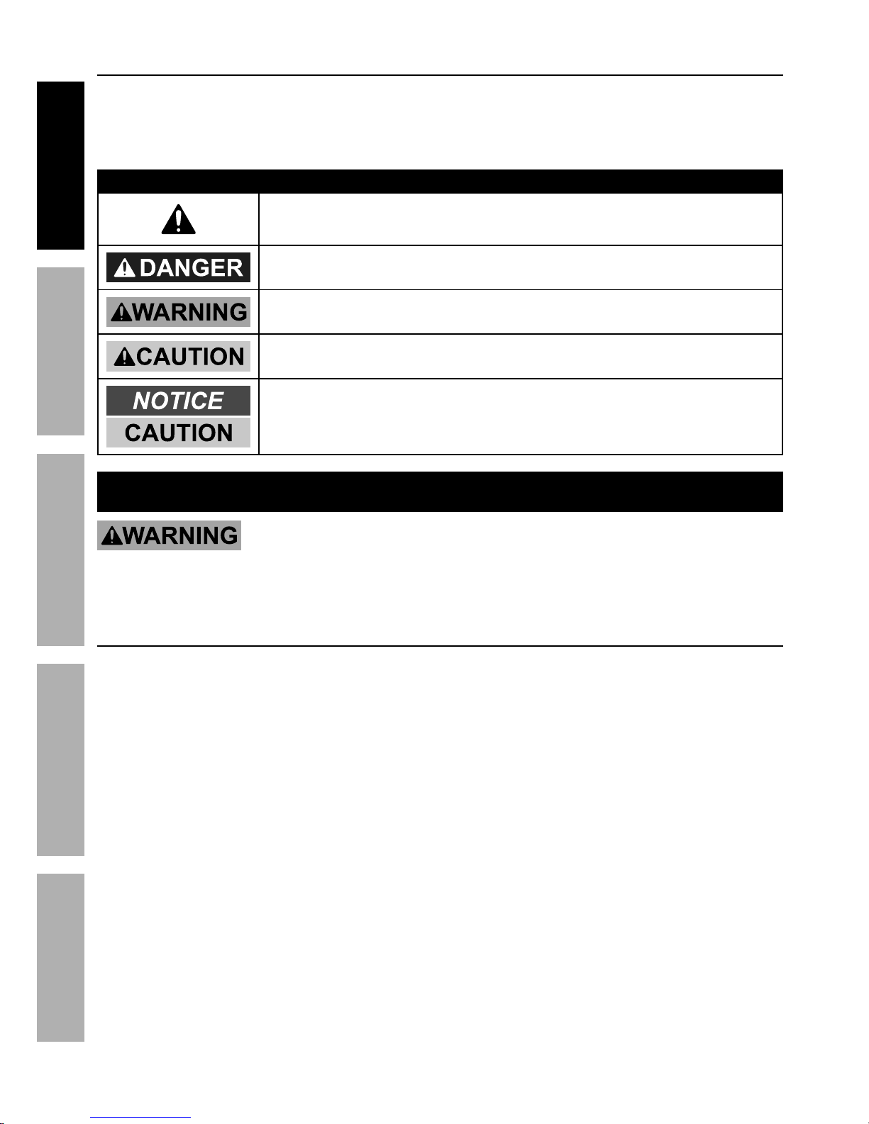
WARNING SYMBOLS AND DEFINITIONS
This is the safety alert symbol. It is used to alert you to potential
personal injury hazards. Obey all safety messages that
follow this symbol to avoid possible injury or death.
Indicates a hazardous situation which, if not avoided,
will result in death or serious injury.
Indicates a hazardous situation which, if not avoided,
could result in death or serious injury.
Indicates a hazardous situation which, if not avoided,
could result in minor or moderate injury.
Addresses practices not related to personal injury.
IMPORTANT SAFETY INFORMATION
Read all safety warnings and instructions.
Failure to follow the warnings and instructions may result in electric shock, fire and/or serious injury.
Save all warnings and instructions for future reference.
General Safety
PROTECT yourself and others. Read and understand this information.
1. Before use, read and understand
manufacturer′s instructions,
Material Safety Data Sheets (MSDS′s),
employer′s safety practices, and ANSI Z49.1.
2. Keep out of reach of children.
Keep children and bystanders away while operating.
3. Place the welder on a stable location before use.
If it falls while plugged in, severe injury,
electric shock, or fire may result.
4. Do not overreach.
Keep proper footing and balance at all times.
5. Stay alert, watch what you are doing and use
common sense when operating a welder.
Do not use a welder while you are tired or under
the influence of drugs, alcohol or medication.
A moment of inattention while operating welders
may result in serious personal injury.
6. Avoid unintentional starting. Make sure you are
prepared to begin work before turning on the Welder.
7. Never leave the Welder unattended while
energized. Turn power off if you have to leave.
8. The warnings, precautions, and instructions
discussed in this instruction manual cannot
cover all possible conditions and situations
that may occur. It must be understood by the
operator that common sense and caution are
factors which cannot be built into this product,
but must be supplied by the operator.
9. WARNING: This product, when used for
welding, plasma cutting, soldering, or similar
applications, produces chemicals known to
the State of California to cause cancer and
birth defects or other reproductive harm.
(California Health & Safety Code § 25249.5, et seq.)
10. WARNING: The cord of this product contains
lead and/or di (2-ethylhexyl) phthalate (DEHP),
chemicals known to the State of California
to cause cancer, and birth defects or other
reproductive harm. Wash hands after handling.
(California Health & Safety Code § 25249.5, et seq.)
Page 3For technical questions, please call 1-888-380-0318.Item 63617
SAFETYMAINTENANCE BASIC WELDINGWELDING TIPS SETUP
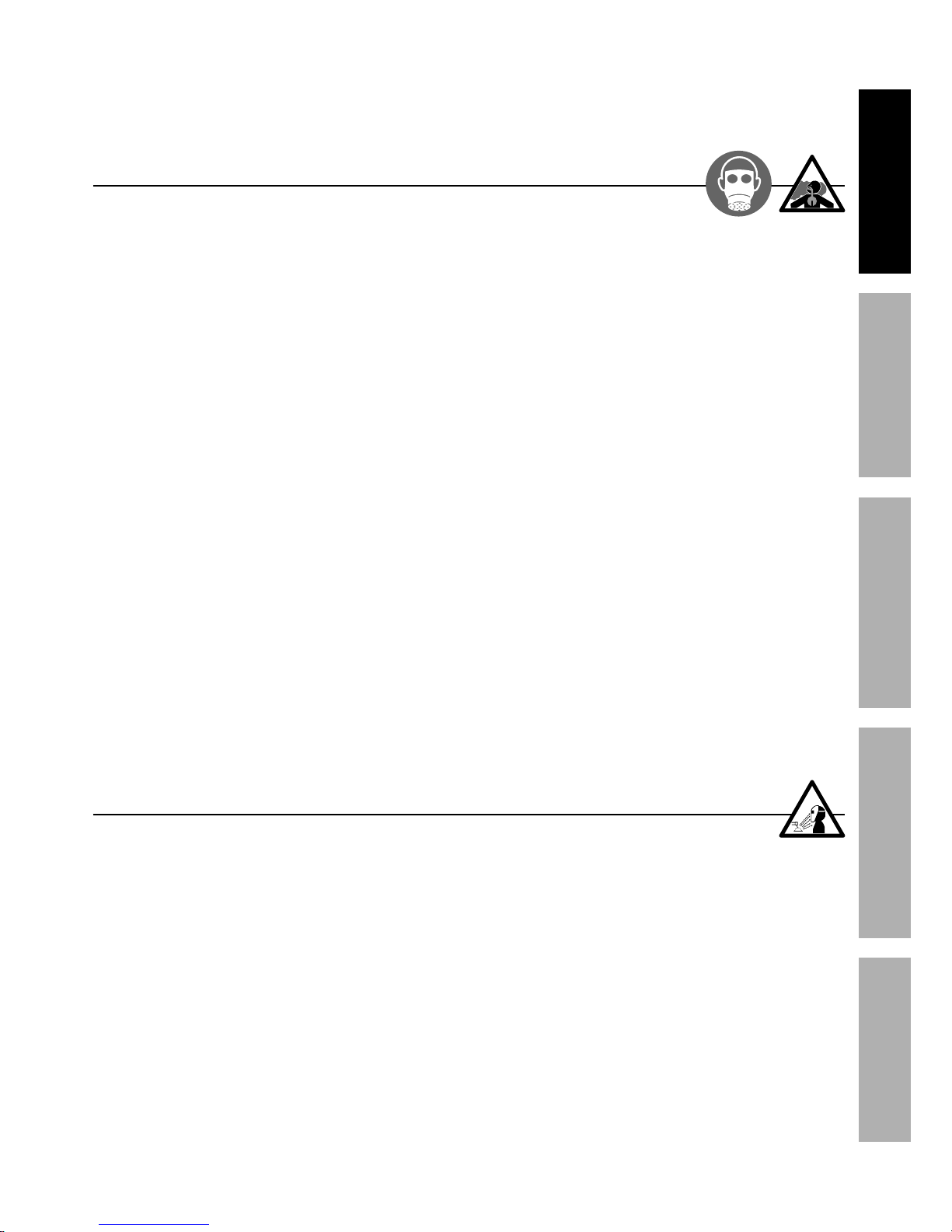
Fume and Gas Safety
INHALATION HAZARD:
Welding and Plasma Cutting Produce toxic fumes.
1. Exposure to welding or cutting exhaust
fumes can increase the risk of developing
certain cancers, such as cancer of the
larynx and lung cancer. Also, some diseases
that may be linked to exposure to welding
or plasma cutting exhaust fumes are:
• Early onset of Parkinson’s Disease
• Heart disease
• Ulcers
• Damage to the reproductive organs
• Inflammation of the small intestine or stomach
• Kidney damage
• Respiratory diseases such as
emphysema, bronchitis, or pneumonia
Use natural or forced air ventilation and wear
a respirator approved by NIOSH to protect
against the fumes produced to reduce the
risk of developing the above illnesses.
2. Do not use near degreasing or
painting operations.
3. Keep head out of fumes.
Do not breathe exhaust fumes.
4. Use enough ventilation, exhaust at arc, or
both, to keep fumes and gases from breathing
zone and general area. If engineering controls
are not feasible, use an approved respirator.
5. Work in a confined area only if it
is well-ventilated, or while wearing
an air-supplied respirator.
6. Have a recognized specialist in
Industrial Hygiene or Environmental Services
check the operation and air quality
and make recommendations
for the specific welding situation.
Follow OSHA guidelines for
Permissible Exposure Limits (PEL’s) and
the American Conference of Governmental
Industrial Hygienists recommendations for
Threshold Limit Values (TLV’s) for fumes and gases.
Arc Ray Safety
ARC RAYS can injure eyes and burn skin.
1. Wear ANSI-approved welding eye protection
featuring at least a number 10 shade lens rating.
2. Wear leather leggings, fire resistant shoes
or boots during use. Do not wear pants with
cuffs, shirts with open pockets, or any clothing
that can catch and hold molten metal or sparks.
3. Keep clothing free of grease, oil,
solvents, or any flammable substances.
Wear dry, insulating gloves and protective clothing.
4. Wear an approved head covering to protect
the head and neck. Use aprons, cape, sleeves,
shoulder covers, and bibs designed and
approved for welding and cutting procedures.
5. When welding/cutting overhead or in confined
spaces, wear flame resistant ear plugs or
ear muffs to keep sparks out of ears.
Page 4 For technical questions, please call 1-888-380-0318. Item 63617
SAFETY MAINTENANCEBASIC WELDING WELDING TIPSSETUP
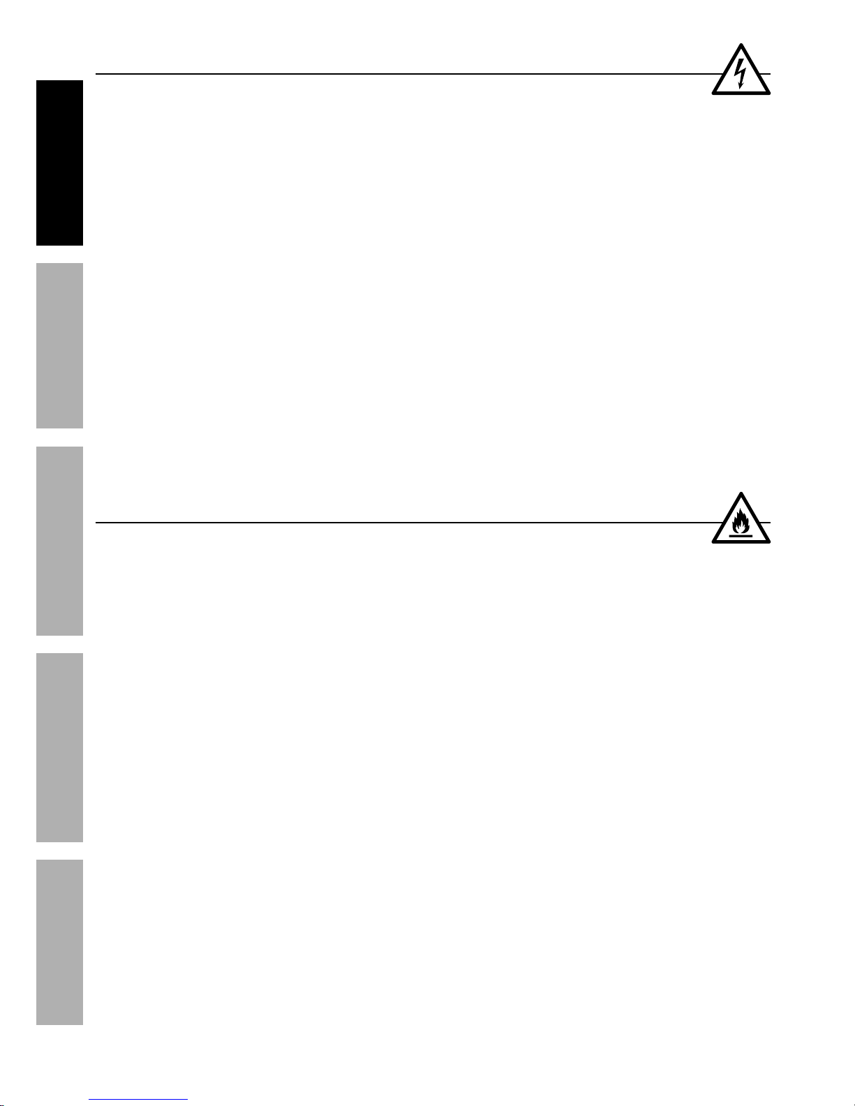
Electrical Safety
ELECTRIC SHOCK can KILL.
1. Turn off, disconnect power, and
discharge electrode to ground before setting
down torch/electrode holder and before service.
2. Do not touch energized electrical parts.
Wear dry, insulating gloves. Do not touch electrode
holder, electrode, welding torch, or welding wire with
bare hand. Do not wear wet or damaged gloves.
3. Connect to grounded, GFCI-protected
power supply only.
4. Do not use near water or damp objects.
5. People with pacemakers should consult their
physician(s) before use. Electromagnetic fields
in close proximity to heart pacemaker could cause
pacemaker interference or pacemaker failure.
6. Do not expose welders to rain or wet conditions.
Water entering a welder will increase
the risk of electric shock.
7. Do not abuse the cord. Never use the cord
for carrying, pulling or unplugging the welder.
Keep cord away from heat, oil, sharp edges
or moving parts. Damaged or entangled
cords increase the risk of electric shock.
8. Do not use outdoors.
9. Insulate yourself from the workpiece and
ground. Use nonflammable, dry insulating
material if possible, or use dry rubber mats,
dry wood or plywood, or other dry insulating
material large enough to cover your full
area of contact with the work or ground.
Fire Safety
ARC AND HOT SLAG can cause fire.
1. Clear away or protect flammable objects.
Remove or make safe all combustible materials for a
radius of 35 feet (10 meters) around the work area.
Use a fire resistant material to cover
or block all open doorways, windows,
cracks, and other openings.
2. Keep ABC-type fire extinguisher near
work area and know how to use it.
3. Maintain a safe working environment.
Keep the work area well lit.
Make sure there is adequate
surrounding workspace. Keep the work area free
of obstructions, grease, oil, trash, and other debris.
4. Do not operate welders in atmospheres
containing dangerously reactive or
flammable liquids, gases, vapors, or dust.
Provide adequate ventilation in work areas
to prevent accumulation of such substances.
Welders create sparks which may ignite flammable
substances or make reactive fumes toxic.
5. If working on a metal wall, ceiling, etc.,
prevent ignition of combustibles on the
other side by moving the combustibles to a
safe location. If relocation of combustibles is
not possible, designate someone to serve as
a fire watch, equipped with a fire extinguisher,
during the cutting process and for at least one
half hour after the cutting is completed.
6. Do not weld or cut on materials having
a combustible coating or combustible
internal structure, as in walls or ceilings, without
an approved method for eliminating the hazard.
7. Do not dispose of hot slag in containers
holding combustible materials.
8. After welding, make a thorough examination
for evidence of fire. Be aware that easily
visible smoke or flame may not be present
for some time after the fire has started.
9. Do not apply heat to a container that has held
an unknown substance or a combustible
material whose contents, when heated,
can produce flammable or explosive vapors.
Clean and purge containers before applying heat.
Vent closed containers, including castings,
before preheating, welding, or cutting.
Page 5For technical questions, please call 1-888-380-0318.Item 63617
SAFETYMAINTENANCE BASIC WELDINGWELDING TIPS SETUP
Welder Use and Care
1. Do not use the welder if the switch does not turn
it on and off. Any welder that cannot be controlled
with the switch is dangerous and must be repaired.
2. Disconnect the plug from the power
source before making any adjustments,
changing accessories, or storing welders.
Such preventive safety measures reduce the
risk of starting the welder accidentally.
3. Prevent unintentional starting.
Ensure the switch is in the offposition before connecting to power
source or moving the welder. Carrying
or energizing welders that have the
switch on invites accidents.
4. Store idle welders out of the reach of
children and do not allow persons unfamiliar
with the welder or these instructions to
operate the welder. Welders are dangerous
in the hands of untrained users.
5. Use the welder and accessories in
accordance with these instructions, taking
into account the working conditions and
the work to be performed. Use of the welder
for operations different from those intended
could result in a hazardous situation.
6. Do not use the welder for pipe thawing.
Maintenance
1. Maintain welders. Check for misalignment or
binding of moving parts, breakage of parts
and any other condition that may affect the
welder’s operation. If damaged, have the
welder repaired before use. Many accidents
are caused by poorly maintained welders.
2. Have your welder serviced by a qualified
repair person using only identical
replacement parts. This will ensure that
the safety of the welder is maintained.
3. Maintain labels and nameplates on the Welder.
These carry important information.
If unreadable or missing, contact
Harbor Freight Tools for a replacement.
4. Unplug before maintenance. Unplug the Welder
from its electrical outlet before any inspection,
maintenance, or cleaning procedures.
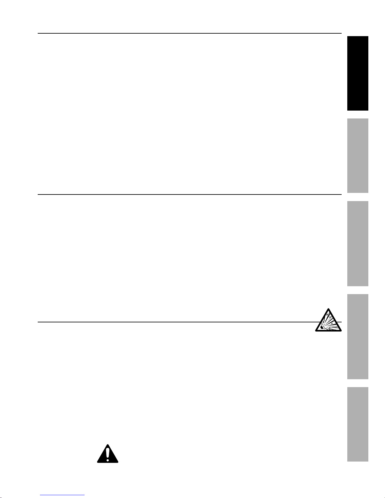
Gas Shielded Welding – Cylinder Safety
Cylinders can explode when damaged.
1. Never weld on a pressurized or a closed cylinder.
2. Never allow an electrode holder,
electrode, welding torch, or welding
wire to touch the cylinder.
3. Keep cylinders away from any electrical circuits,
including welding circuits.
4. Keep protective cap in place over the valve
except when the cylinder is in use.
5. Use only correct gas shielding equipment
designed specifically for the type of welding
you will do. Maintain this equipment properly.
6. Protect gas cylinders from heat, being struck,
physical damage, slag, flames, sparks, and arcs.
7. Always use proper procedures
to move cylinders.
SAVE THESE INSTRUCTIONS.

Page 6 For technical questions, please call 1-888-380-0318. Item 63617
SAFETY MAINTENANCEBASIC WELDING WELDING TIPSSETUP
Grounding
TO PREVENT ELECTRIC SHOCK AND DEATH
FROM INCORRECT GROUNDING WIRE CONNECTION:
Check with a qualified electrician if you are in doubt as to whether the outlet is
properly grounded.
Do not use the Welder if the power cord or plug is damaged. If damaged, have it repaired by a service
facility before use. If the plug will not fit the outlet, have a proper outlet installed by a qualified electrician,
do not use adapter plugs.
1. The green wire inside the cord is connected to
the grounding system in the Welder. The green
wire in the cord must be the only wire connected
to the Welder’s grounding system and must
never be attached to an electrically “live” terminal.
Never leave the grounding wire disconnected
or modify the Power Cord Plug in any way.
2. Make sure the tool is connected to an outlet having
the same configuration as the plug. If the tool must
be reconnected for use on a different type of electric
circuit, the reconnection should be made by qualified
service personnel; and after reconnection, the tool
should comply with all local codes and ordinances.
Extension Cords
Do not use an extension cord on this Welder.
Replacement Cords
1. Use only one of the supplied power cords for
this Welder or an identical replacement cord.
2. Do not install a thinner or longer
cord on this Welder.
3. Do not patch cords of any length
together for this item. Patches may allow
moisture to penetrate the insulation,
resulting in electric shock.
Page 7For technical questions, please call 1-888-380-0318.Item 63617
SAFETYMAINTENANCE BASIC WELDINGWELDING TIPS SETUP
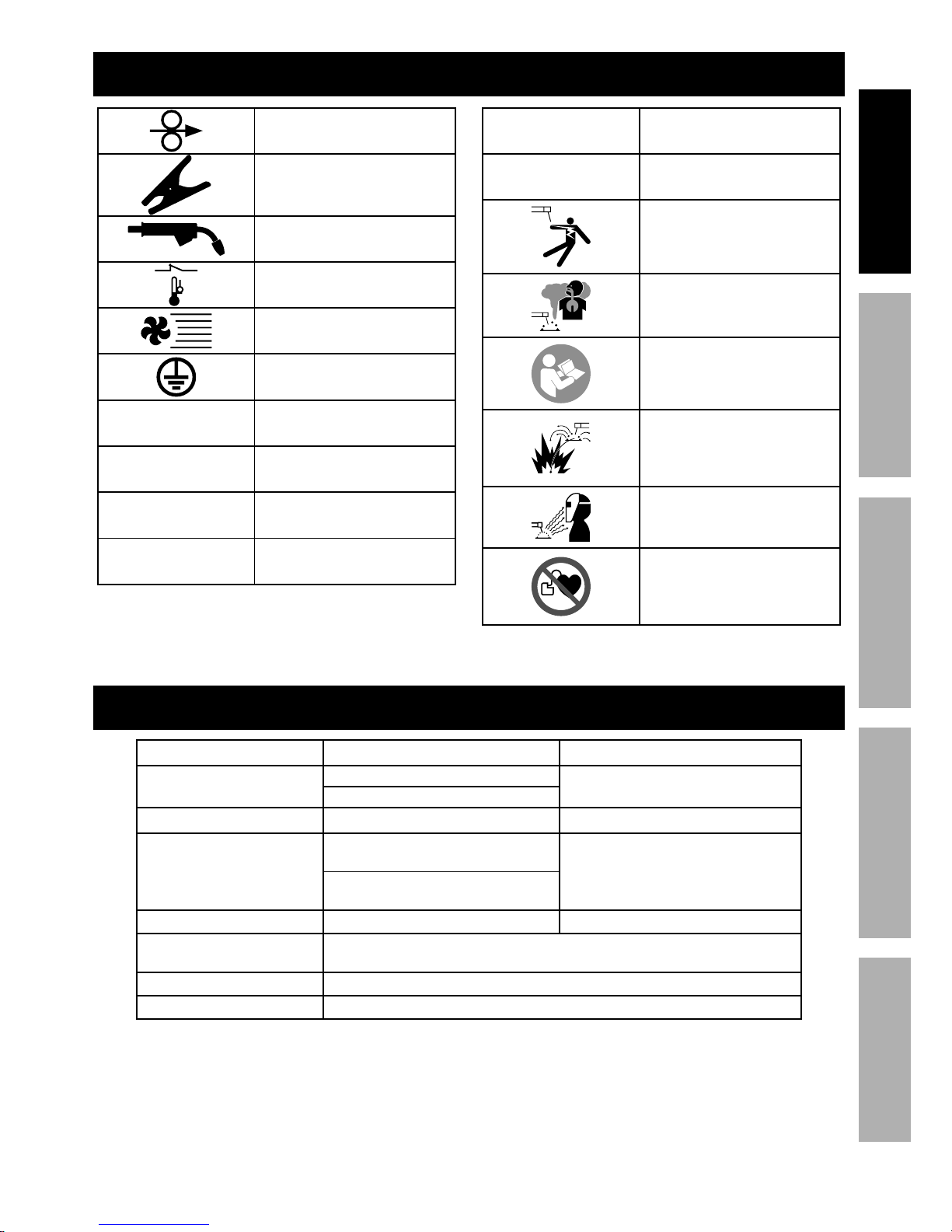
Symbology
Wire Feed (Speed)
Workpiece Ground Cable
Torch Cable
Overheat Shutdown Indicator
Cooling Fan
Housing Ground Point
VAC
Volts Alternating Current
A
Amperes
OCV
Open Circuit Voltage
KVA
Kilovolt Amperes
(Volts / 1000 * Amperes)
IPM
Inches Per Minute
AWG
American Wire Gauge
Electric Shock Hazard.
Do not touch energized parts.
Inhalation Hazard.
Keep head out of fumes
and use proper ventilation.
Read manual before
setup and/or use.
Fire Hazard.
Keep flammable materials
away during welding. Spatter
can cause accidental fires.
Arc Ray Hazard.
Wear welding helmet with
properly rated filter lens.
Pacemaker Hazard.
Welding processes may
interfere with pacemakers.
Consult doctor before use.
Specifications
Power Input 120 VAC / 60 Hz 240 VAC / 60 Hz
Current Input at Output
15 A: 20.7 A at 100 A
24.8 A at 200 A
20 A: 24.3 A at 115 A
Welding Current Range 30 –140 A 30 –220 A
Rated Duty Cycles
15 A:
40% @ 100 A
100% @ 75 A
25% @ 200 A
100% @ 115 A
20 A:
30% @ 115 A
100% @ 75 A
Open Circuit Voltage 78 VDC 78 VDC
Welding Wire Capacity
Solid Core: 0.025" / 0.030" / 0.035"
Flux Cored: 0.030" / 0.035" / 0.045"
Wire Speed 50 – 500 IPM
Wire Spool Capacity Up to 12 lb spool
Page 8 For technical questions, please call 1-888-380-0318. Item 63617
SAFETY MAINTENANCEBASIC WELDING WELDING TIPSSETUP
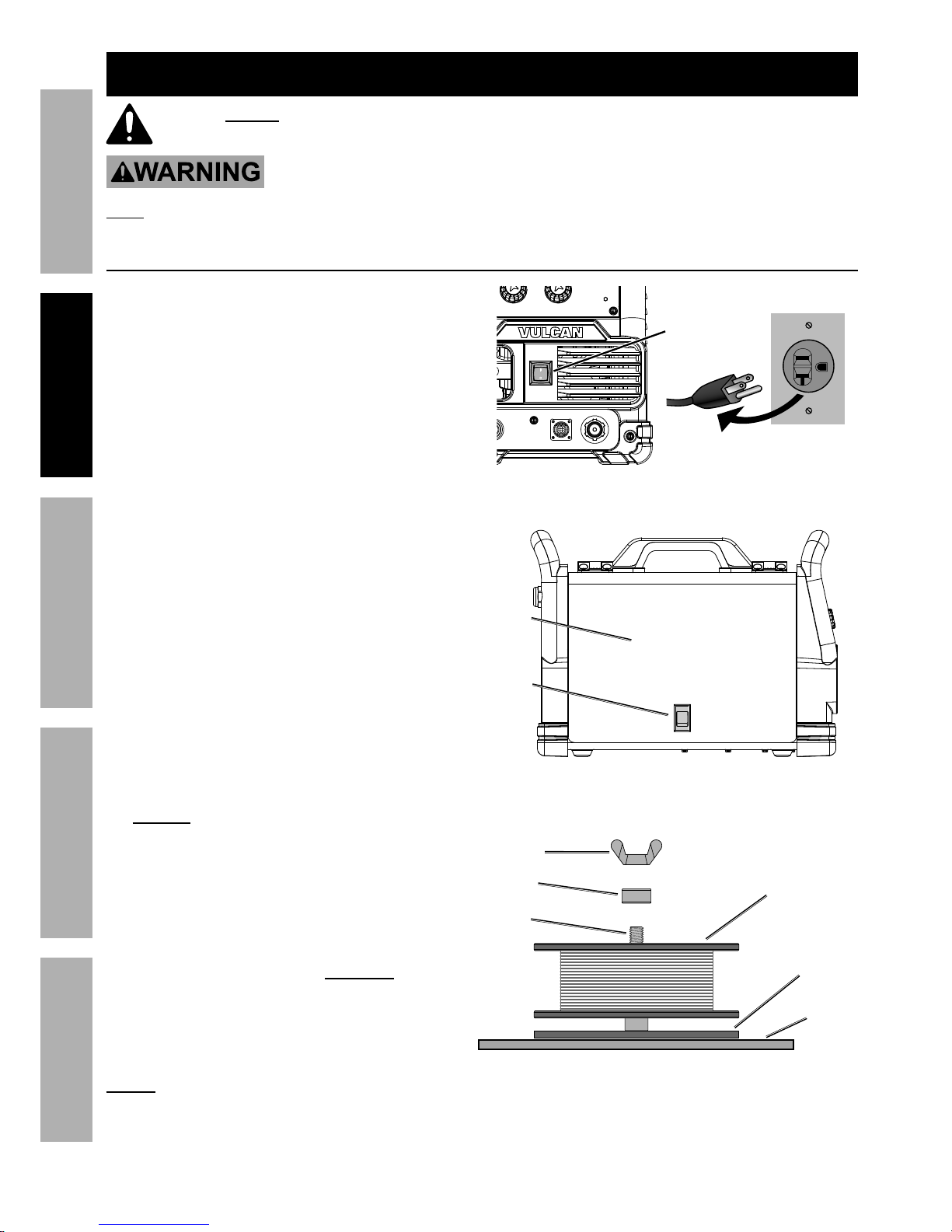
1. Turn the Power Switch OFF and unplug
the Welder before proceeding.
2. Pull up on the Door Latch,
then open the Door.
3. 2 Pound Wire Spool Installation:
Remove the Wingnut and Spacer. If
replacing a Spool, remove the old Spool
and all remaining wire from the liners.
4. Place the new Wire Spool over the Spool Spindle
and against the Spool Brake Pad as illustrated.
To prevent wire feed problems, set the
Spool so that it will unwind clockwise.
Power
Switch
Door
Latch
Door
Welder
Wall
Wingnut
2 lb
Wire Spool
Spool
Brake Pad
Spacer
Spool
Spindle
2 lb Spool Loading
Setup
Read the ENTIRE IMPORTANT SAFETY INFORMATION section at the beginning of this manual
including all text under subheadings therein before set up or use of this product.
TO PREVENT SERIOUS INJURY FROM ACCIDENTAL OPERATION:
Turn the Power Switch off and unplug the Welder before setup.
Note: Remove the protective foam and cardboard from the Welder before setup.
Wire Spool Installation / Wire Setup
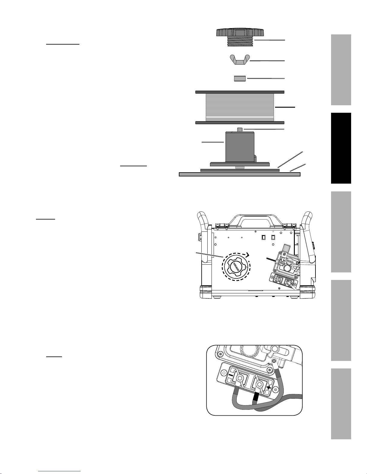
5. Replace the Spacer over the
Spool Spindle and secure Spool
in place with the Wingnut.
Notice: If Wire Spool can spin freely, Wingnut is too
loose. This will cause the welding wire to unravel and
unspool which can cause tangling and feeding problems.
Page 9For technical questions, please call 1-888-380-0318.Item 63617
SAFETYMAINTENANCE BASIC WELDINGWELDING TIPS SETUP
6. 10-12 Pound Wire Spool Installation:
Remove the Wingnut and Spacer. If
replacing a Spool, remove the old Spool
and all remaining wire from the liners.
7. Place the Spool Adapter over the Spool Spindle
and against the Spool Brake Pad as illustrated.
8. Place the new Wire Spool over the Adapter and
line up pin on Adapter with hole in Spool.
To prevent wire feed problems, set the
Spool so that it will unwind clockwise.
9. Replace the Spacer over the Spool Spindle
and secure Spool in place with the Wingnut.
Notice: If Wire Spool can spin freely, Wingnut
is too loose. This will cause the welding
wire to unravel and unspool which can
cause tangling and feeding problems.
10. Screw the Spool Knob into the Spool Adapter.
11. DCEN Direct Current Electrode Negative
Wire Setup for Flux-Cored (gasless) welding:
Remove the two Wingnuts securing the cables.
Connect the Black Ground Cable to the positive (+)
Terminal using the Wingnut.
Connect the Red Cable to the negative (–)
Terminal using the other Wingnut.
Make sure the Cable connectors
sit flush in the grooves.
Welder
Wall
Spool
Brake Pad
10-12 lb
Spool
Adapter
10-12 lb Spool Loading
Wingnut
10-12 lb
Wire Spool
Spacer
Spool Spindle
Spool Knob
Wire
must
unwind
in this
direction
DCEN
Flux-Cored (Gasless) Polarity Setup

Page 10 For technical questions, please call 1-888-380-0318. Item 63617
SAFETY MAINTENANCEBASIC WELDING WELDING TIPSSETUP
b. Determine which type of shielding gas
would be appropriate for the welding
you will do. Refer to the Settings Chart
on the inside of the Welder door.
c. With assistance, set the cylinder (not included)
onto a cabinet or cart near the Welder
and secure the cylinder in place with two
straps (not included) to prevent tipping.
d. Remove the cylinder’s cap. Stand to the
side of the valve opening, then open the
valve briefly to blow dust and dirt from the
valve opening. Close the cylinder valve.
e. Locate the Regulator (included) and close its
valve until it is loose, then thread Regulator
onto cylinder and wrench tighten connection.
Note: When using C100 shielding gas, connect the
enclosed CGA 580/320 adapter to the inlet connection
of the Regulator and wrench tighten. Thread the
adapter onto the gas cylinder and wrench tighten.
f. Attach the Gas Hose (included) to the
Regulator’s outlet and the Welder’s gas
inlet. Wrench-tighten both connections.
Reset
Power Input
Gas Inlet
f
e
c
Briefly open valve
to clean,
then close
valve.
d
12. DCEP Direct Current Electrode Positive Wire
Setup for Solid Core (gas shielded) welding:
a. Remove the two Wingnuts securing the
cables. Connect the Black Ground Cable to the
negative (–) Terminal using the Wingnut.
Connect the Red Cable to the positive (+)
Terminal using the other Wingnut.
Make sure the Cable connectors
sit flush in the grooves.
DCEP
Solid Core (Gas Shielded) Polarity Setup
Page 11For technical questions, please call 1-888-380-0318.Item 63617
SAFETYMAINTENANCE BASIC WELDINGWELDING TIPS SETUP
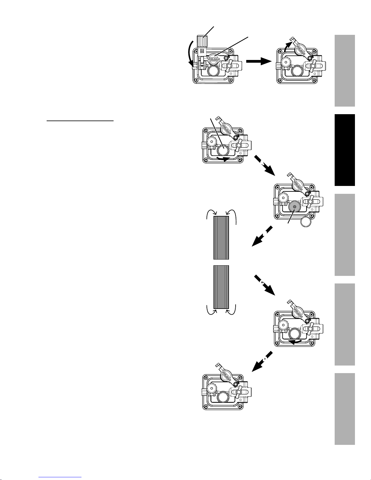
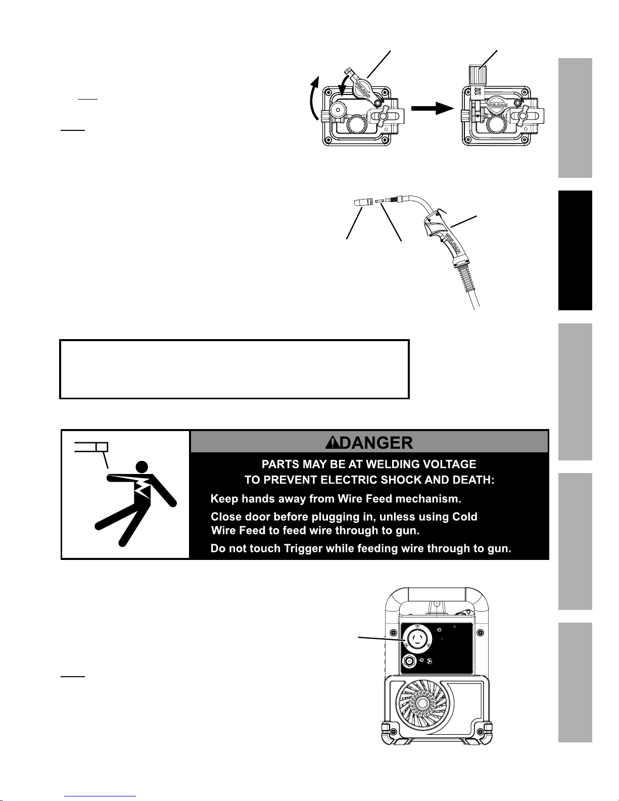
13. Turn the Feed Tensioner knob counterclockwise to
loosen it enough to pull it down to remove tension.
The spring-loaded Idler Arm will move up as shown.
14. Feed Roller Instructions:
Check that the Feed Roller is correct for the
type of wire being used (solid core or fluxcored) and that it is turned to properly match
the wire size marked on the Wire Spool:
a. Unscrew the Feed Roller Knob counterclockwise.
b. Remove the Feed Roller Knob to
expose the Feed Roller.
c. Flip or replace the Feed Roller as needed and
confirm that it is the correct Roller for the type of
wire being used and that the number showing
is the same as the wire diameter on the Spool.
d. Screw the Feed Roller Knob back into
place to secure the Feed Roller.
Idler Arm
Feed Tensioner
Feed Roller
Knob
Feed
Roller
A
B
C
D
0.030 / 0.035
groove
0.025
groove
Solid Core
V-Groove
0.045
groove
0.030 / 0.035
groove
Flux-Cored
Knurled Groove
Page 12 For technical questions, please call 1-888-380-0318. Item 63617
SAFETY MAINTENANCEBASIC WELDING WELDING TIPSSETUP
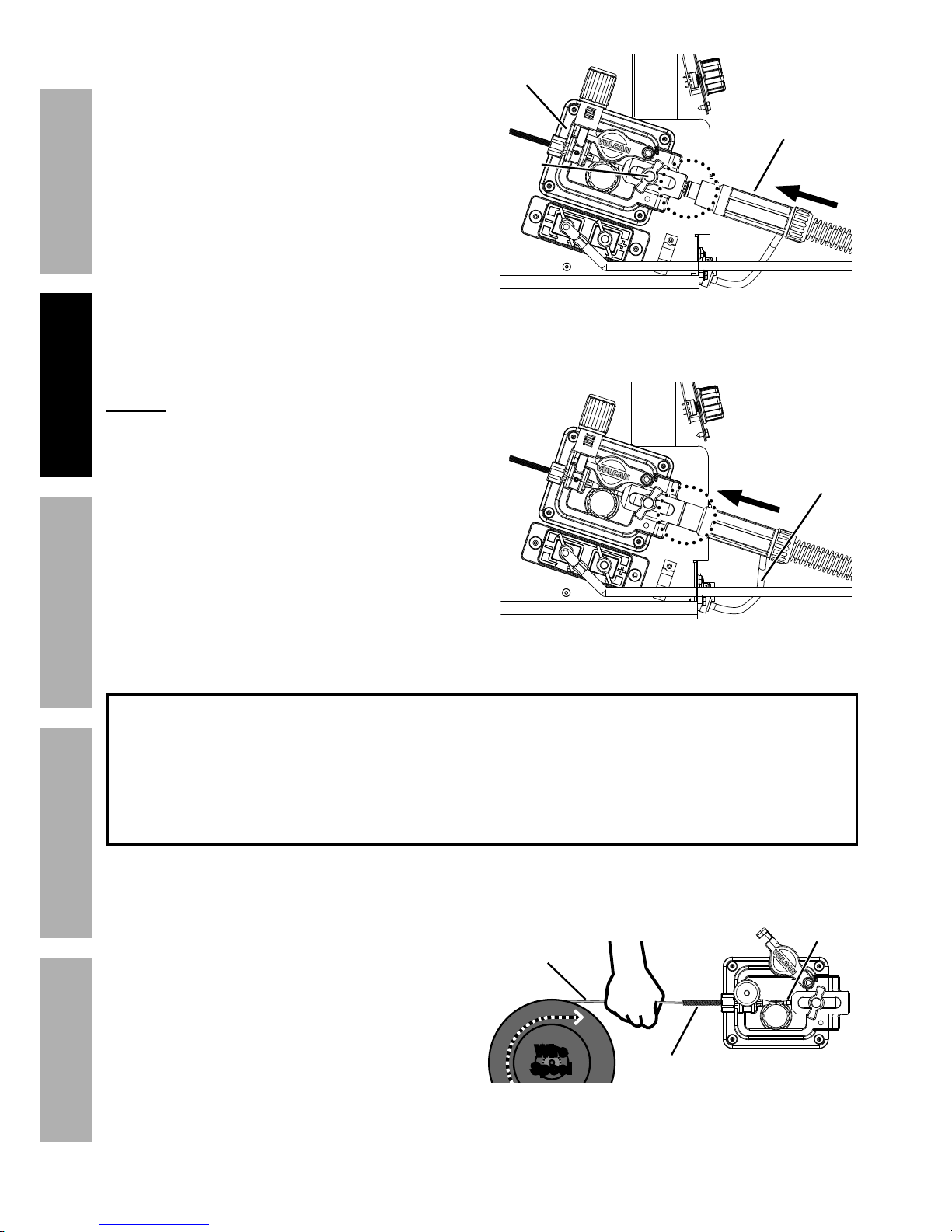
15. Loosen the Knob on the Wire Feed
mechanism, then insert the Gun Cable
Connector through the hole on the Welder
front and into the socket on the Wire Feed.
16. Ensure that the Gun Cable Connector
is fully inserted into the socket on
the Wire Feed mechanism as shown,
then tighten the Knob securely.
If Connector is not fully inserted, the gas
connection will leak, preventing shielding
gas from reaching the welding arc.
NOTICE: To prevent damage, do
not overtighten the Knob.
17. Connect the Wire Feed Control Cable to the
Wire Feed Control Socket located on the front
of the machine and tighten the lock ring on the
Cable plug. Note that the plug on the Cable fits
into the Socket in one specific orientation only.
IMPORTANT
Securely hold onto the end of the welding wire and keep
tension on it during the following steps.
If this is not done, the welding wire will unravel and unspool
which can cause tangling and feeding problems.
18. Cut off all bent and crimped wire.
The cut end must have no burrs or
sharp edges; cut again if needed.
19. Keep tension on the wire and guide at
least 12 inches of wire into the Wire
Inlet Liner and Feed Guide.
Gun Cable
Connector
Incorrect – Connector not fully inserted
Wire Feed
Mechanism
Knob
Correct – Connector fully inserted
Wire
Feed
Control
Cable
Wire
Spool
Welding
Wire
HOLD WIRE
SECURELY
Feed
Guide
Wire Inlet
Liner
Page 13For technical questions, please call 1-888-380-0318.Item 63617
SAFETYMAINTENANCE BASIC WELDINGWELDING TIPS SETUP
20. Make sure the welding wire is resting in the groove
of the Feed Roller, then push the wire Idler Arm
down, and swing the Feed Tensioner up to latch it
across the tip of the arm.
After the wire is held by the Tensioner,
you may release it.
Note: The tension should be 3 – 5 for solid wire and
2 – 3 for flux-cored wire. Too much force on flux-cored
wire will crush it and may cause feeding issues.
21. Pull the Nozzle to remove it.
22. Unscrew the Contact Tip
counterclockwise and remove.
23. Lay the MIG Gun Cable out in a straight line so
that the welding wire moves through it easily.
Leave the cover open, so that the feed
mechanism can be observed.
1.
2.
3.
24. Plug either 120 VAC or 240 VAC Power
Cord into Power Input Socket.
Note: Plug will only fit one way.
Idler Arm Feed Tensioner
Nozzle
Contact
Tip
MIG Gun
IMPORTANT
Stainless steel wire is less flexible than other welding wire. Therefore, it is
more difficult to feed through the liner and gun. It is especially important
to keep the gun cable straight while feeding stainless steel wire.
Reset
Power Input
Gas Inlet
Power
Input
Page 14 For technical questions, please call 1-888-380-0318. Item 63617
SAFETY MAINTENANCEBASIC WELDING WELDING TIPSSETUP
25. Do not touch the Gun’s Trigger. Plug the Power
Cord into a properly grounded, GFCI protected
120 VAC (20 amp rated) or 240 VAC receptacle that
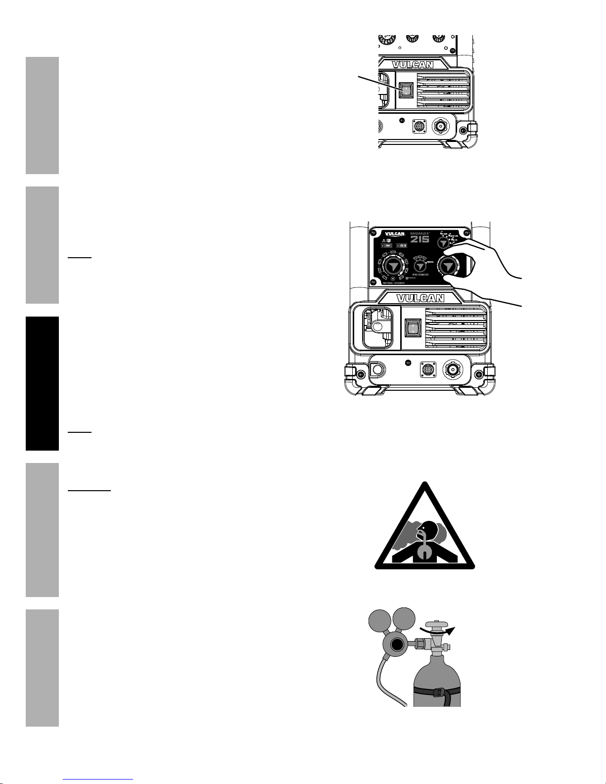
matches the plug and turn the Power Switch ON.
The circuit must be equipped with delayed
action-type circuit breaker or fuses.
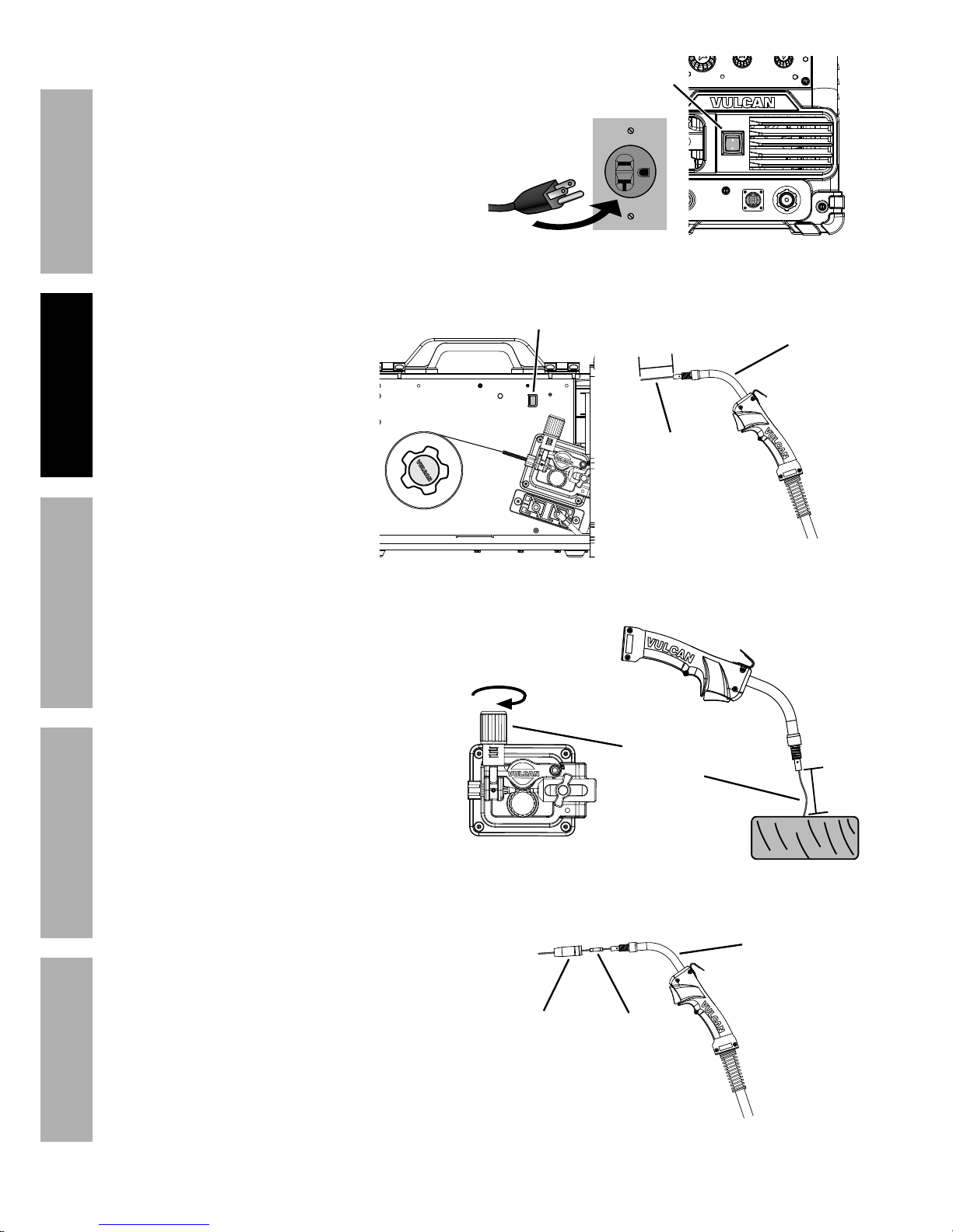
26. Point the Gun away from
all objects. Press and
hold the Cold Wire Feed
Switch until the wire feeds
through two inches.
The wire liner may come
out with the welding
wire. This is normal,
just push the wire liner
back into the Gun.
If the wire does not feed
properly and the Spool
is stationary, turn OFF
and unplug the Welder
and slightly tighten the
Feed Tensioner clockwise
before retrying.
27. To check the wire’s drive tension, feed the
wire against a piece of wood from 2 to 3
inches away. If the wire stops instead
of bending, unplug the Welder, slightly
tighten the Feed Tensioner clockwise, and
try again. If the wire bends from the feed
pressure, then the tension is set properly.
28. Turn OFF the Power Switch and unplug the
Power Cord from its electrical outlet.
29. Select a Contact Tip that is compatible with
the welding wire used. Slide the Contact
Tip over the wire and thread it clockwise into
the MIG Gun. Tighten the Contact Tip.
30. Replace the Nozzle and cut the wire
off at 1/2" from tip (1/2" stickout).
31. Close the Welder Door. Make sure
Door is securely latched.
Power
Switch
MIG Gun
Welding
Wire
2"
Cold Wire
Feed Switch
Incrementally
increase tension
until
wire bends.
2–3"
Nozzle
Contact
Tip
MIG Gun
Page 15For technical questions, please call 1-888-380-0318.Item 63617
SAFETYMAINTENANCE BASIC WELDINGWELDING TIPS SETUP
Basic Welding
Read the ENTIRE IMPORTANT SAFETY INFORMATION section at the beginning of this manual
including all text under subheadings therein before welding.
TO PREVENT SERIOUS INJURY:
Protective gear must be worn when using the Welder; minimum shade number 10 full face shield
(or welding mask), ear protection, welding gloves, sleeves and apron, NIOSH-approved respirator, and fire
resistant work clothes without pockets should be worn when welding.
Light from the arc can cause permanent damage to the eyes and skin.
Do not breathe arc fumes.
Flux-cored wire welding is used to weld mild steel
and stainless steel without shielding gas.
MIG welding uses solid wire and shielding gas,
and is used to weld mild steel and stainless steel.
MIG welding can also be used to weld thinner
workpieces than flux-cored welding can.
Aluminum welding can be performed with an
optional Spool Gun (sold separately) using
aluminum wire and shielding gas.
Good welding takes a degree of skill and experience.
Practice a few sample welds on scrap before
welding your first project. Additional practice
periods are recommended whenever you weld:
• a different thickness of material
• a different type of material
• a different type of connection
• using a different process (MIG vs. Flux)
Make practice welds on pieces of scrap to practice
technique before welding anything of value.
Practice your welding
technique on scrap
pieces before welding
anything of value.
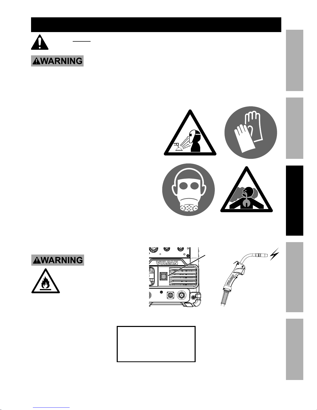
TO PREVENT SERIOUS INJURY,
FIRE AND BURNS:
Keep welding tip clear of grounded
objects whenever unit is plugged
in and turned on.
Power
On
=
Page 16 For technical questions, please call 1-888-380-0318. Item 63617
SAFETY MAINTENANCEBASIC WELDING WELDING TIPSSETUP
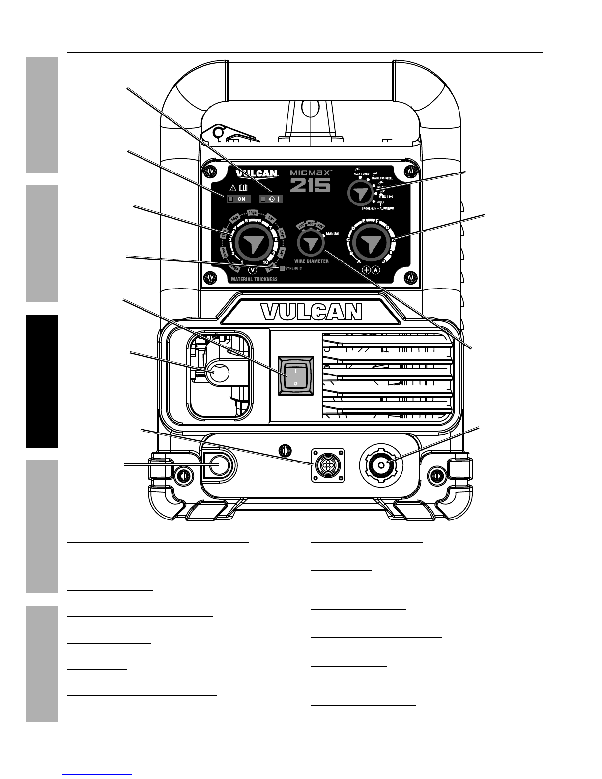
Front Panel Controls
Voltage Input / Thermal Overload Indicator:
Lights up if the input voltage is outside the
machine’s specifications or duty cycle has been
exceeded, resulting in overheating the Welder.
Power ON Indicator: When illuminated
indicates that the Power Switch is on.
Material Thickness / Voltage Knob: This
controls the output voltage of the Welder.
Synergic Indicator: Lights when using Auto Settings
and flashes if chosen settings are incorrect.
Power Switch: Turns on power to the
Welder and internal cooling fan.
MIG Gun / Spool Gun Cable Socket: The MIG Gun
and Spool Gun Cables connect here. The wire,
welding current, and shielding gas (if performing
MIG) feed to the weld through here.
Wire Feed Control Socket: The MIG Gun and
Spool Gun Control Cables connect here.
Ground Cable: This connects to the base
metal to provide a good connection for the
current to travel back to the Welder.
Spool Gun Gas Outlet: When using optional Spool
Gun (sold separately), gas hose connects here.
Wire Diameter Selection Knob: Sets the
diameter of the welding wire to be used.
Wire Speed Knob: Controls the speed that the
welding wire feeds out of the MIG Gun or Spool
Gun and the output amperage of the Welder.
Process Selection Knob: Adjust to select
the welding process to be used.
Wire Speed
Knob
Wire Diameter
Selection Knob
Process
Selection Knob
Material
Thickness /
Voltage Knob
Wire Feed
Control Socket
Ground
Cable
Power
Switch
Voltage
Input /
Thermal
Overload
Indicator
Power ON
Indicator
Spool Gun
Gas Outlet
MIG Gun /
Spool Gun
Cable Socket
Synergic
Indicator
Page 17For technical questions, please call 1-888-380-0318.Item 63617
SAFETYMAINTENANCE BASIC WELDINGWELDING TIPS SETUP
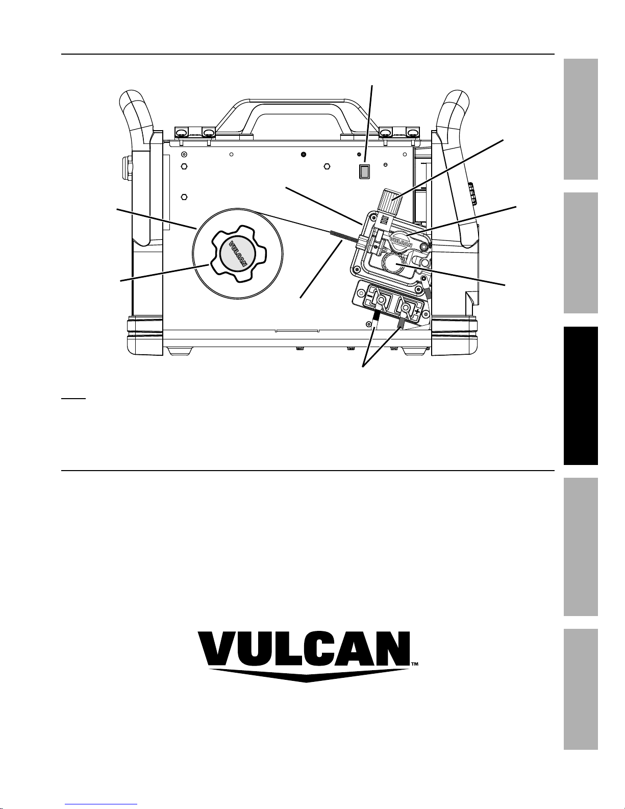
Interior Controls
Cold Wire
Feed Switch
Idler
Arm
Wire Feed
Mechanism
Wire Spool
Spool Knob
Polarity Cables
Feed
Tensioner
Wire Inlet
Liner
Feed
Roller Knob
Note: When using an optional Spool Gun (sold separately), connect the Spool Gun gas
hose to the Spool Gun Gas Outlet (see Front Panel Controls on previous page).
Weld Settings
Refer to the Settings Chart on the inside of the Welder door for Flux-Cored and MIG Weld
settings. The chart is only intended to show general guidelines for different wire sizes and for
different thicknesses of material. The initial settings used at the beginning of a weld may need to be
adjusted after stopping and carefully inspecting the weld. Proper welding takes experience.
Page 18 For technical questions, please call 1-888-380-0318. Item 63617
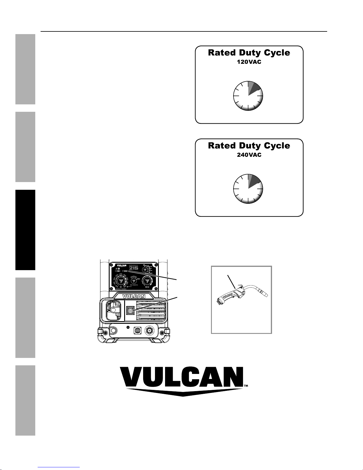
SAFETY MAINTENANCEBASIC WELDING WELDING TIPSSETUP
Avoid damage to the Welder by not welding
for more than the prescribed duty cycle
time. The Duty Cycle defines the number of
minutes, within a 10 minute period, during
which a given welder can produce a particular
welding current without overheating.
For example, a welder with a 40% duty
cycle at 100 A welding current must be
allowed to rest for at least 6 minutes after
every 4 minutes of continuous welding.
Failure to carefully observe duty cycle limitations
can easily over-stress a welder’s power generation
system contributing to premature welder failure.
This Welder has an internal thermal protection
system to help prevent this sort of over-stress.
When the Welder overheats, it automatically
shuts down and the Overload Indicator
lights. The Welder automatically returns to
service after cooling off. Should this occur,
rest the MIG Gun on an electrically nonconductive, heat-proof surface, such as a
concrete slab, well clear of the ground clamp.
Allow the Welder to cool with the Power
Switch on, so that the internal Fan will help
cool the Welder.
When the Overload Indicator is no longer
lit and the Welder can be used again, use
shorter welding periods and longer rest
periods to prevent needless wear.
100% Continuous Use at 115A
25% Use at 200A
For 10 Continuous Minutes
2-1/2
Minutes
Welding
7-1/2
Minutes
Resting
100% Continuous Use at 75A
40% Use at 100A
For 10 Continuous Minutes
4
Minutes
Welding
6
Minutes
Resting
Power
Switch
Overload
Indicator
MIG Gun
concrete slab
(or other heat-proof,
non-conductive surface)
Duty Cycle (Duration of Use)
Page 19For technical questions, please call 1-888-380-0318.Item 63617
SAFETYMAINTENANCE BASIC WELDINGWELDING TIPS SETUP
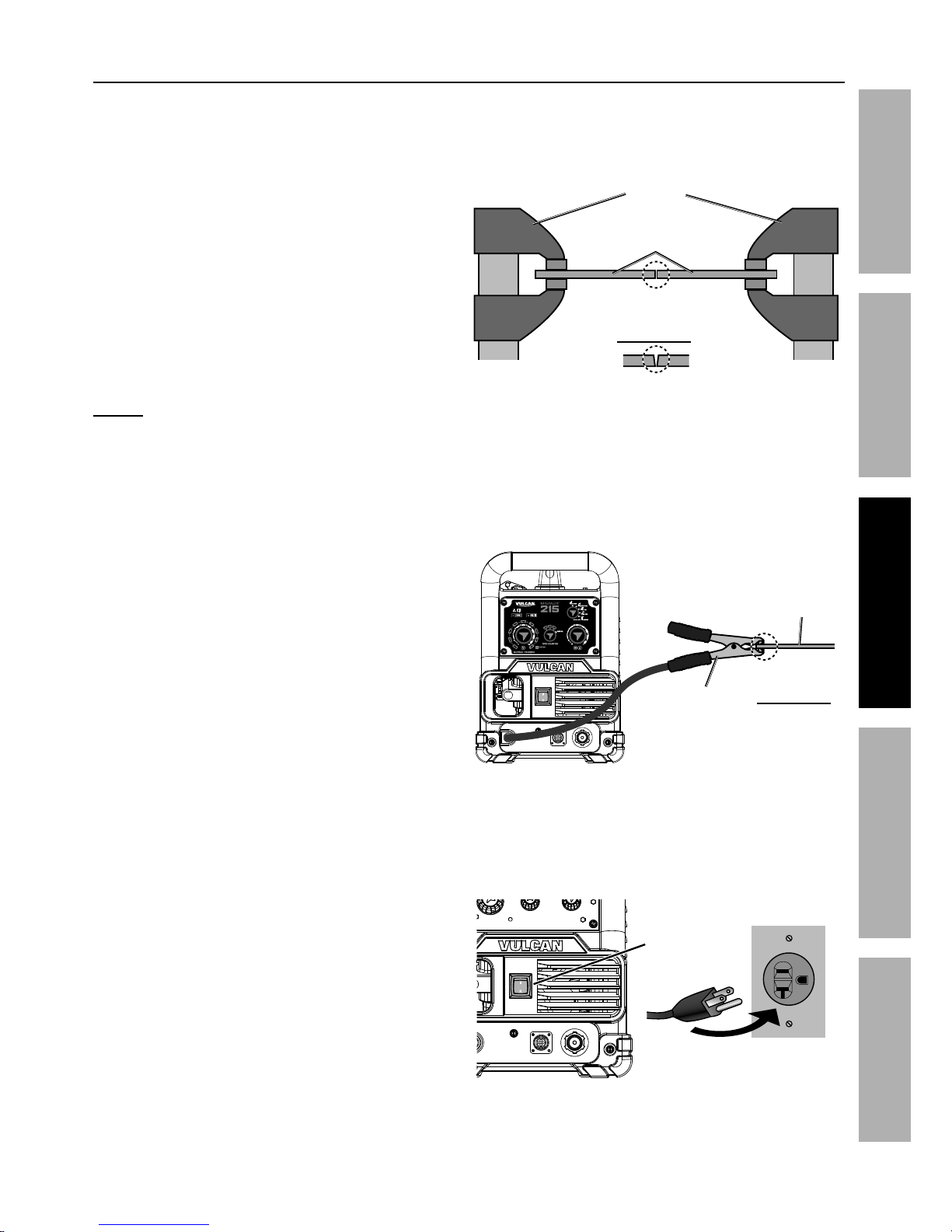
1. Make practice welds on pieces of scrap the
same thickness as your intended workpiece
to practice technique before welding anything
of value. Clean the weld surfaces thoroughly
with a wire brush or angle grinder; there
must be no rust, paint, oil, or other materials
on the weld surfaces, only bare metal.
2. Use clamps (not included) to hold the workpieces
in position so that you can concentrate on
proper welding technique. The distance
(if any) between the two workpieces must be
controlled properly to allow the weld to hold
both sides securely while allowing the weld
to penetrate fully into the joint. The edges of
thicker workpieces may need to be chamfered
(or beveled) to allow proper weld penetration.
Notice: When welding equipment on a vehicle,
disconnect the vehicle battery power from both the
positive connection and the ground before welding.
This prevents damage to some vehicle electrical
systems and electronics due to the high voltage
and high frequency bursts common in welding.
3. Clamp Ground Cable to bare metal on the
workpiece near the weld area, or to metal work
bench where the workpiece is clamped.
4. Turn the Power Switch to the OFF position,
then plug the Power Cord into a properly
grounded, GFCI protected 120 VAC (20 amp
rated) or 240 VAC receptacle that matches
the plug. The circuit must be equipped with
delayed action-type circuit breaker or fuses.
clamps
workpieces
Chamfer thick workpieces.
Clean
surfaces to
bare metal.
Workpiece
Ground
Clamp
Clean
surface to
bare metal.
Power
Switch
Setting Up The Weld
Page 20 For technical questions, please call 1-888-380-0318. Item 63617
SAFETY MAINTENANCEBASIC WELDING WELDING TIPSSETUP
5. Set MIG Gun down on nonconductive,
nonflammable surface away from any grounded
objects. Turn the Power Switch ON.
6. Settings - Refer to Label on the
inside of the Welder door.
a. Auto (Synergic) Settings – Synergic
Indicator will light:
• Set Process
• Set Wire Diameter
Note: If using 0.045" flux-cored wire, set Wire
Diameter to MANUAL. In this case, Synergic welding
will be turned off. Refer to Manual Settings below.
• Set Material Thickness – If Synergic
Indicator flashes, Material Thickness
setting is incorrect – refer to Settings
Chart for proper weld settings
b. Manual Settings:
• Set Process
• Set Wire Diameter to MANUAL
• Set Wire Feed Speed according
to Settings Chart
• Set Voltage according to Settings Chart
Note: The initial settings may need to be
adjusted after stopping and carefully inspecting
the weld. Proper welding takes experience.
DANGER! TO PREVENT DEATH
FROM ASPHYXIATION:
Do not open gas without proper ventilation. Fix
gas leaks immediately.
Shielding gas can displace air and cause rapid loss of
consciousness and death.
Shielding gas without carbon dioxide can be even
more hazardous because asphyxiation can start
without feeling shortness of breath.
7. Gas shielded, solid-core wire only:
a. Open gas cylinder valve all the way.
b. Set Flow Gauge to SCFH value
indicated on Settings Chart.
Power
Switch
 Loading...