

Harbor Freight Tools 60438 Owner's Manual
Table of Contents
Safety ......................................................... 3
Specifications ............................................. 4
Setup .......................................................... 4
SAFETY OPERATION MAINTENANCESETUP
Operation .................................................... 5
This is the safety alert symbol. It is used to alert you to potential personal injury hazards.
Maintenance ............................................... 7
Parts Lists and Diagrams ........................... 8
Warranty .................................................... 12
WARNING SYMBOLS AND DEFINITIONS
Obey all safety messages that follow this symbol to avoid possible injury or death.
Indicates a hazardous situation which, if not avoided,
will result in death or serious injury.
Indicates a hazardous situation which, if not avoided,
could result in death or serious injury.
Indicates a hazardous situation which, if not avoided,
could result in minor or moderate injury.
Addresses practices not related to personal injury.
Page 2 For technical questions, please call 1-800-444-3353. Item 60438

IMPORTANT SAFETY INFORMATION
Hydraulic Cart Safety Warnings
1. Study, understand, and follow all instructions
before operating this device.
2. Do not exceed listed weight capacity.
Be aware of dynamic loading! Sudden
load movement may briefly create excess
load causing product failure.
3. Lock Casters when unattended.
4. Be aware of pinch points. Keep hands and feet clear
of the lifting mechanism during operation.
The Scissor Arm Assembly can cause serious injury
when opening or closing. Do not allow anyone
near the Scissor Arm Assembly during operation.
5. Use only on a flat, stable, hard surface.
6. Do not make any alterations to this product.
7. Wear ANSI-approved safety goggles and
heavy-duty work gloves during use.
8. Keep clear of load while lifting and lowering.
9. Lower load slowly.
10. Inspect before every use; do not use
if parts are loose or damaged.
11. The brass components of this product contain lead,
a chemical known to the State of California to cause
cancer, birth defects (or other reproductive harm).
(California Health & Safety code § 25249.5, et seq.)
12. Before first use, check hydraulic fluid level and fill
to the top of the fill port as described on page 5.
Place the Table Assembly on a flat surface which
is well lighted and safe for assembly operation..
Thoroughly test the Lift Table for proper operation.
13. Maintain labels and nameplates on the tool.
These carry important safety information.
If unreadable or missing, contact
Harbor Freight Tools for a replacement.
14. This product is not a toy.
Keep it out of reach of children.
15. Do not use for aircraft purposes.
16. The warnings, precautions, and instructions
discussed in this instruction manual cannot
cover all possible conditions and situations
that may occur. It must be understood by the
operator that common sense and caution are
factors which cannot be built into this product,
but must be supplied by the operator.
SAFETYOPERATIONMAINTENANCE SETUP
SAVE THESE INSTRUCTIONS.
Page 3For technical questions, please call 1-800-444-3353.Item 60438
Specifications
Lift Capacity 1,000 lb.
SAFETY OPERATION MAINTENANCESETUP
Table Height
Table Dimensions 32" L x 20" W
Casters
Minimum: 11"
Maximum: 34-1/2"
5" D x 2" W,
(2 swivel with brakes, 2 fixed without brakes)
Setup - Before Use:
Read the ENTIRE IMPORTANT SAFETY INFORMATION section at the beginning of this
manual including all text under subheadings therein before set up or use of this product.
Note: For additional information regarding the parts listed in the following pages,
refer to Parts Lists and Diagrams on page 8.
Assembly
1. Place the Table Assembly on a flat surface which
is well lighted and safe for assembly operation.
2. Unfold the Handle by pulling it up and back into a
vertical position. Lock the Handle into position.
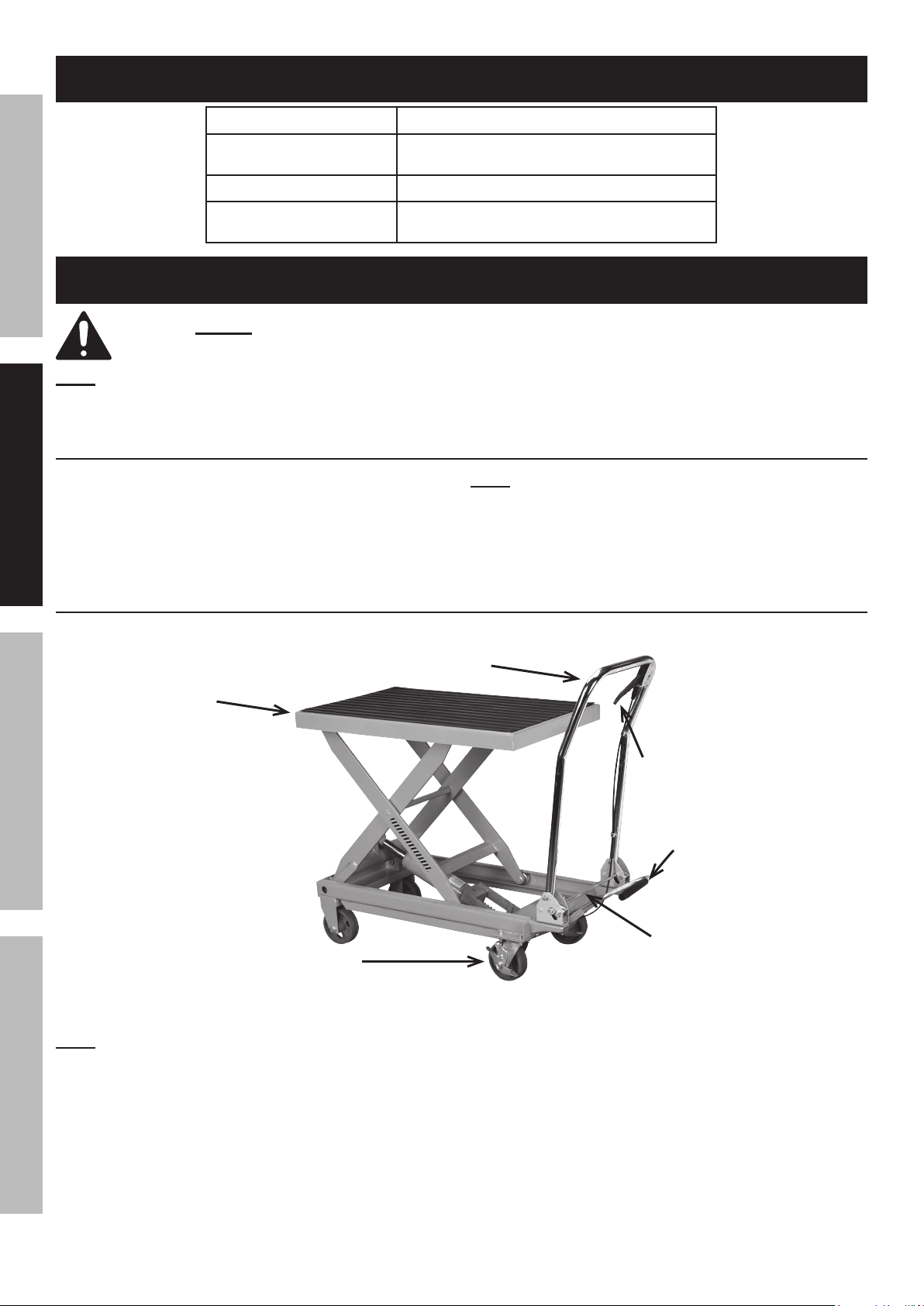
Functions
Table
Note: The Handle may be released and
folded back down by pressing down the Locking Bar.
3. Install the Pump Lever/Foot Pedal assembly into the
Connecting Rod and secure in place using the Bolt.
Handle
Control Lever
Pump Lever/
Foot Pedal
Locking Bar
Locking Swivel Caster
Figure A
Note: The Control Lever controls the operation of the Hydraulic Ram unit.
To lower the Ram and Table, squeeze the Control Lever.
When the Control Lever is released, the Ram and Table movement will stop and the table will remain stationary.
Page 4 For technical questions, please call 1-800-444-3353. Item 60438
 Loading...