

Harbor Freight Tools 60391 Product manual

Specifications
Weight Capacity 2000 lb.
Tilt
48 ° forward, 13° back,
12° side
This is the safety alert symbol. It is used to alert you to potential personal injury hazards.
Maximum Height 34-3/4"
Minimum Height 10-3/8"
WARNING SYMBOLS AND DEFINITIONS
Obey all safety messages that follow this symbol to avoid possible injury or death.
Indicates a hazardous situation which, if not avoided,
will result in death or serious injury.
Indicates a hazardous situation which, if not avoided,
could result in death or serious injury.
Indicates a hazardous situation which, if not avoided,
could result in minor or moderate injury.
Addresses practices not related to personal injury.
IMPORTANT SAFETY INFORMATION
Read all safety warnings and instructions.
Save all warnings and instructions for future reference.
Failure to heed these markings may result in personal injury and/or property damage:
1. Study, understand, and follow all instructions
before operating this device.
2. Do not exceed 2000 lb. rated capacity.
3. Use only on hard, level surfaces.
4. Adequately support the vehicle
before starting repairs.
5. Use of this product is limited to the removal,
installation, and transportation in the lowered position,
of transmissions, transfer cases, and transaxles.
6. Do not adjust safety valve.
7. Wear ANSI-approved safety goggles and
heavy-duty work gloves during use.
8. Keep clear of load while lifting and lowering.
9. Lower load slowly.
10. Do not use for aircraft purposes.
11. Inspect before every use;
do not use if parts loose or damaged.
12. Do not alter the jack or use attachments and/or
adapters that are not supplied by the manufacturer.
13. The warnings, precautions, and instructions
discussed in this manual cannot cover all
possible conditions and situations that may occur.
The operator must understand that common sense
and caution are factors, which cannot be built into
this product, but must be supplied by the operator.
14. The brass components of this product contain lead,
a chemical known to the State of California to cause
cancer, birth defects (or other reproductive harm).
(California Health & Safety Code § 25249.5, et seq.)
SAVE THESE INSTRUCTIONS.
Page 2 For technical questions, please call 1-800-444-3353. Item 60391
Setup
Read the ENTIRE IMPORTANT SAFETY INFORMATION section at the beginning of this
manual including all text under subheadings therein before set up or use of this product.
TO PREVENT SERIOUS INJURY:
Remove load from the jack before any procedure on this page.
Note: For additional information regarding the parts listed in the following pages,
refer to Parts Lists and Diagrams on page 6.
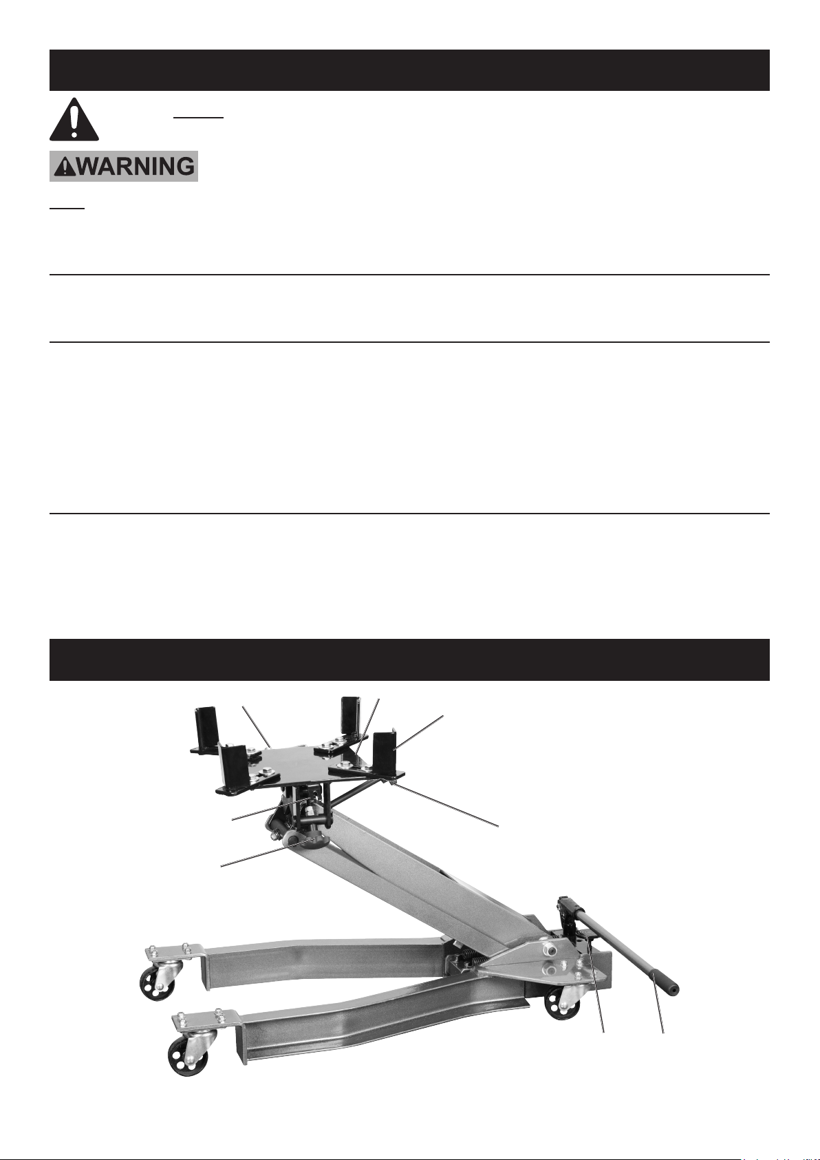
Assembly
Connect a Support (16) to each corner of the Saddle (12) using a Bolt (14) and Washer (15).
Checking/Filling Hydraulic Fluid
IMPORTANT! Before first use:
1. Remove the Oil Fill Plug from top of Hydraulic Ram.
2. Check hydraulic oil level and fill to 1/4"
below the fill port as needed.
Bleeding
1. Follow the Checking/Filling Hydraulic Fluid
instructions above.
2. Turn the Release Valve counterclockwise to open it.
3. Pump the Handle up and down quickly several
times to purge air from the system.
Functions
Chain
Saddle
3. Replace the Oil Fill Plug in top of Hydraulic Ram.
4. Thoroughly test the Jack for proper operation.
If it does not work properly, bleed air from its
hydraulic system as described in Bleeding, below.
4. Check hydraulic oil level and fill to
1/4" below the fill port as needed.
5. Replace the Oil Fill Plug and close the
Release Valve by turning it clockwise.
Support
tab
Side Tilt
Knob
Forward
Tilt Knob
Release
Valve
Handle
Page 3For technical questions, please call 1-800-444-3353.Item 60391
 Loading...