

Harbor Freight Tools 60307 Owner's Manual
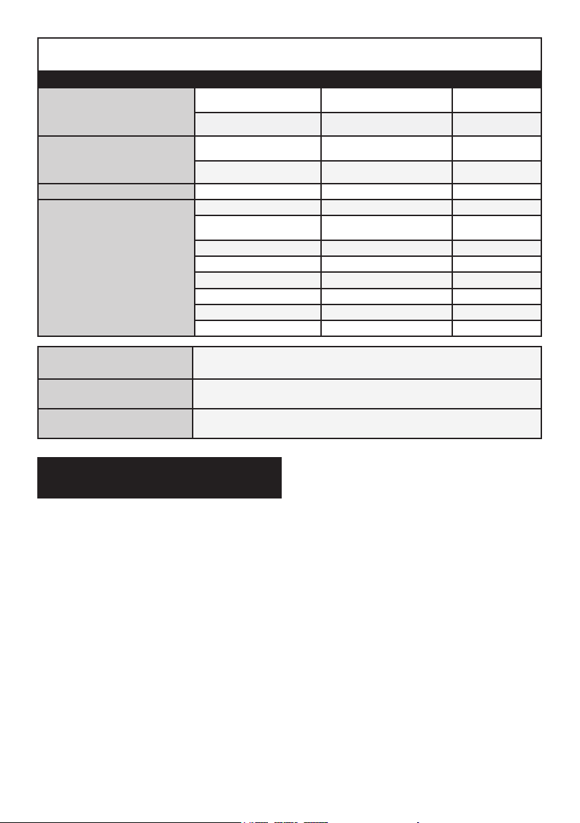
SPECIFICATIONS TABLE
Sizes Inner Diameter Outer Diameter Length
Receiving Cup
Installing Tube
Remover / Installer 3/4″ 1-7/16″ 1″
Receiving Tube
1-3/4″ 2-1/8″ 1/2″
1-13/16″ 2-1/4″ 7/16″
1-3/4″ 2″ 2-3/8″
1-3/4″ 2″ 3″
2″ 2-1/4″ 2″
2-1/4″ 2-1/2″ 1-1/2″
2-1/4″ 2-1/2″ 3/4″
2-1/4″ 2-1/2″ 2-3/4″
2-3/4″ 3″ 2-1/4″
2-7/16″ 2-3/4″ 2-1/4″
2-5/8″ 2-7/8″ 2-7/8″
2-3/16″ 2-7/16″ 3-3/16″
Applications
Most GM®, Ford®, and Dodge® 2 & 4 WD Pickups,
Vans, and SUV’s through 1997
Material Forged, heat treated and machined carbon steel
Screw Plug Size 7/8″ O.D. x 3″ Long
Important Safety Information
1. Keep work area clean and well lit.
Cluttered or dark areas invite accidents.
2. Keep children and bystanders away
while using this product. Distractions
can cause you to lose control.
3. Stay alert, watch what you are
doing and use common sense when
using this product. Do not use this
product while you are tired or under
the inuence of drugs, alcohol or
medication. A moment of inattention
while using this product may result
in serious personal injury.
4. Use safety equipment. Always wear
eye protection. Safety equipment
such as non‑skid safety shoes,
hard hat, or heavy duty work gloves
used for appropriate conditions
will reduce personal injuries.
5. Do not overreach. Keep proper
footing and balance at all times.
This enables better control of this
product in unexpected situations.
6. Dress properly. Do not wear loose
clothing or jewelry. Keep your hair,
clothing and gloves away from moving
parts. Loose clothes, jewelry or long
hair can be caught in moving parts.
7. Do not force this product. Use the
correct product for your application.
The correct product will do the
Page 2 For technical questions, please call 1-800-444-3353. Item 60307
job better and safer at the rate
for which it was designed.
8. Store this product out of the reach
of children and do not allow people
unfamiliar with the product or these
instructions to operate the product.
This product could be dangerous
in the hands of untrained users.
9. Maintain this product. Check for
misalignment or binding of parts,
breakage of parts and any other
condition that may affect the
product’s operation. If damaged,
have this product repaired before
use. Many accidents are caused
by poorly maintained equipment.
10. Use this product in accordance with
these instructions and in the manner
intended for this particular type of
product, taking into account the
working conditions and the work to
be performed. Use of this product for
operations different from those intended
could result in a hazardous situation.
11. Maintain labels and nameplates
on the Adapter Set. These carry
important safety information. If
unreadable or missing, contact Harbor
Freight Tools for a replacement.
12. Wear ANSI‑approved safety
goggles and heavy duty work
gloves when using this product.
13. Prior to servicing a vehicle, turn off
the vehicle’s engine and refer to
the vehicle manufacturer’s service
and repair manual for instructions
on how to safely secure the vehicle
in place with jacks, stands, etc.
14. The warnings, precautions, and
instructions discussed in this instruction
manual cannot cover all possible
conditions and situations that may
occur. It must be understood by the
operator that common sense and
caution are factors which cannot
be built into this product, but must
be supplied by the operator.
Operating Instructions
Read the ENTIRE IMPORTANT
SAFETY INFORMATION
section at the beginning of
this document including all
text under subheadings therein
before set up or use of
this product.
Attaching Plug Bolt to C-Frame
1. NOTE: This set is recommended for
use with Item 4065 4-Wheel Drive
Ball Joint Service Kit, which is also
available from Harbor Freight Tools.
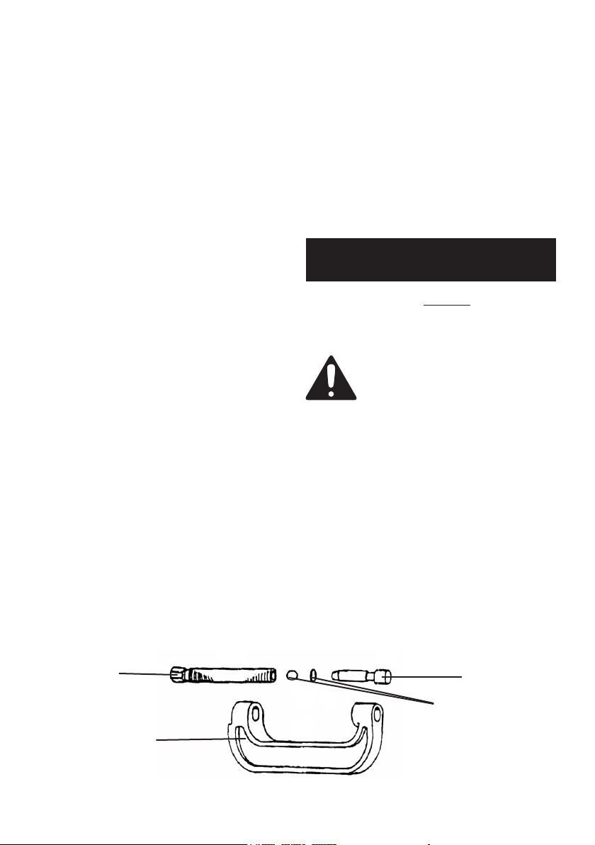
2. The illustration in Figure A below
depicts a disassembled C‑Frame, a tool
that is part of Item 4065 Service Kit.
3. To operate Master Ball Joint Adapter
Set, attach the Plug Bolt (part 14)
to the C‑Frame from Item 4065.
Forcing
Screw
(not included)
C‑Frame
(Part of Item
4065)
Plug Bolt (14)
Steel Ball / O-Ring
(not included)
Figure A
Page 3For technical questions, please call 1-800-444-3353.Item 60307
4. To do so, unscrew and remove
the Forcing Screw, Steel Ball,
and O-Ring from the C-Frame.
5. Make sure Steel Ball and O-Ring
remain inside the Forcing Screw. Then
insert Plug Bolt into Forcing Screw.
6. Screw threaded end of Forcing Screw,
with its Steel Ball, O-Ring, and
attached Plug Bolt back into
threaded end of C‑Frame toward
unthreaded hole of C‑Frame.
Removing a Ball Joint
1. NOTE: The following instructions apply
to most GM®, Ford®, and Dodge®
2 and 4 wheel drive pickups, vans, and
SUV’s through 1997 (see charts on
pages 6 through 9). The instructions
are intended to illustrate the process in
general terms, and NOT to be
specic to any one make/model vehicle.
A combination of Receiving Tubes
(parts 1-6 and 10-11), Receiving
Cups (parts 7 and 12), and
Installing Tubes (parts 8‑9), will be
necessary for different vehicles.
2. Remove all attaching
hardware from ball joint.
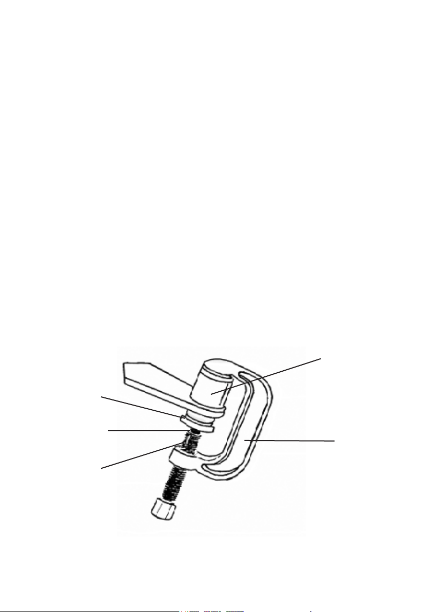
3. Mount Remover/Installer (13) on
Forcing Screw assembly so that
larger diameter portion of Remover/
Installer faces threaded hole of
C‑Frame, and smaller diameter
portion faces unthreaded side of
ball joint. See Figure B below.)
4. Mount proper size Receiver Tube
over threaded side of ball joint.
5. Align mounted Remover/Installer,
ball joint, and Receiver Tube to
allow removal of ball joint.
6. Using a wrench, turn Forcing Screw
assembly clockwise to remove ball joint.
Receiver Tube
(1‑6, 10‑11)
Remover /
Installer (13)
Plug Bolt (14)
C‑Frame
(Part of Item
Forcing
Screw
(not included)
Page 4 For technical questions, please call 1-800-444-3353. Item 60307
4065)
Figure B
 Loading...