

Page 1

Page 2
Table of Contents
Safety ......................................................... 3
Specifications ............................................. 4
Foundation.................................................. 4
SAFETY FRAME MAINTENANCEFOUNDATION
Frame ......................................................... 8
This is the safety alert symbol. It is used to alert you to potential personal injury hazards.
Maintenance .............................................. 13
Warranty .................................................... 14
Parts Lists .................................................. 14
WARNING SYMBOLS AND DEFINITIONS
Obey all safety messages that follow this symbol to avoid possible injury or death.
Indicates a hazardous situation which, if not avoided,
will result in death or serious injury.
Indicates a hazardous situation which, if not avoided,
could result in death or serious injury.
Indicates a hazardous situation which, if not avoided,
could result in minor or moderate injury.
Addresses practices not related to personal injury.
Page 2 For technical questions, please call 1-888-866-5797. Item 47712
Page 3

IMPORTANT SAFETY INFORMATION
The warnings, precautions, and instructions discussed in this manual cannot cover all possible conditions
and situations that may occur. The operator must understand that common sense and caution are factors,
which cannot be built into this product, but must be supplied by the operator.
Assembly / Installation Precautions
1. Assemble only according to these instructions.
Improper assembly can create hazards.
6. Do not assemble when tired or when under the
influence of alcohol, drugs or medication.
SAFETYFRAMEMAINTENANCE FOUNDATION
2. Wear ANSI-approved safety goggles and
heavy-duty work gloves during assembly.
3. This unit contains pieces with sharp edges.
The machined edges of the aluminum parts
and the ends of the panel clips may be sharp.
Handle all parts carefully.
4. Keep assembly area clean and well lit.
5. Keep bystanders out of the area during assembly.
Use / Service Precautions
1. This product is not a toy. Do not allow
children to play in or climb on this product.
Although this greenhouse does include some caps,
there are still some exposed sharp edges.
In addition, protective covers may fall off in time.
Children must be supervised if
allowed near the greenhouse.
2. SNOW/DEBRIS ACCUMULATION HAZARD.
The heavy weight of accumulated snow or other
debris can cause parts of this greenhouse to buckle
suddenly. Do not allow debris to accumulate on
top of the greenhouse. If snowfall is expected,
place additional supports (not provided) underneath
the Crown (35). NEVER enter a greenhouse
with accumulated debris on top.
7. Product capabilities apply to properly and
completely assembled product only.
8. Locate the Greenhouse on a flat, level, surface.
A concrete foundation is recommended
for a high-quality installation.
9. WARNING: The brass bushings inside the
Rollers of this product contain lead, a chemical
known to the State of California to cause
birth defects (or other reproductive harm).
(California Health & Safety Code § 25249.5, et seq.)
3. Use as intended only.
4. Inspect periodically; replace damaged parts
immediately and do not enter greenhouse
if parts are loose or damaged.
5. For your safety, service and maintenance should
be performed regularly by a qualified technician.
SAVE THESE INSTRUCTIONS.
Page 3For technical questions, please call 1-888-866-5797.Item 47712
Page 4

Specifications
Overall Dimensions 98-1/2″ L x 75-7/8″ W x 77″ H
SAFETY FRAME MAINTENANCEFOUNDATION
Window Dimensions 23″ L x 20″ W
Door Dimensions 64″ H x 24″ W x 1-1/4″ Thick
Materials
Aluminum Thickness 0.038″
Polycarbonate Sheet Thickness 0.165″
Aluminum Frame
Transparent Polycarbonate Sheets
Foundation Installation
Read the ENTIRE IMPORTANT SAFETY INFORMATION section at the beginning of this document
including all text under subheadings therein before set up or use of this product.
IMPORTANT–READ THE FOLLOWING CAREFULLY BEFORE PROCEEDING
• Prior to assembly, a proper foundation must be laid. The greenhouse must be properly
supported to help prevent property damage and injury in the event of strong winds or
inclement weather. Wind and ground conditions may vary from site to site, and may affect
the practicality and effectiveness of anchoring methods substantially. If you have any
doubt regarding the stability of the foundation you are to use, consult a professional.
• It is always your responsibility to ensure that the greenhouse is properly anchored.
Harbor Freight Tools cannot be held responsible for personal injury, damage to the greenhouse,
or other property damage that occurs as a result of improperly anchoring the greenhouse.
• Be certain to check with local authorities to obtain all required building permits
and to familiarize yourself with any building codes that may apply.
• Decide on a location for the greenhouse. The location should optimally be a
level, well-lit area that is sheltered from the wind. The door of the greenhouse
should not open towards the prevailing wind, if possible.
Page 4 For technical questions, please call 1-888-866-5797. Item 47712
Page 5

Concrete Anchor Foundation
75”
Concrete Anchor
Locations
981/2”
4”
1. This foundation will be assembled out of
4 x 4 treated lumber, hardware, and prefabricated
concrete anchors (none provided).
2. Assemble the 4 x 4 pieces in the
dimensions shown in the diagram below.
The wood will need to be trimmed to fit.
Make certain that the assembly is square and level.
The diagonal dimensions, from outside corner
to outside corner, should be 1233/4″ each.
3. Securely assemble the frame together
using proper hardware.
4. Dig a hole for each of the concrete anchors in
the positions shown. The hole should be slightly
oversized and should be deep enough so that the
frame will rest almost on the ground when installed.
5. Carefully place the anchors in the holes,
and place the frame on the anchors.
Use a level on the frame to make sure that
the anchors are sunk to the proper depth.
If any anchors need to be raised, partially fill the
hole under the anchor with sand or gravel.
6. Once the frame is level, secure it to the anchors.
Fill up the holes the rest of the way with
the earth you removed previously.
7. Optional: For convenience you may fill the
frame at this point with a proper fill material,
such as gravel (not included).
8. There are four Floor Plates to position on
the foundation; the Front Floor Plate (17),
the Rear Floor Plate (16), and
two Side Floor Plates (34).
(See Figure G on page 8.)
SAFETYFRAMEMAINTENANCE FOUNDATION
Figure A: Wood Frame Dimensions
9. Match the length of each of the
four Floor Plates (16, 17, 34) with the appropriate
length of each edge of the base.
Place the Front Floor Plate (17) on
the side that the door will face.
NOTE: Position the four Floor Plates (16, 17, 34)
with their outer edges overhanging the outer edges
of the frame, as shown below. Do not secure
the Floor Plates to the Frame at this time.
Figure B: Concrete Anchor Foundation - Cross Section
Page 5For technical questions, please call 1-888-866-5797.Item 47712
Page 6
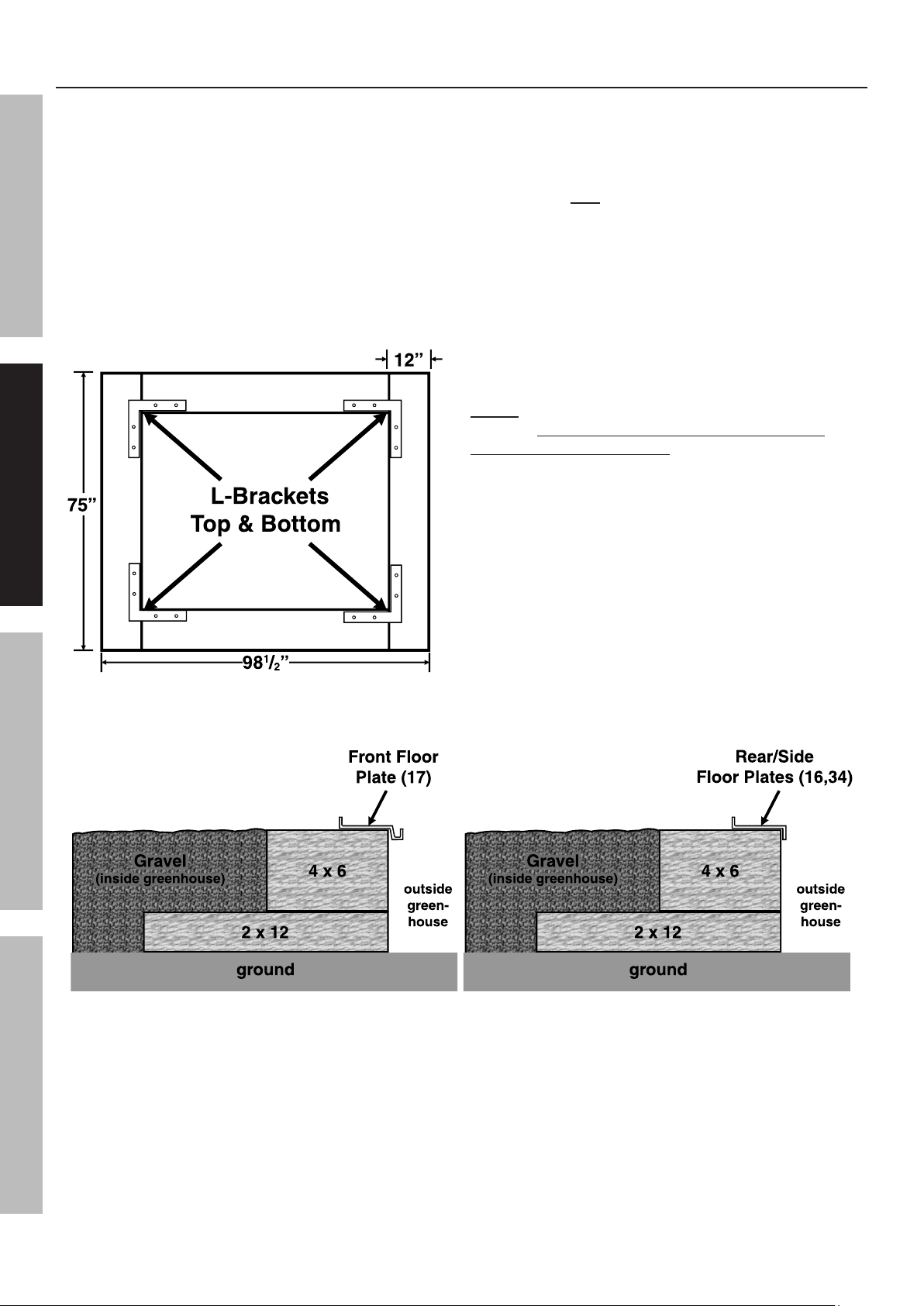
Treated Wood Base Foundation
75”
981/2”
12”
L-Brackets
Top & Bottom
4 x 6
2 x 12
Front Floor
Plate (17)
ground
outside
green-
house
Gravel
(inside greenhouse)
4 x 6
2 x 12
Rear/Side
Floor Plates (16,34)
ground
outside
green-
house
Gravel
(inside greenhouse)
1. The wood base will be assembled out of 4 x 6
and 2 x 12 treated lumber, hardware (including
galvanized lag bolts/deck screws), and
SAFETY FRAME MAINTENANCEFOUNDATION
fill material, such as gravel (none provided).
2. Assemble the 2 x 12 pieces in the dimensions
shown in the diagram below. The wood will
need to be trimmed to fit. Make certain that the
assembly is square and level. The diagonal
dimensions, from outside corner to outside corner,
should be 1233/4″ each. Also use a level to
ensure that the base is even. If needed, fill under
sections of the base to make sure it is level.
3. Assemble the 4 x 6 pieces on top of the
base you just assembled, as shown in the
cross section below. Fill the base with the
fill material up to the top of the 4 x 6's.
4. There are four Floor Plates to position on
the foundation; the Front Floor Plate (17),
the Rear Floor Plate (16),
and two Side Floor Plates (34).
(See Figure G on page 8.)
5. Match the length of each of the
four Floor Plates (16, 17, 34) with the appropriate
length of each edge of the base.
Place the Front Floor Plate (17) on
the side that the door will face.
NOTE: Position the four Floor Plates (16, 17, 34)
with their outer edges overhanging the outer edges
of the base, as shown below. Do not secure
the Floor Plates to the Base at this time.
Page 6 For technical questions, please call 1-888-866-5797. Item 47712
Figure C: Wood Base Dimensions
Figure D: Wood Base Cross Section
Page 7
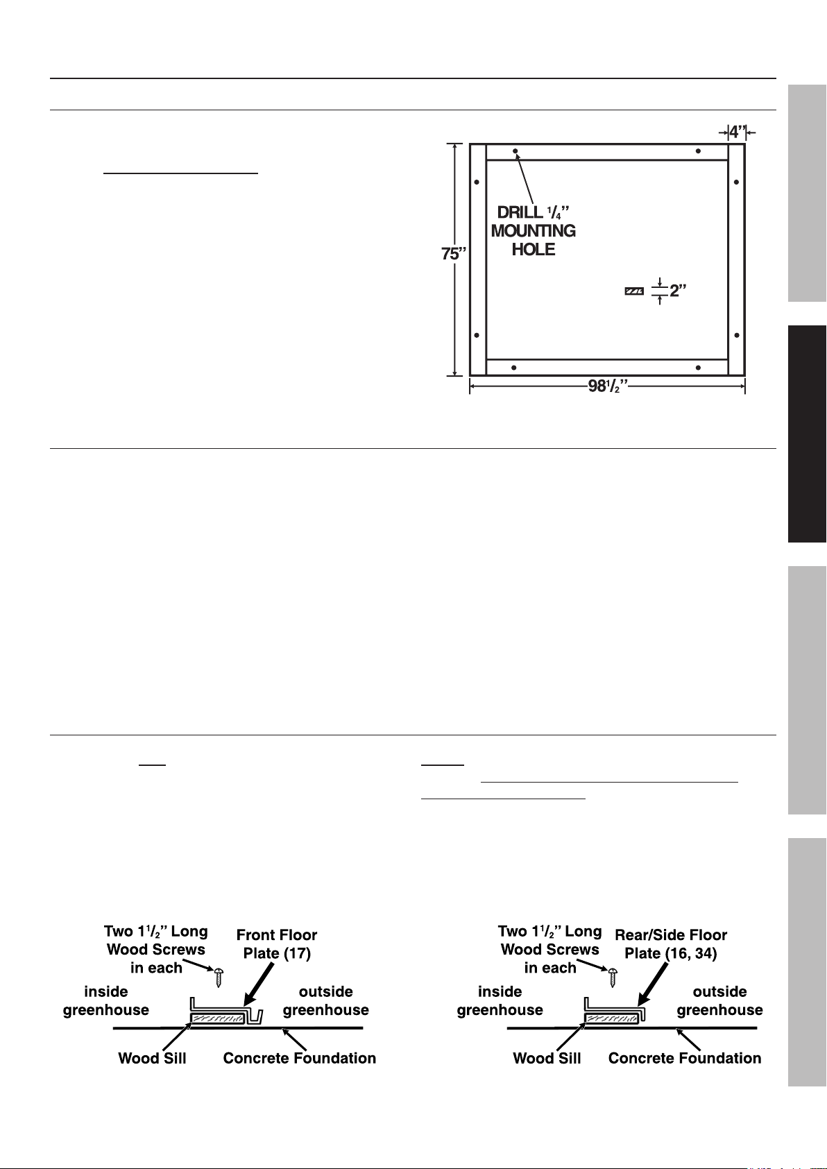
Concrete Slab Foundation
Wood Sill
Concrete Foundation
outside
greenhouse
inside
greenhouse
Two 11/2” Long
Wood Screws
in each
Front Floor
Plate (17)
Wood Sill
Concrete Foundation
outside
greenhouse
inside
greenhouse
Two 11/2” Long
Wood Screws
in each
Rear/Side Floor
Plate (16, 34)
Constructing a Wooden Sill
1. The greenhouse must be attached to a
wood sill, and not directly to a concrete slab.
Use four4″wideby2″thick wooden boards
(not provided) to construct a sill.
2. Cut the four boards to the proper dimensions shown.
3. Place the four boards to form a
rectangle on a level floor surface.
4. Exact dimensions may vary slightly.
Lay the base components out together,
square them, then take actual measurements.
Both diagonal measurements, from outer corner
to outer corner, should be 1233/4″ each.
5. Secure the boards together at the corners
using wood screws (not provided).
Attaching the Sill to the Concrete Slab
1. A concrete slab foundation upon which the
Greenhouse will be positioned will help to
ensure stability. The slab can be slightly oversize.
2. Drill two 1/4″ holes through each of the four boards.
3. Next, use the two predrilled holes in each board as
a template to mark the points where eight anchor
holes will be drilled in the concrete floor.
Then, temporarily remove the sill.
SAFETYFRAMEMAINTENANCE FOUNDATION
Figure E: Wood Sill Dimensions
5. Move the four boards back to the concrete floor
surface, and align all eight predrilled holes in the four
boards with the eight previously drilled anchor holes.
If necessary, level the boards by inserting stainless
steel shims (sold separately) between the boards and
the concrete floor. Do not exceed 1/2″ shim thickness.
6. Secure the four boards to the concrete floor,
using eight 1/4″ diameter anchor bolts of appropriate
length, eight washers, and eight nuts (not provided).
4. Where previously marked on the
concrete floor, drill all eight 1/4″ diameter,
minimum 4″ deep, anchor holes.
Blow the concrete dust out from the drilled holes.
Positioning the Floor Plates on the Sill
1. There are four Floor Plates to
attach to the sill; the Front Floor Plate (17),
the Rear Floor Plate (16), and two Side Floor
Plates (34).(See Figure G on page 8.)
2. Match the length of each of the
four Floor Plates (16, 17, 34) with the appropriate
length of each of the four foundation boards.
Place the Front Floor Plate (17) on
the side that the door will face.
NOTE: Position the four Floor Plates (16, 17, 34)
with their outer edges overhanging the outer edges
of the sill, as shown below. Do not secure
the Floor Plates to the Sill at this time.
Figure F: Sill Cross Section
Page 7For technical questions, please call 1-888-866-5797.Item 47712
Page 8

Frame Assembly
Read the ENTIRE IMPORTANT SAFETY INFORMATION section at the beginning of this document
including all text under subheadings therein before set up or use of this product.
SAFETY FRAME MAINTENANCEFOUNDATION
• Unlessnotedotherwise,attachallframepartsusingtheBolts(43)andNuts(52)provided.
Tighten nuts only about 1/4 turn past finger tight; be careful not to overtighten.
• Lay out all parts by number prior to assembly.
• Use an assistant or an appropriate support (not included) to keep the partially assembled parts upright
during assembly. Use two assistants to assemble the Crown pieces to the rest of the frame.
• Assemble on a clear, calm day. Wind will damage the Greenhouse and make assembly difficult.
Assembling the Frame Edges
Side
Ceiling
Plate (36)
1. There are four Corner Studs (1) to be
attached to the four Floor Plates (16, 17, 34).
Attach one Corner Stud (1) on the outside of
each corner. Attach an End Cap (47) to the
top outer corner of each Corner Stud (1).
(Rear)
(Left)
Figure G: Frame Edges
2. Once the four Corner Studs (1) are connected to the
Floor Plates (16, 17, 34), drill three pilot holes 11/2″
through each Floor Plate and into the underlying
wood sill or base. Make sure not to drill into any of
the hardware used earlier. Then, secure the Floor
Plates to the foundation, using three 11/2″ long wood
screws (sold separately) for each Floor Plate.
(Right)
(Front)
Page 8 For technical questions, please call 1-888-866-5797. Item 47712
Page 9

3. Attach a Side Ceiling Plate (36) flat against the
inside of two Corner Studs (1). Make sure that the
gutter on the Side Ceiling Plate is oriented correctly,
see Figure G inset. At this point, the completed
section of the frame will likely need support.
4. Attach the Rear Ceiling Plate (21) to
the inside of the two Corner Studs (1)
that are over the Rear Floor Plate (16).
Point the Rear Ceiling Plate’s flange inward.
(See Figure G.)
5. Attach the Left and Right Rear Studs (8,9) to
the outside of the Rear Floor Plate (16) and
Rear Ceiling Plate (21). Orient them so that
the ends slope upwards toward the middle
of the greenhouse. (See Figure G.)
Note: The heads of the Bolts (43) fit
into the slot on the back of the Stud,
holding the Bolts in place during assembly.
6. Attach the remaining Side Ceiling Plate (36)
along the other side, flat against the inside of the
Corner Studs (1), with the gutter oriented properly.
8. Attach the Front Crown Beams (2,3)
to the Crown (35) in the same fashion
as the Rear Crown Beams.
9. Attach an End Cap (47) onto the outer end
of each Crown Beam (2-5). Cover the gaps
between the Crown Beams (between 2-3 & 4-5)
with a Peak Cap (54) in each.
10. Attach a Corner Bracket (13) at the top of
each Corner Stud (1) so that the bracket faces
upwards, see diagram below. At the Studs that the
Rear Ceiling Plate (21) is connected to, the Bolt (43)
holding the Ceiling Plate on will need to be removed
temporarily while the Bracket is installed between
the Rear Ceiling Plate and the Corner Stud.
SAFETYFRAMEMAINTENANCE FOUNDATION
7. At the side of the Greenhouse: Attach the
Rear Right and Rear Left Crown Beams (4,5)
to the outside of the Crown (35) with the angled
edges towards the top. See diagram below,
viewed from under the Crown, facing back.
11. With two assistants, lift the Crown Assembly
and place the Crown Beams (2-5) on
top of the Corner Brackets (13).
12. Attach the remaining Side Ceiling Plate (36)
flat against the inside of two Corner Studs (1).
Once again, verify that the gutter on the Side Ceiling
Plate is oriented correctly, see Figure C inset.
At this point, the unit should be more stable.
13. Place the Gutter Caps (48) onto the ends of the
Side Ceiling Plates (36) oriented with a gap in the
bottom to allow water to drain out of the gutters.
Page 9For technical questions, please call 1-888-866-5797.Item 47712
Page 10
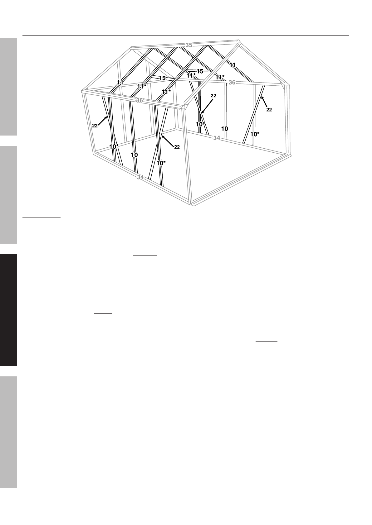
Assembling the Side and Roof Frames
36
36
35
34
34
10*
10
10*
10*
10
10*
11
11*
11*
11
11*
11*
15
15
22
22
22
22
SAFETY FRAME MAINTENANCEFOUNDATION
IMPORTANT: Assemble all parts marked with an asterisk (*) above with an extra Bolt (43) in the slot.
Figure H: Stud and Brace Locations
1. Attach three Side Vertical Studs (10) to a
Side Floor Plate (34) and a Side Ceiling Plate (36).
Make sure that they are assembled vertically, there
are extra holes for the diagonals. Also, include
extra Bolts in the Studs noted above with asterisks.
Repeat this Step for the remaining Side Floor Plate
and Side Ceiling Plate. (See Figure H.)
2. Attach two Side Diagonal Braces (22) to a Side
Floor Plate (34) and a Side Ceiling Plate (36)
with the flange facing inward. Use the extra
Bolt (43), noted in the caption above, to secure
the center portion of each Diagonal Brace (22).
Repeat this Step for the remaining Side Floor Plate
and Side Ceiling Plate. (See Figure H.)
3. Attach the six Roof Studs (11) between the
Crown (35) and the two Side Ceiling Plates (36).
Include extra Bolts in the four Studs noted
with an asterisk above. (See Figure H.)
4. Slide the Window Support Beams (15) onto the four
Roof Studs (11) that you included extra bolts in,
with the predrilled holes on the underside and
the flat side facing the Crown (35). Use the extra
Bolts (43), to secure the Beam loosely in place.
It will need adjustment when installing the window.
5. Using two Window Screws (45), attach each
Window Stop (18) to the Window Support Beam (15)
with its tab pointing towards the Crown (35).
Both should be on the underside of their
Window Support Beam, inside the greenhouse.
Page 10 For technical questions, please call 1-888-866-5797. Item 47712
Page 11

Assembling the Front Frame
3
17
1
1
13
13
2
2
39
38
19
19
23
23
23
25
25
14
12
7
6
6
(partially
behind #14)
SAFETYFRAMEMAINTENANCE FOUNDATION
1. Attach the Right and Left Doorway Studs (6,7)
to the Front Right and Left Crown Beams (2,3)
and the Front Floor Plate (17) as shown above.
The cutoff corners on the Studs should be at the
top and should face away from the center of the
greenhouse. (See Figure I and right inset.)
2. Attach the Front Diagonal Stud (25) to
the lower Bolt on the Corner Bracket (13)
and bottom of the Front Floor Plate (17).
The flange should face inside. (See Figure I.)
3. Attach the other Front Diagonal Stud (25)
in the same way on the opposite side.
4. Attach a Front Ceiling Plate (23) to the
Bolt (43) on the Corner Bracket (13) that is
right above the Diagonal-Bracket connection.
Connect the other end to the Left Doorway Stud (7).
Attach the remaining Front Ceiling Plate (23)
between the Corner Bracket (13) and Right
Doorway Stud (6). (See Figure I.)
Figure I: Front Frame
5. Attach the Top Doorway Beam (12) between
the Front Right and Left Crown Beams (2,3).
Turn it so that the nicked corners are facing up
and the two remaining holes are facing the outside
to allow the Door Rail (14) to be attached.
6. Attach the Vertical Extender (19) to the
Front Left Crown Beam (3) using the
Long Door Support Bolt (38) and Nut (52), with the
Door Support Spacer (39) between the Extender
and the Stud. (See Figure I, left inset.)
7. Place three Bolts (43) in the Slot at the back
of the Door Rail (14). Attach the Rail to the
Top Doorway Beam (12) and the free end
of the Vertical Extender (19), with the
rounded side up. (See Figure I.)
Page 11For technical questions, please call 1-888-866-5797.Item 47712
Page 12

Assembling/Installing the Door
The door is assembled using the Door Screws (44).
The Screws thread directly into the rounded portions of the parts in the center of the door.
1. Place the Left Door Frame (20) with the
SAFETY FRAME MAINTENANCEFOUNDATION
Rubber Seal (42) side down.
Attach the Center Door
Frames (26) to the Left
Door Frame (20).
Assemble them with the
rounded portion facing the front,
as shown to the right.
These parts are also marked
with an arrow that needs to point towards
the top of the door.
2. Attach the Right Door Frame (28) to the
Center Door Frames (26) in the same way.
3. Attach the Door Top Frame (24) to the Left and Right
Door Frames (20 and 28).
Turn them so that the rounded
portion faces the front and that
the flange where the pane will sit
faces the center of the door,
see the diagram to the right.
4. Using two Bolts (43) and two Nuts (52), attach
the Door Slider (31) to the Door Top Frame (24)
with the rollers on the top of the door.
5. Insert a Door Bottom Slider (40) into each end of the
Bottom Door Frame (27).
Install the Sliders correctly, with
the gap facing the back of the
door, see diagram to the right.
Attach the Bottom Door
Frame (27) to the Left and Right
Door Frames (20,28) using
two Screws (44) on each side –
the top one into the Bottom Door Frame (27) and
the bottom one into the Door Bottom Slider (40).
6. Raise the assembled Door up and insert the first
roller of its Door Slider (31) onto the Door Rail (14).
Carefully align the first Bottom
Door Slider (40) over the edge of
the Front Floor Plate (17),
see illustration to the right.
Carefully slide the door over and
align the other top Roller and
bottom Slider as was
done earlier.
7. Once the door is installed, install a Bolt (43)
and Nut (52) into the hole on each side of the
Door Rail (14) to prevent the door from sliding
off its rail. Attach the Right and Left Rail End
Caps (49,50) onto the ends of the Door Rail.
Assembling/Installing the Windows
Follow the steps below for each of the two windows.
1. Attach the Side Window Frames (30)
to the Top Window Frame (33),
as shown to the right.
2. Insert Bolts (43) into the
holes at the bottom of the
Side Window Frames (30), so that the threads
stick out the bottom of the window.
3. Remove the protective film from both sides
of the Window Pane (5A). Slide the Window
Pane (5A) into the three sided frame.
4. Slide the Bottom Window Frame (32) onto the two
Bolts (43) and the Window Pane (5A). Secure it in
place with Nuts (52). If needed, apply some pressure
to the heads of the Bolts through the Window
Pane to allow the Nuts to thread on properly.
5. Attach the Window Brace (51) to the Bottom
Window Frame (32) using two Window Screws (45).
The holes on the Window Brace (51)
should face away from the window.
6. Slide the top edge of the Top Window Frame (33) into
the slot at the top of
the Crown (35),
see illustration
to the right.
The window should
be aligned with the
Window Brace (51)
on the bottom.
Slide the window
into place over one
Window Support
Beam (15).
Gradually lower it
into place.
7. Loosen the Nuts (52) holding the
Window Support Beam (15) in place and slide the
Window Support Beam (15) up to touch the window.
Secure it into place.
Top Window
Frame (33)
(View from end of Crown.)
Crown
(35)
Page 12 For technical questions, please call 1-888-866-5797. Item 47712
Page 13

Transparent Panel Installation
A
Transparent
Panel
Frame
Member
Panel
Clip (46)
B C
2A/4A
2A 2A
36
1. Panel Clips (46) are used to secure the
Transparent Panels in place on the Greenhouse.
(See Parts List A.)
Note: Remove the protective film from both sides
of all panels as they are installed.
After removing the protective film from the
Door Center Panel (7A), stick the warning label to it.
Install the Door Center Panel so that the warning label
is easily readable from outside the greenhouse.
2. The Roof Panels (2A) and the
Roof Window Panel (4A) will need to be placed as
shown in the illustrations below. The bottom edges
of these panels need to align above the gutter to
direct rain off the greenhouse. The top edges of
these panels need to be placed up under the edge of
the Crown (35) or the Window Support Beam (15).
35
32
4A
SAFETYFRAMEMAINTENANCE FOUNDATION
15
3. One at a time, place each Transparent Panel
(1A through 9A) in its proper location on
the Ceiling and Frame of the Greenhouse.
Then, use Panel Clips (46) in the quantity
and location of shown in Parts List A
to secure the Transparent Panel in place.
4. To attach Panel Clips,
see illustration and instructions below:
A) Place the two loose ends of the Clip
into the groove in the frame
B) Swing the center portion of the
Clip up against the Panel
C) Two edges of the Clip swing under
the edge of the panel and the center
edge holds the panel in place.
Be careful, Panel Clip (46) ends may be sharp and may spring back!
Use and Maintenance
1. BEFORE EACH USE, inspect the general condition
of the Greenhouse. Check for loose screws,
misalignment or binding of moving parts, cracked
or broken parts, and any other condition that
may affect the safe operation of the Greenhouse.
If a problem occurs with the Greenhouse, have it
corrected before further use.
Do not use damaged equipment.
2. TO CLEAN: Wipe with a damp cloth, using a mild
detergent.
Do not use cleaners that are combustible,
corrosive, or not compatible with aluminum.
3. WHEN STORING: Keep the Greenhouse
in a box and in a clean, dry location.
Page 13For technical questions, please call 1-888-866-5797.Item 47712
Page 14

Limited 90 Day Warranty
Harbor Freight Tools Co. makes every effort to assure that its products meet high quality and durability standards,
and warrants to the original purchaser that this product is free from defects in materials and workmanship for the
period of 90 days from the date of purchase. This warranty does not apply to damage due directly or indirectly,
SAFETY FRAME MAINTENANCEFOUNDATION
to misuse, abuse, negligence or accidents, repairs or alterations outside our facilities, criminal activity, improper
installation, normal wear and tear, or to lack of maintenance. We shall in no event be liable for death, injuries
to persons or property, or for incidental, contingent, special or consequential damages arising from the use of
our product. Some states do not allow the exclusion or limitation of incidental or consequential damages, so the
above limitation of exclusion may not apply to you. THIS WARRANTY IS EXPRESSLY IN LIEU OF ALL OTHER
WARRANTIES, EXPRESS OR IMPLIED, INCLUDING THE WARRANTIES OF MERCHANTABILITY AND FITNESS.
To take advantage of this warranty, the product or part must be returned to us with transportation charges
prepaid. Proof of purchase date and an explanation of the complaint must accompany the merchandise.
If our inspection verifies the defect, we will either repair or replace the product at our election or we may
elect to refund the purchase price if we cannot readily and quickly provide you with a replacement. We will
return repaired products at our expense, but if we determine there is no defect, or that the defect resulted
from causes not within the scope of our warranty, then you must bear the cost of returning the product.
This warranty gives you specific legal rights and you may also have other rights which vary from state to state.
PLEASE READ THE FOLLOWING CAREFULLY
THE MANUFACTURER AND/OR DISTRIBUTOR HAS PROVIDED THE PARTS LISTS IN THIS DOCUMENT
AS A REFERENCE TOOL ONLY. NEITHER THE MANUFACTURER OR DISTRIBUTOR MAKES ANY
REPRESENTATION OR WARRANTY OF ANY KIND TO THE BUYER THAT HE OR SHE IS QUALIFIED TO
MAKE ANY REPAIRS TO THE PRODUCT, OR THAT HE OR SHE IS QUALIFIED TO REPLACE ANY PARTS
OF THE PRODUCT. IN FACT, THE MANUFACTURER AND/OR DISTRIBUTOR EXPRESSLY STATES
THAT ALL REPAIRS AND PARTS REPLACEMENTS SHOULD BE UNDERTAKEN BY CERTIFIED AND
LICENSED TECHNICIANS, AND NOT BY THE BUYER. THE BUYER ASSUMES ALL RISK AND LIABILITY
ARISING OUT OF HIS OR HER REPAIRS TO THE ORIGINAL PRODUCT OR REPLACEMENT PARTS
THERETO, OR ARISING OUT OF HIS OR HER INSTALLATION OF REPLACEMENT PARTS THERETO.
Parts Lists
Part Description Qty
1 Corner Stud
2 Front Rt. Crown Beam 1
3 Front Lt. Crown Beam 1
4 Rear Rt. Crown Beam 1
5 Rear Lt. Crown Beam 1
6 Right Doorway Stud 1
7 Left Doorway Stud 1
8 Left Rear Stud 1
9 Right Rear Stud 1
10 Side Stud 6
Part Description Qty
4
12 Top Doorway Beam
13 Corner Bracket
14 Door Rail
15 Window Support Beam
16 Rear Floor Plate
17 Front Floor Plate 1
1
4
1
2
1
11 Roof Stud
Page 14 For technical questions, please call 1-888-866-5797. Item 47712
6
18 Window Stop
2
Page 15

Part Description Qty
Part Description Qty
19 Door Slide Support
20 Left Door Frame 1
28 Right Door Frame 1
21 Rear Ceiling Plate 1
22 Side Diagonal Brace 4
23 Front Ceiling Plate 2
24 Top Door Frame
25 Front Diagonal Brace 2
1
1
38 Long Door Support Bolt
39 Door Support Spacer 1
40 Door Bottom Slider 2
41 Spanner Wrench 2
42 Rubber Seal 2
43 Bolt 105
44 Door Screw 16
1
SAFETYFRAMEMAINTENANCE FOUNDATION
26 Center Door Frame 2
27 Bottom Door Frame 1
30 Side Window Frame 4
31 Door Slider 1
32 Bottom Window Frame 2
33 Top Window Frame 2
34 Side Floor Plate 2
45 Window Screw 8
46 Panel Clip 144
47 End Cap 8
48 Gutter End Cap 4
49 Right Rail End Cap 1
50 Left Rail End Cap 1
51 Window Brace
2
35 Crown 1
36 Side Ceiling Plate 2
37 Top Roller Screw 2
52 Nut
53 Roller 4
54 Peak Cap 2
106
Page 15For technical questions, please call 1-888-866-5797.Item 47712
Page 16

Parts List A- Panels
Part Description Size Qty
1A Side Panel 23.81″ x 47.63″ 8
2A Roof Panel 23.81″ x 44.48″ 6
Front/Rear
3A
Panel
Roof Window
4A
Panel
5A Window Pane 23.62″ x 21.45″ 2
23.81″ x 65.35″ 4
23.81″ x 23.22″ 2
8A
9A
3A 3A
7A
Panel
Clip (46)
location
Part Description Size Qty
Rear Center
6A
Panel
Door Center
7A
Panel
Top Center
8A
Panel
9A Door Panel 23.81″ x 23.70″ 2
23.81″ x 73.70″ 1
23.81″ x 9.44″ 1
24.21″ x 9.13″ 1
2A
5A
2A
2A
4A
9A
warning
label
location
Record Serial Number Here:
Note: If product has no serial number, record
month and year of purchase instead.
3A
6A
1A
1A
3A
Note: Some parts are listed and shown for
illustration purposes only, and are not available
individually as replacement parts.
1A
1A
3491 Mission Oaks Blvd. • PO Box 6009 • Camarillo, CA 93011 • 1-888-866-5797
Page 17

3491 Mission Oaks Blvd. • PO Box 6009 • Camarillo, CA 93011 • 1-888-866-5797
por separado como piezas de repuesto.
de ilustración únicamente y no están disponibles
Nota: Algunas piezas se detallan y muestran a modo
tome nota del mes y el año de la compra.
Nota: Si el producto no posee número de serie,
Anote el número de serie del producto aquí:
1A
1A
2A
2A
1A
24,21″ x 9,13″ 1
23,81″ x 9,44″ 1
23,81″ x 73,70″ 1
4A
1A
5A
3A
6A
2A
9A Panel de la puerta 23,81″ x 23,70″ 2
superior
8A
Panel central
puerta
7A
Panel central de la
trasero
6A
Panel central
advertencia
la etiqueta de
ubicación de
9A
3A
7A
3A 3A
9A
paneles (46)
ganchos de los
Ubicación de los
23,81″ x 23,22″ 2
23,81″ x 65,35″ 4
Pieza Descripción Tamaño Cant.
8A
ventana del techo
Panel de la
trasero
Panel frontal/
5A Panel de la ventana 23,62″ x 21,45″ 2
4A
3A
2A Panel del techo 23,81″ x 44,48″ 6
1A Panel lateral 23,81″ x 47,63″ 8
Pieza Descripción Tamaño Cant.
Lista de piezas A - Paneles
Page 18

Artículo 47712
Si desea realizar preguntas técnicas, llame al 1-888-866-5797.
Página 15
2
2
1
1
4
54 Tapa de pico
53 Rodillo 4
52 Tuerca 106
51 Tirante de la ventana
riel izquierdo
50
Tapa del extremo del
riel derecho
49
Tapa del extremo del
canaleta
48
Tapa del extremo de la
2
2
2
2
2
1
perior
37
Tornillo del rodillo su-
36 Placa lateral del techo
35 Corona 1
34 Placa lateral del piso
ventana
33
Marco superior de la
ventana
32
Marco inferior de la
de la puerta
31
Guía de deslizamiento
ventana
47 Tapa del extremo 8
46 Gancho del panel 144
45 Tornillo de la ventana 8
44 Tornillo de la puerta 16
43 Perno 105
42 Junta de caucho 2
41 Llave de gancho 2
4
1
2
2
1
30
Marco lateral de la
puerta
27
Marco inferior de la
puerta
26
Marco central de la
25 Tirante frontal diagonal
la puerta
24
Marco superior de
23 Placa frontal del techo 2
22 Tirante lateral diagonal 4
SEGURIDADBASTIDORMANTENIMIENTO CIMIENTO
puerta deslizante
2
1
1
40
Parte inferior de la
de la puerta
39
Espaciador de soporte
de la puerta
38
Perno largo de soporte
Pieza Descripción Cant.
1
1
1
21 Placa trasera del techo 1
la puerta
28
Marco derecho de
la puerta
20
Marco izquierdo de
miento de la puerta
19
Soporte de desliza-
Pieza Descripción Cant.
Page 19

Página 14
Si desea realizar preguntas técnicas, llame al 1-888-866-5797.
Artículo 47712
18 Tope de la ventana 2
17 Placa frontal del piso 1
1
16 Placa trasera del piso 1
1
ventana
2
1
15
Viga de soporte de la
14 Riel de la puerta 1
13 Soporte de esquina 4
puerta
12
Viga superior de la
Pieza Descripción Cant.
1
1
1
1
1
1
11 Montante del techo 6
10 Montante lateral 6
derecho
9
Montante trasero
izquierdo
8
Montante trasero
la puerta
7
Montante izquierdo de
puerta
6
Montante derecho de la
de la corona
5
Viga trasera izquierda
la corona
4
Viga trasera derecha de
izquierda de la corona
3
Viga delantera
de la corona
2
Viga delantera derecha
1 Montante de esquina 4
Pieza Descripción Cant.
Listas de piezas
INSTALACIÓN DE PIEZAS DE REEMPLAZO QUE REALICE.
DEL PRODUCTO ORIGINAL O DE LAS PIEZAS QUE REEMPLACE, O QUE PUEDAN DERIVARSE DE LA
ASUME TODOS LOS RIESGOS Y RESPONSABILIDADES QUE PUEDAN DERIVARSE DE LAS REPARACIONES
POR TÉCNICOS DIPLOMADOS Y CERTIFICADOS, Y NO POR EL/LA COMPRADOR(A). EL/LA COMPRADOR(A)
CONSTANCIA DE QUE TODAS LAS REPARACIONES Y REEMPLAZOS DE PIEZAS DEBEN SER EFECTUADOS
NINGUNA PIEZA DEL PRODUCTO. EN REALIDAD, EL FABRICANTE Y/O EL DISTRIBUIDOR DEJAN EXPRESA
REALIZAR REPARACIONES AL PRODUCTO, NI QUE ÉL/ELLA ESTÉ CALIFICADO(A) PARA REEMPLAZAR
ASEVERAN O GARANTIZAN DE NINGÚN MODO QUE EL/LA COMPRADOR(A) ESTÉ CALIFICADO(A) PARA
DOCUMENTO ÚNICAMENTE COMO HERRAMIENTA DE REFERENCIA. NI EL FABRICANTE NI EL DISTRIBUIDOR
EL FABRICANTE O DISTRIBUIDOR HA PROPORCIONADO LA LISTA DE PIEZAS QUE SE MUESTRAN EN ESTE
POR FAVOR, LEA ESTO CON DETENIMIENTO
tener otros derechos que varían entre estados.
Esta garantía le otorga derechos legales específicos y también puede
dentro del alcance de nuestra garantía, usted deberá hacerse cargo de los costos de envío del producto.
determinamos que no existe ningún defecto, o que el defecto fue resultado de circunstancias que no se encuentran
proporcionarle un reemplazo. Los gastos de envío de los productos reparados correrán por nuestra cuenta, pero si
a nuestra elección, o podemos optar por reintegrar el precio de compra si no podemos fácil y rápidamente
explicación de su reclamo. Si nuestra inspección verifica el defecto, repararemos o sustituiremos el producto,
prepagados. Junto con el artículo, deberá remitir, además, el comprobante de la fecha de compra y una
Para obtener los beneficios de esta garantía, deberá remitirnos el producto o pieza con los gastos de transporte
GARANTÍAS, EXPRESAS O IMPLÍCITAS, INCLUIDAS LAS GARANTÍAS DE COMERCIABILIDAD Y ADECUACIÓN.
de exclusión no sea aplicable a usted. ESTA GARANTÍA SUSTITUYE EXPRESAMENTE TODAS LAS DEMÁS
la exclusión o limitación de daños incidentales o consecuentes, por locual es posible que la limitación anterior
contingentes, especiales o consecuentes derivados del uso de nuestro producto. Algunos estados no permiten
ningún caso seremos responsables por muerte, lesiones a personas o bienes, o en el caso de daños incidentales,
de nuestras instalaciones, actividad delictiva, instalación incorrecta, desgaste normal o falta de mantenimiento. En
resultantes, directa o indirectamente, del mal uso, abuso, negligencia o accidentes, reparaciones o alteraciones fuera
mano de obra durante un plazo de 90 días a partir de la fecha de compra. Esta garantía no corresponde a los daños
SEGURIDAD BASTIDOR MANTENIMIENTOCIMIENTO
calidad y durabilidad, y garantiza al comprador original que este producto está libre de defectos en sus materiales y
Harbor Freight Tools Co. hace todo lo posible para asegurar que sus productos cumplen con altos estándares de
Garantía limitada de 90 días
Page 20

Artículo 47712
Si desea realizar preguntas técnicas, llame al 1-888-866-5797.
Página 13
No utilice el equipo si está dañado.
en una caja y en un lugar limpio y seco.
3. ALMACENAMIENTO: Mantenga el invernadero
de continuar con el uso.
problema con el invernadero, hágalo corregir antes
seguro del invernadero. Si se produce algún
compatibles con el aluminio.
sean inflamables, corrosivos o no
No utilice productos de limpieza que
detergente suave.
2. LIMPIEZA: Limpie con un paño humedecido y
otra condición que pueda afectar el funcionamiento
partes móviles, piezas rotas o agrietadas y cualquier
tornillos sueltos, mala alineación o engrane de las
general del invernadero. Busque la presencia de
1. ANTES DE CADA USO, inspeccione el estado
Uso y mantenimiento
ser afilados y pueden saltar hacia adelante!
¡Tenga cuidado, los extremos de los ganchos del panel (46) pueden
del bastidor
transparente
transparente
Panel
Panel
del bastidor
Miembro
Miembro
SEGURIDADBASTIDORMANTENIMIENTO CIMIENTO
15
Gancho
Gancho
sostiene dicho panel en su lugar.
del borde del panel y el borde central
C) Dos extremos del gancho oscilan debajo
hacia arriba contra el panel
B) Gire la parte central del gancho
gancho en la ranura en el bastidor
A) Coloque los dos extremos sueltos del
ilustración y las instrucciones a continuación:
4. Para colocar los ganchos del panel, consulte la
A para fijar el panel transparente en su lugar.
y ubicación que se muestra en la lista de piezas
utilice los ganchos del panel (46) en la cantidad
y el bastidor del invernadero. A continuación,
(1A a 9A) en su lugar correspondiente en el techo
3. Uno a la vez, coloque cada panel transparente
del panel (46)
del panel (46)
36
(35) o de la viga de soporte de la ventana (15).
se deben colocar debajo del borde de la corona
invernadero. Los bordes superiores de los paneles
encima de la canaleta para dirigir la lluvia fuera del
inferiores de estos paneles deben alinearse por
muestra en las siguientes ilustraciones. Los bordes
del techo (4A) tendrán que colocarse como se
2. Los paneles del techo (2A) y el panel de la ventana
sea fácil de leer desde fuera del invernadero.
la puerta de modo que la etiqueta de advertencia
advertencia al mismo. Instale el panel central de
central de la puerta (7A), adhiera la etiqueta de
Después de retirar la película protectora del panel
todos los paneles que se instalan.
Nota: Retire la película protectora de ambos lados de
en el invernadero. (Consulte la lista de piezas A.)
paneles transparentes en el lugar correspondiente
1. Se utilizan ganchos de panel (46) para sujetar los
4A
32
35
2A 2A
2A/4A
Instalación de los paneles transparentes
Page 21

Vista frontal
Vista frontal
Vista lateral
(35)
Corona
Página 12
de la corona.)
(Vista desde el extremo
ventana (33)
superior de la
Marco
Si desea realizar preguntas técnicas, llame al 1-888-866-5797.
Fije en el lugar.
soporte de dicha ventana (15) hasta tocarla.
de la ventana (15) en su lugar y deslice la viga de
7. Afloje las tuercas (52) que sujetan la viga de soporte
a la ubicación correspondiente.
Poco a poco, bájela
de ventana (15).
una viga de soporte
en su lugar sobre
Deslice la ventana
parte inferior.
ventana (51) en la
tirante de la
alinear con el
ventana se debe
la derecha. La
consulte la figura a
corona (35),
parte superior de la
ventana (33) en la ranura en la
6. Deslice el borde superior del marco superior de la
Artículo 47712
orientarse de manera opuesta a la misma.
Los orificios del tirante de la ventana (51) deben
de la misma (32) con dos tornillos (45).
5. Fije el tirante de la ventana (51) al marco inferior
tuercas se enrosquen en forma adecuada.
del panel de la ventana para permitir que las
presión a la cabeza de los pernos a través
(52). Si es necesario, aplique un poco de
ventana (5A). Fije en el lugar con tuercas
sobre los dos tornillos (43) y el panel de dicha
4. Deslice el marco inferior de la ventana (32)
de ventana (5A) en el marco de tres lados.
del panel de la ventana (5A). Deslice el panel
3. Retire la película protectora de ambos lados
sobresalgan de la parte inferior de la ventana.
de la ventana (30), de modo que las roscas
agujeros en la parte inferior de los marcos laterales
2. Inserte los pernos (43) en los
a la derecha.
la misma (33), como se muestra
ventana (30) al marco superior de
1. Fije los marcos laterales de la
Vista desde atrás
del riel de la puerta.
riel derecho e izquierdo (49, 50) sobre los extremos
fuera del mismo. Coloque las tapas del extremo del
la puerta (14) para evitar que la puerta se deslice
una tuerca (52) en el agujero a cada lado del riel de
7. Una vez instalada la puerta, instale un perno (43) y
anteriormente.
deslizador inferior como se hizo
otro rodillo superior y el
con cuidado la puerta y alinee el
ilustración a la derecha. Deslice
de piso delantera (17), ver
(40) sobre el borde de la placa
deslizador inferior de la puerta
cuidadosamente el primer
de la misma (14). Alinee
de la guía de deslizamiento de la puerta (31) en el riel
6. Levante la puerta montada e inserte el primer rodillo
puerta (40).
puerta (27) y el inferior en el deslizador inferior de la
lado - el superior en la parte inferior del bastidor de la
con dos tornillos (44) en cada
derecho de las puertas (20,28 )
(27) a los marcos izquierdo y
inferior del bastidor de puerta
la derecha. Coloque la parte
de la puerta, ver el diagrama de
la brecha hacia la parte posterior
deslizadores correctamente, con
la puerta (27). Instale los
extremo del bastidor inferior de
5. Inserte un deslizador inferior de la puerta (40) en cada
Siga los pasos a continuación para cada una de las dos ventanas.
Montaje/Instalación de las ventanas
rodillos en la parte superior de dicha puerta.
(31) al marco superior de la puerta (24) con los
sujete la guía de deslizamiento de la puerta
4. Usando dos pernos (43) y dos tuercas (52),
la derecha.
puerta, consulte el diagrama de
el panel mire al centro de la
que la brida donde se sentará
se enfrente a la parte frontal y
modo que la parte redondeada
la puerta (20 y 28). Gírelos de
marco izquierdo y derecho de
3. Conecte el marco superior de la puerta (24) al
centrales de la puerta (26) de la misma manera.
2. Fije el marco derecho de la puerta (28) a los marcos
puerta.
que tiene que apuntar hacia la parte superior de la
están marcadas con una flecha
derecha. Estas piezas también
frontal, como se muestra a la
redondeada hacia la parte
Móntelos con la parte
izquierdo de la puerta (20).
de la puerta (26) al marco
abajo. Fije los marcos centrales
junta de caucho (42) hacia
1. Coloque el marco izquierdo de la puerta (20) con la
SEGURIDAD BASTIDOR MANTENIMIENTOCIMIENTO
redondeadas de las piezas en el centro de la puerta.
Los tornillos se enroscan directamente en las porciones
La puerta se monta usando los tornillos de puerta (44).
Montaje/Instalación de la puerta
Page 22

(parcialmente
Artículo 47712
redondeado hacia arriba. (Consulte la Figura I.)
libre del extensor vertical (19), con el lado
a la viga superior de puerta (12) y el extremo
trasera del riel de la puerta (14). Sujete el riel
7. Coloque tres pernos (43) en la ranura en la parte
(Consulte la Figura I, recuadro izquierdo.)
puerta (39) entre el extensor y el montante.
tuerca (52), con el espaciador de soporte de
perno largo de soporte de puerta (38) y la
frontal izquierda de la corona (3) con el
6. Conecte el extensor vertical (19) a la viga
permitir la colocación del riel de la puerta (14).
restantes se enfrenten a la parte exterior para
melladas estén hacia arriba y los dos agujeros
corona (2, 3). Dele vuelta para que las esquinas
las vigas delantera derecha e izquierda de la
5. Coloque la viga superior de puerta (12) entre
Si desea realizar preguntas técnicas, llame al 1-888-866-5797.
Página 11
derecho de la puerta (6). (Consulte la Figura I.)
entre el soporte de esquina (13) y el montante
(7). Conecte la placa frontal de techo (23) restante
el otro extremo al montante izquierdo de la puerta
de la conexión de la diagonal y el soporte. Conecte
el soporte de esquina (13) que está justo encima
4. Fije una placa frontal de techo (23) al perno (43) en
(25) de la misma manera en el lado opuesto.
3. Conecte el otro montante diagonal delantero
(Consulte la Figura I.)
La brida debe mirar hacia adentro.
parte inferior de la placa frontal de piso (17).
perno inferior en el soporte de esquina (13) y la
2. Conecte el montante diagonal delantero (25) al
(Consulte la Figura I y el recuadro derecho.)
hacia afuera desde el centro del invernadero.
deben estar en la parte superior y deben mirar
Las esquinas de corte sobre los montantes
piso frontal (17) como se muestra arriba.
e izquierda de la corona (2, 3) y la placa del
la puerta (6, 7) a las vigas delantera derecha
1. Coloque los montantes derecho e izquierdo de
SEGURIDADBASTIDORMANTENIMIENTO CIMIENTO
Figura C: Bastidor frontal
detrá s del N . ° 1 4)
Montaje del bastidor frontal
Page 23

36
36
35
34
34
10*
10
10*
10*
10
10*
11
11*
11*
11
11*
11*
15
15
22
22
22
22
Página 10
Si desea realizar preguntas técnicas, llame al 1-888-866-5797.
de soporte de ventana, dentro del invernadero.
Ambos deben estar en la parte inferior de su viga
ventana (15) con su lengüeta hacia la corona (35).
tope de ventana (18) en la viga de soporte de la
5. Con dos tornillos de la ventana (45), coloque cada
ajustarla al momento de instalar la ventana.
la viga sin apretar en su lugar. Será necesario
Utilice los pernos adicionales (43) para asegurar
inferior y el lado plano mirando hacia la corona (35).
los agujeros perforados previamente en la parte
los cuales que incluyó pernos adicionales, con
(15) sobre los cuatro montantes de techo (11) en
4. Deslice las vigas de soporte para las ventanas
figura de arriba. (Consulte la Figura H.)
montantes destacados con asteriscos en la
(36). Incluya pernos adicionales en los cuatro
corona (35) y las dos placas de techo laterales
3. Sujete los seis montantes de techo (11) entre la
Artículo 47712
de techo restantes. (Consulte la Figura H.)
para la placa lateral de piso y la placa lateral
de cada tirante diagonal (22). Repita este paso
imagen anterior, para asegurar la parte central
el perno adicional (43), que se señala en la
de techo (36) con la brida hacia adentro. Utilice
una placa lateral de piso (34) y una placa lateral
2. Sujete dos tirantes diagonales laterales (22) a
de techo restantes. (Consulte la Figura H.)
para la placa lateral de piso y la placa lateral
anteriormente con asteriscos. Repita este paso
adicionales en los montantes mencionados
para las diagonales. También, incluya pernos
montados verticalmente; hay agujeros adicionales
lateral de techo (36). Asegúrese de que están
(10) a una placa lateral de piso (34) y una placa
1. Coloque tres montantes verticales laterales
Figura B: Ubicaciones de montantes y tirantes
con un perno adicional (43) en la ranura.
IMPORTANTE: Monte todas las piezas marcadas con un asterisco (*) que se detallan arriba,
SEGURIDAD BASTIDOR MANTENIMIENTOCIMIENTO
Montaje de los bastidores laterales y del techo
Page 24

Artículo 47712
permitir el drenaje del agua de dichas canaletas.
orientadas con un hueco en la parte inferior para
extremos de las placas de techo laterales (36)
13. Coloque las tapas de las canaletas (48) en los
punto, la unidad debe estar más estable.
consulte el recuadro de la Figura C. En este
la canaleta de la placa lateral de techo,
vez más asegúrese de orientar correctamente
interior de dos montantes de esquina (1). Una
12. Fije la placa lateral de techo (36) plana contra el
la parte superior de los soportes de esquina (13).
corona y coloque las vigas de la corona (2 a 5) en
11. Con dos ayudantes, levante el montaje de la
Si desea realizar preguntas técnicas, llame al 1-888-866-5797.
Página 9
debajo de la corona, mirando hacia atrás.
Consulte el siguiente diagrama, visto desde
los bordes en ángulo hacia la parte superior.
corona (4, 5) al exterior de la corona (35) con
posterior derecha y posterior izquierda de la
7. En el lateral del invernadero: Fije las vigas
con la canaleta orientada correctamente.
parte interior del montante de esquina (1),
a lo largo del otro lado, de plano contra la
6. Fije la placa lateral de techo restante (36)
SEGURIDADBASTIDORMANTENIMIENTO CIMIENTO
la placa trasera de techo y el montante de esquina.
la placa de techo mientras se instala el soporte entre
que retirar provisoriamente el perno (43) que sujeta
conectada la placa trasera de techo (21), se tendrá
a continuación. En los montantes a los cuales está
el soporte quede hacia arriba, consulte el diagrama
de cada montante de esquina (1) de manera que
10. Fije un soporte de esquina (13) en la parte superior
4-5) con un máximo de (54) en cada uno de ellos.
huecos entre las vigas de la corona (entre 2-3 y
externa de cada viga de corona (2 a 5). Cubra los
9. Coloque una tapa (47) en el extremo superior
que las vigas traseras de la corona.
(2, 3) a la corona (35) de la misma manera
8. Sujete las vigas delanteras de la corona
/2″ de
1
los pernos en su lugar durante el montaje.
ranura de la parte posterior del montante, sosteniendo
Nota: Las cabezas de los pernos (43) encajan en la
centro del invernadero. (Consulte la Figura G.)
modo que los extremos miren hacia arriba hacia el
(16) y la placa trasera de techo (21). Oriéntelos de
(8, 9) a la parte exterior de la placa trasera de piso
5. Fije los montantes traseros izquierdo y derecho
techo hacia el interior. (Consulte la Figura G.)
(16). Apunte la brida trasera de la placa trasera de
encuentran encima de la placa trasera de piso
de los dos montantes de esquina (1) que se
4. Fije la placa trasera de techo (21) al interior
sección completa del bastidor necesite apoyo.
Figura G. En este punto, es probable que la
de la placa lateral de techo, consulte el recuadro
Asegúrese de orientar correctamente la canaleta
contra el interior de dos montantes de esquina (1).
3. Coloque una placa lateral de techo (36) plana
(se venden por separado) por cada placa de piso.
largo
cimientos, con tres tornillos para madera de 1
A continuación, fije las placas de piso a los
anteriormente.
Page 25

Página 8
Si desea realizar preguntas técnicas, llame al 1-888-866-5797.
Artículo 47712
/2″ a través
1
(Frente)
(Derecha)
ninguno de los componentes de sujeción utilizados
madera subyacente. Asegúrese de no perforar en
de cada placa de piso y en el umbral o base de
17, 34), perfore tres orificios de 1
(1) estén conectados a las placas de piso (16,
2. Una vez que los cuatro montantes de esquina
Figura A: Bordes del bastidor
(Izquierda)
(Atrás)
superior externa de cada montante de esquina (1).
cada esquina. Coloque una tapa (47) en la esquina
un montante de esquina (1) en la parte exterior de
a las cuatro placas de piso (16, 17, 34). Conecte
1. Hay cuatro montantes de esquina (1) que se fijan
(36)
del techo
lateral
Placa
Montaje de los bordes del bastidor
• Haga el montaje en un día claro sin viento. El viento dañará el invernadero y dificultará el montaje.
resto del bastidor.
posición vertical durante el montaje. Utilice dos asistentes para ensamblar las piezas de la corona con el
• Use un ayudante o un apoyo adecuado (no incluido) para mantener las piezas parcialmente montadas en
• Disponga todas las piezas según su número antes del montaje.
apretar demasiado.
/4 de vuelta más allá del apriete con el dedo, tenga cuidado de no
1
todos los textos debajo de los subtítulos.
IMPORTANTE SOBRE SEGURIDAD" que se encuentra al comienzo de este documento, incluyendo
Antes de instalar o usar este producto, lea la TOTALIDAD DE LA SECCIÓN "INFORMACIÓN
suministrados. Apriete las tuercas solo
• Amenosqueseindiquelocontrario,fijetodaslaspiezasdelbastidorconlospernos(43)ytuercas(52)
SEGURIDAD BASTIDOR MANTENIMIENTOCIMIENTO
Montaje del bastidor
Page 26

4"
7 5 "
9 8 ½ "
Dos tornillos de 1 ½"
Dos tornillos de 1 ½"
Placa frontal
Placa trasera/lateral
Umbral de madera
Umbral de madera
Cimiento de concreto
Cimiento de concreto
del invernadero
Artículo 47712
Figura I: Corte transversal del umbral
Si desea realizar preguntas técnicas, llame al 1-888-866-5797.
Página 7
del invernadero
fuera
de piso (16, 34)
/2″.
1
del invernadero
dentro
en cada placa
de largo para madera
de piso al umbral en este momento.
muestra a continuación. No fije las placas
de los bordes exteriores del umbral, como se
34) con sus bordes exteriores que sobresalgan
NOTA: Coloque las cuatro placas de piso (16, 17,
arandelas y ocho tuercas (no incluidos).
de diámetro y de longitud adecuada, ocho
cemento, con ocho pernos de anclaje de 1/4"
6. Asegure los cuatro tablones al piso de
espesor de la cuña no debe exceder
entre los tablones y el piso de concreto. El
de acero inoxidable (se venden por separado)
necesario, nivele los tablones insertando cuñas
los ocho orificios de anclaje perforados. Si es
previamente en dichos cuatro tablones con
alineación de los ocho agujeros perforados
superficie del piso de concreto y realice la
5. Mueva de nuevo los cuatro tablones a la
del invernadero
fuera
de piso (17)
/4″ a través de
1
dentro
en cada placa
de largo para madera
el lado donde va a quedar la puerta.
Coloque la placa frontal de piso (17) en
de cada uno de los cuatro tablones de los cimientos.
placas de piso (16, 17, 34) con la longitud apropiada
2. Haga coincidir la longitud de cada una de las cuatro
(Consulte la Figura G en la página 7.)
piso (16) y dos placas laterales de piso (34).
la placa frontal de piso (17), la placa trasera de
1. Hay cuatro placas de piso para fijar al umbral,
Colocación de las placas de piso sobre el umbral
concreto de los orificios perforados.
mínimo de profundidad. Sople el polvo de
/4″ de diámetro, de 4" como
1
anclaje de
de concreto, perfore los ocho agujeros de
4. Donde se marcó previamente en el piso
Luego, retire temporalmente el umbral.
ocho orificios de anclaje en el piso de concreto.
para marcar los puntos donde se perforarán
previamente en cada tablón como plantilla
3. A continuación, utilice los dos orificios perforados
cada uno de los cuatro tablones.
2. Haga dos agujeros de
estar ligeramente sobredimensionada.
a garantizar la estabilidad. La losa puede
que se colocará el invernadero ayudará
1. Un cimiento de losa de concreto sobre la
SEGURIDADBASTIDORMANTENIMIENTO CIMIENTO
2 "
Figura H: Dimensiones del umbral de madera
MO N T A J E D E ¼ "
O R I F I C I O D E
PE R F O R E U N
/4″ cada una.
3
Fijación del umbral a la losa de concreto
con tornillos para madera (no incluidos).
5. Asegure los tablones juntos en las esquinas
exterior, deben ser de 123
la diagonal, de esquina exterior a esquina
las medidas reales. Ambas dimensiones de
la base juntos, encuádrelos y luego tome
ligeramente. Disponga los componentes de
4. Las dimensiones exactas pueden variar
rectángulo sobre una superficie de piso nivelada.
3. Coloque los cuatro tablones para formar un
adecuadas que se muestran.
2. Corte los cuatro tablones a las dimensiones
(no incluidos) para la construcción de un umbral.
de4"deanchopor2"deespesor
concreto. Utilice cuatro tablones de madera
madera y no directamente a una losa de
1. El invernadero debe unirse a un umbral de
Construcción de un umbral de madera
Cimiento de losa de concreto
Page 27

1 2 "
7 5 "
9 8 ½ "
Placa frontal
Placas trasera y
Página 6
Si desea realizar preguntas técnicas, llame al 1-888-866-5797.
Figura G: Corte transversal de la base de madera
Artículo 47712
suelo
invernadero
fuera del
(dentro del invernadero)
(dentro del invernadero)
G rava
G rava
lateral de piso (16, 34)
invernadero
fuera del
de piso (17)
suelo
(dentro del invernadero)
(dentro del invernadero)
G rava
G rava
Figura F: Dimensiones de la base de madera
su periores como inf eriores
S oportes en L , tanto
de piso a la base en este momento.
muestra a continuación. No fije las placas
de los bordes exteriores de la base, como se
34) con sus bordes exteriores que sobresalgan
NOTA: Coloque las cuatro placas de piso (16, 17,
el lado donde va a quedar la puerta.
Coloque la placa frontal de piso (17) en
de cada borde de la base.
placas de piso (16, 17, 34) con la longitud apropiada
5. Haga coincidir la longitud de cada una de las cuatro
piso (34). (Consulte Figura G en la página 6.)
trasera de piso (16) y dos placas laterales de
los cimientos, la placa frontal de piso (17), la placa
4. Hay cuatro placas de piso para posicionar sobre
la parte superior de las piezas de 4 x 6.
Rellene la base con el material adecuado hasta
se muestra en el siguiente corte transversal.
de la base que acaba de ensamblar, como
3. Monte las piezas de 4 x 6 en la parte superior
/4″ cada una.
3
de la base para asegurarse de que esté nivelada.
esté nivelada. Si es necesario, rellene las secciones
También utilice un nivel para asegurar que la base
a esquina exterior, deben ser de 123
Las dimensiones de la diagonal, de esquina exterior
nivelado.
Asegúrese de que el montaje esté derecho y
tendrá que recortar la madera al tamaño adecuado.
que se muestran en el siguiente diagrama. Se
2. Monte las piezas de 2 x 12 en las dimensiones
suministra ninguno de estos elementos).
material de relleno, tal como grava (no se
galvanizados/tornillos de la cubierta) y el
de sujeción (incluidos pernos de fijación
tratada de 4 x 6 y 2 x 12, componentes
SEGURIDAD BASTIDOR MANTENIMIENTOCIMIENTO
1. La base de madera se montará con madera
Cimiento de base de madera tratada
Page 28

4"
9 8 ½ "
Placa frontal
Placas trasera y
Artículo 47712
Si desea realizar preguntas técnicas, llame al 1-888-866-5797.
Figura E: Cimiento de anclaje de concreto - Corte transversal
Página 5
A nclaj e A nclaj e
invernadero
fuera del
suelo
(opcional)
(opcional)
G rava
G rava
lateral de piso (16, 34)
este momento.
continuación. No fije las placas de piso al bastidor en
los bordes exteriores del bastidor, como se muestra a
34) con sus bordes exteriores que sobresalgan de
NOTA: Coloque las cuatro placas de piso (16, 17,
donde va a quedar la puerta.
Coloque la placa frontal de piso (17) en el lado
de cada borde de la base.
placas de piso (16, 17, 34) con la longitud apropiada
9. Haga coincidir la longitud de cada una de las cuatro
invernadero
fuera del
de piso (17)
suelo
(opcional)
(opcional)
G rava
G rava
Figura D: Dimensiones del bastidor de madera
SEGURIDADBASTIDORMANTENIMIENTO CIMIENTO
piso (34). (Consulte Figura G en la página 5.)
trasera de piso (16) y dos placas laterales de
los cimientos, la placa frontal de piso (17), la placa
8. Hay cuatro placas de piso para posicionar sobre
relleno adecuado, tal como grava (no incluido).
el bastidor en este punto con un material de
7. Opcional: Para mayor comodidad puede rellenar
tierra que quitó anteriormente.
anclajes. Llene los agujeros hasta el tope con la
6. Una vez que el bastidor esté nivelado, fíjelo a los
debajo de ese anclaje con arena o grava.
de los anclajes, llene parcialmente el agujero
profundidad adecuada. Si se debe elevar alguno
asegurarse de que los anclajes se hundan hasta la
anclajes. Utilice un nivel sobre el bastidor para
agujeros y posicione el bastidor sobre dichos
5. Con cuidado, coloque los anclajes en los
apoye casi en el suelo cuando se instale.
suficientemente profundo para que el bastidor se
El agujero debe ser ligeramente más grande y lo
de concreto en las posiciones mostradas.
4. Cave un agujero para cada uno de los anclajes
/4″ cada una.
3
anclaj es de hormig ó n
U bicaciones de los
7 5 "
componentes de sujeción adecuados.
3. Monte firmemente el bastidor empleando los
exterior, deben ser de 123
de la diagonal, de esquina exterior a esquina
esté derecho y nivelado. Las dimensiones
adecuado. Asegúrese de que el montaje
Se tendrá que recortar la madera al tamaño
que se muestran en el siguiente diagrama.
2. Monte las piezas de 4 x 4 en las dimensiones
suministra ninguno de estos elementos).
y anclajes de concreto prefabricado (no se
tratada de 4 x 4, componentes de sujeción
1. Este cimiento se montará usando madera
Cimiento de anclaje de concreto
Page 29

Página 4
Si desea realizar preguntas técnicas, llame al 1-888-866-5797.
Artículo 47712
no debe abrirse en dirección contraria el viento predominante, si es posible.
área bien iluminada y nivelada que esté protegida del viento. La puerta del invernadero
• Decida una ubicación para el invernadero. Preferentemente, la ubicación debe ser un
CONTINUAR
necesarios y para familiarizarse con las normas de construcción que se pueden aplicar.
• Asegúrese de consultar con las autoridades locales para obtener todos los permisos de construcción
propiedad que se produzcan como resultado de anclar incorrectamente dicho invernadero.
no se hace responsable por daños personales, daños al invernadero u otros daños a la
• Siempre es su responsabilidad asegurarse de que el invernadero esté bien anclado. Harbor Freight Tools
duda con respecto a la estabilidad del cimiento que va a utilizar, consulte a un profesional.
afectar a la viabilidad y la eficacia de los métodos de anclaje de manera sustancial. Si tiene alguna
del tiempo. Las condiciones del viento y del suelo pueden variar de un sitio a otro y pueden
adecuadamente para evitar daños materiales y lesiones en caso de vientos fuertes o inclemencias
• Antes del montaje, se debe colocar un cimiento adecuado. El invernadero debe apoyarse
IMPORTANTE-LEA CUIDADOSAMENTE LO SIGUIENTE ANTES DE
todos los textos debajo de los subtítulos.
IMPORTANTE SOBRE SEGURIDAD" que se encuentra al comienzo de este documento, incluyendo
Antes de instalar o usar este producto, lea la TOTALIDAD DE LA SECCIÓN "INFORMACIÓN
Instalación de los cimientos
Hojas de policarbonato transparente
Bastidor de aluminio
Espesor de la hoja de policarbonato 0,165″
Espesor del aluminio 0,038″
Materiales
Dimensiones de la puerta 64" de largo x 24" de ancho x 1-1/4" de espesor
Dimensiones de las ventanas: 23″ de largo x 20″ de ancho
SEGURIDAD BASTIDOR MANTENIMIENTOCIMIENTO
Dimensiones totales: 98-1/2" de largo x 75-7/8" de ancho x 77" de alto
Especificaciones
Page 30

Artículo 47712
Si desea realizar preguntas técnicas, llame al 1-888-866-5797.
Página 3
CONSERVE ESTAS INSTRUCCIONES.
mantenimiento periódicamente.
debe realizar las tareas de servicio y
5. Para su seguridad, un técnico calificado
invernadero si las piezas están flojas o dañadas.
piezas dañadas de inmediato. No ingrese en el
4. Inspeccione periódicamente y reemplace las
permita que se acumulen desechos en la parte
de este invernadero se doblen de repente. No
u otros desechos puede hacer que las piezas
RESIDUOS. El gran peso de la nieve acumulada
2. RIESGO DE ACUMULACIÓN DE NIEVE/
SEGURIDADBASTIDORMANTENIMIENTO CIMIENTO
3. Use tal como se ha previsto únicamente.
residuos acumulados en la parte superior.
ingrese a un invernadero cuando existen
incluidos) por debajo de la corona (35). NUNCA
nevadas, coloque soportes adicionales (no
superior del invernadero. Si se pronostican
Seguridad de California § 25249.5, et seq.)
con la reproducción). (Código de Salud y
defectos congénitos (u otros daños relacionados
de que dicho producto químico puede causar
El Estado de California tiene conocimiento
de los rodillos de este producto contienen plomo.
9. ADVERTENCIA: Los casquillos de bronce dentro
concreto para una instalación de alta calidad.
y nivelada. Se recomienda un cimiento de
8. Ubique el invernadero en una superficie plana
y completamente.
únicamente al producto montado correcta
7. Las capacidades del producto corresponden
la influencia del alcohol, drogas o medicamentos.
6. No monte el artículo cuando esté cansado o bajo
si se les permite acercarse al invernadero.
caer con el tiempo. Se debe vigilar a los niños
Además, las cubiertas de protección se pueden
puede haber algunos bordes afilados expuestos.
Aunque este invernadero incluye algunas cubiertas,
los niños jueguen o se suban a este producto.
1. Este producto no es un juguete. No permita que
Precauciones de servicio/uso
el montaje.
5. Mantenga a los curiosos fuera de la zona durante
limpia y bien iluminada.
4. Mantenga el área de montaje
ser afilados. Maneje todas las piezas con cuidado.
y los extremos de los ganchos del panel pueden
Los bordes mecanizados de las piezas de aluminio
3. Esta unidad contiene piezas con bordes afilados.
por el ANSI.
y guantes de trabajo de alta resistencia aprobados
2. Durante el montaje, utilice gafas de seguridad
puede ocasionar riesgos.
instrucciones. Un montaje incorrecto
1. Monte solamente de acuerdo con estas
Precauciones de montaje/instalación
prudencia son factores que no pueden integrarse a este producto, sino que el operador debe proveerlos.
condiciones y situaciones posibles que puedan ocurrir. El usuario debe entender que el sentido común y la
Las advertencias, precauciones e instrucciones que se describen en este manual no pueden cubrir todas las
INFORMACIÓN IMPORTANTE SOBRE SEGURIDAD
Page 31

PELIGRO
ADVERTENCIA
PRECAUCIÓN
PRECAUCIÓN
AVISO
Página 2
Si desea realizar preguntas técnicas, llame al 1-888-866-5797.
Artículo 47712
Hace referencia a prácticas no relacionadas con lesiones personales.
provocar lesiones menores o de moderada gravedad.
Indica una situación peligrosa que, de no evitarse, podría
provocar la muerte o lesiones graves.
Indica una situación peligrosa que, de no evitarse, podría
provocará la muerte o lesiones graves.
Indica una situación peligrosa que, de no evitarse,
acate todos los mensajes de seguridad que acompañan a esta señal.
riesgos de sufrir lesiones personales. Para evitar posibles lesiones o la muerte,
Este es el símbolo de alerta de seguridad. Se utiliza para alertarlo sobre potenciales
SÍMBOLOS DE ADVERTENCIA Y DEFINICIONES
Bastidor ...................................................... 8
Listas de piezas ......................................... 14
Garantía..................................................... 14
Mantenimiento ........................................... 13
Cimiento ..................................................... 4
SEGURIDAD BASTIDOR MANTENIMIENTOCIMIENTO
Especificaciones ......................................... 4
Seguridad ................................................... 3
Contenido
Page 32

 Loading...