

Page 1
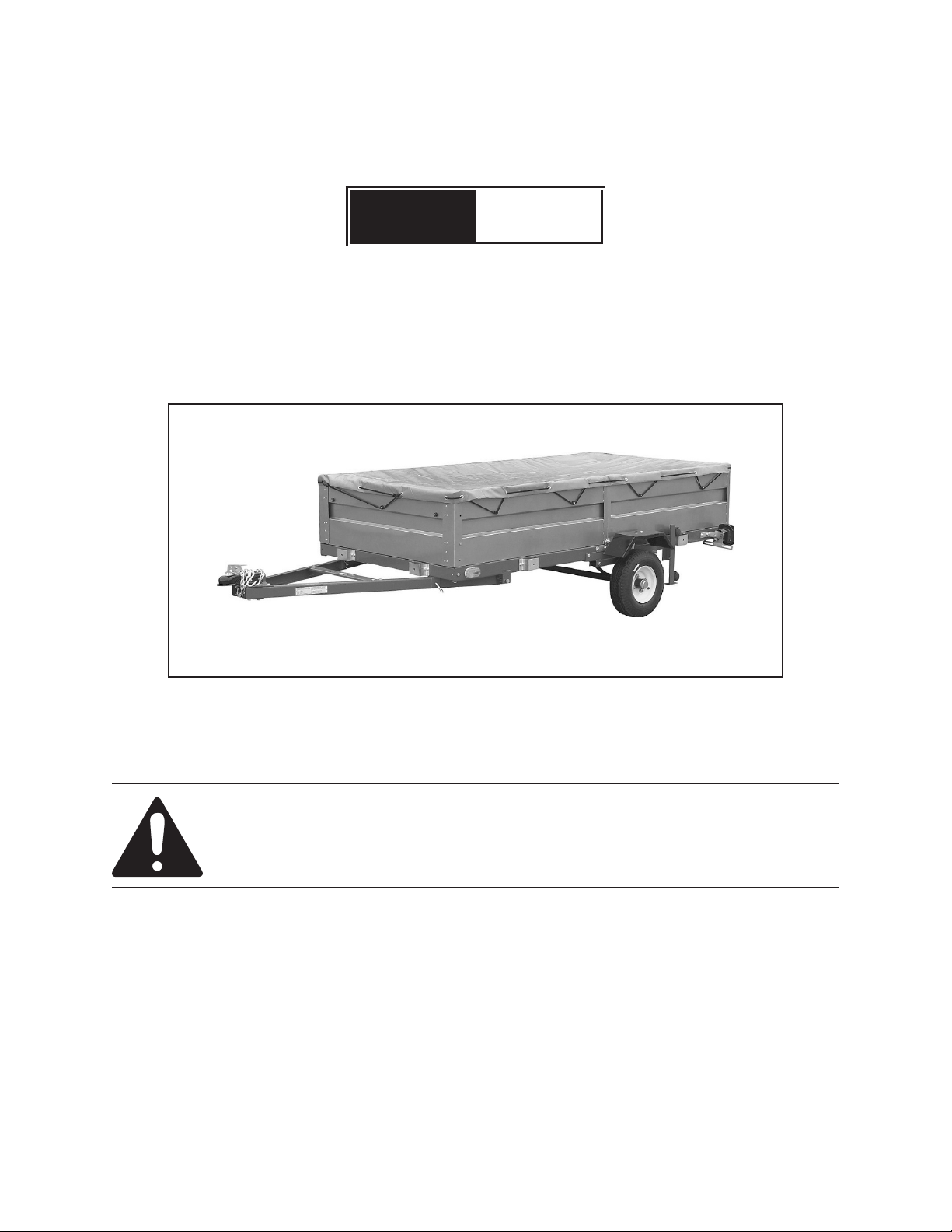
STEEL SIDE PANEL KIT
Model
(FOR USE WITH MODEL 42709 FOLDABLE UTILITY TRAILER)
47423
SET UP AND OPERATING INSTRUCTIONS
(MODEL 42709 TRAILER and TARP NOT INCLUDED. TARP SOLD SEPARATELY.
SHOWN FOR ILLUSTRATION PURPOSES ONLY)
Visit our website at: http://www.harborfreight.com
Read this material before using this product.
Failure to do so can result in serious injury.
SAVE THIS MANUAL.
Copyright© 2002 by Harbor Freight Tools®. All rights reserved. No portion of this manual or any artwork
contained herein may be reproduced in any shape or form without the express written consent of
Harbor Freight Tools. Diagrams within this manual may not be drawn proportionally. Due to continuing
improvements, actual product may differ slightly from the product described herein. Tools required for
assembly and service may not be included.
For technical questions or replacement parts, please call 1-800-444-3353.
Manual Revised 10a
Page 2

SPECIFICATIONS TABLE
Overall Dim. 96” L x 48-9/16” W x 15-7/8” H
Front Panel Dim. 48-9/16” W x 15-7/8” H x 2” T
Rear Panel Dim. 44-5/8” L x 15-7/8” H x 2” T
Side Panel Dim. 96” L x 15-7/8” H x 2” T
Rear Panel Latch Swing Over, Cam Slotted
Weight 92 Pounds
SAVE THIS MANUAL
You will need this manual for the
safety warnings and precautions, assembly,
operating, inspection, maintenance and
cleaning procedures, parts list and assembly
diagram. Keep your invoice with this manual.
Write the invoice number on the inside of the
front cover. Keep this manual and invoice in a
safe and dry place for future reference.
when using this product. ANSI-approved
safety impact goggles and heavy-duty
work gloves are available from Harbor
Freight Tools.
DRESS SAFELY. 6. Do not wear loose
clothing or jewelry, as they can become
caught in moving parts. Wear a
protective hair covering to prevent long
hair from becoming caught in moving
parts. If wearing a long-sleeve shirt, roll
sleeves up above elbows.
DO NOT OVERREACH.7. Keep proper
footing and balance at all times to
prevent tripping, falling, back injury,
etcetera.
INDUSTRIAL APPLICATIONS MUST 8.
FOLLOW OSHA REQUIREMENTS.
GENERAL SAFETY WARNINGS
AND PRECAUTIONS
KEEP WORK AREA CLEAN AND DRY. 1.
Cluttered, damp, or wet work areas invite
injuries.
KEEP CHILDREN AWAY FROM WORK 2.
AREA. Do not allow children to handle
this product.
STORE IDLE EQUIPMENT. 3. When not
in use, tools and equipment should be
stored in a dry location to inhibit rust.
Always lock up tools and equipment, and
keep out of reach of children.
DO NOT USE THIS PRODUCT 4.
IF UNDER THE INFLUENCE OF
ALCOHOL OR DRUGS. Read warning
labels on prescriptions to determine if
your judgement or reexes are impaired
while taking drugs. If there is any doubt,
do not attempt to use this product.
STAY ALERT.9. Watch what you are
doing at all times. Use common sense.
Do not use this product when you are
tired or distracted from the job at hand.
CHECK FOR DAMAGED PARTS.10.
Before using this product, carefully
check that it will operate properly and
perform its intended function. Check for
damaged parts and any other conditions
that may affect the operation of this
product. Replace or repair damaged or
worn parts immediately.
REPLACEMENT PARTS AND 11.
ACCESSORIES: When servicing, use
only identical replacement parts. Only
use accessories intended for use with
this product. Approved accessories are
available from Harbor Freight Tools.
MAINTAIN THIS PRODUCT WITH 12.
CARE. Keep this product clean and dry
for better and safer performance.
USE EYE AND HAND PROTECTION. 5.
Wear ANSI-approved safety impact
MAINTENANCE:13. For your safety,
service and maintenance should be
goggles and heavy-duty work gloves
REV 03f
Page 2 For technical questions, please call 1-800-444-3353. SKU 47423
Page 3

performed regularly by a qualied
technician.
USE THE RIGHT TOOL FOR THE 14.
JOB. Do not attempt to force small
equipment to do the work of larger
industrial equipment. There are certain
applications for which this equipment
was designed. It will do the job better
and more safely at the capacity for
which it was intended. Do not modify
this equipment, and do not use this
equipment for a purpose for which it was
not intended.
WARNING:15. The warnings, precautions,
and instructions discussed in this manual
cannot cover all possible conditions and
situations that may occur. The operator
must understand that common sense
and caution are factors, which cannot
be built into this product, but must be
supplied by the operator.
SPECIFIC PRODUCT
WARNINGS AND
PRECAUTIONS
THE MODEL 42709 TRAILER. Make
sure to attach the Steel Side Panel Kit to
the Trailer manufacturer’s recommended
assembly points.
ALWAYS EXAMINE THE STEEL SIDE 4.
PANEL KIT FOR LOOSE MOUNTING
BOLTS, STRUCTURAL CRACKS,
BENDS, DAMAGE, AND ANY OTHER
CONDITION THAT MAY AFFECT
ITS SAFE OPERATION. Do not use
the Steel Side Panel Kit even if minor
damage appears.
When installing the Steel Side Panel kit, 5.
the trailer must be located on a level,
solid surface, with tires blocked so that
the trailer cannot roll.
UNPACKING
When unpacking, check to make sure
all the parts shown on the Parts List (page
9) are included. If any parts are missing or
broken, please call Harbor Freight Tools at the
number shown on the cover of this manual as
soon as possible.
THIS STEEL SIDE PANEL KIT IS 1.
DESIGNED FOR USE ONLY WITH THE
MODEL 42709 TRAILER (AVAILABLE
FROM HARBOR FREIGHT TOOLS).
PROFESSIONAL TECHNICAL 2.
ASSEMBLY KNOWLEDGE IS
REQUIRED TO SECURELY AND
PERMANENTLY ATTACH THE STEEL
SIDE PANEL KIT TO THE MODEL
42709 TRAILER. ONLY A QUALIFIED
TECHNICIAN SHOULD PERFORM THE
ASSEMBLY.
MAKE SURE TO READ AND 3.
UNDERSTAND ALL INSTRUCTIONS
AND SAFETY PRECAUTIONS
AS OUTLINED IN THE
MANUFACTURER’S MANUAL FOR
Page 3For technical questions, please call 1-800-444-3353.SKU 47423
Page 4

PRODUCT OVERVIEW
The Steel Side Panel Kit is designed
for use only with the Model 42709 Trailer
(available from Harbor Freight Tools). Its
assembly onto the Trailer requires a 3/4”
thick, 4’ x 8’ plywood board (not provided).
Attaching the Steel Side Panel Kit to the
Trailer will also require drilling mounting
holes through the plywood board. ONLY A
QUALIFIED
TECHNICIAN SHOULD PERFORM THE ASSEMBLY.
ASSEMBLY INSTRUCTIONS
NOTE: For additional references to the parts
listed below, refer to the Assembly
Diagram (page 9).
DRILL 3/8” HOLES
notch
notch
FIGURE A
2. Use the measurements taken in Step #1
to mark and drill ten holes through the
3/4” thick, 4’ x 8’ plywood board. (See
Figure A.)
NOTE: You will need to notch out the
plywood to allow for the hinge as
shown in Figure A.
1. Measure the on-center distance between
the ten mounting holes located on the
front frame and two side frames of the
Trailer, locations indicated above.
ALIGN PRE-DRILLED
HOLES IN PLYWOOD
WITH FRAME
MOUNTING HOLES
3/4”, 4’x 8’
PLYWOOD
BOARD
MODEL
42709
TRAILER
FIGURE B
3. With assistance, place the 3/4” thick, 4’
x 8’ plywood board on the frame of the
Trailer. Make sure to align the ten predrilled holes in the plywood board with
the ten mounting holes on the front and
two sides of the Trailer frame.
(See Figure B.)
Place the Front Panel (1) on the front 4.
of the front end of the Trailer and
underneath the plywood board. Make
sure to align the two mounting holes at
the bottom of the Front Panel with the
Page 4 For technical questions, please call 1-800-444-3353. SKU 47423
Page 5

previously aligned holes in the plywood board and Trailer frame. Insert two Bolts (6)
downward through the holes in the Front Panel, plywood board, and Trailer frame. Then,
screw on a Nut (7) to each of the two Bolts extending through the underside of the Trailer
frame. Do not fully tighten the Nuts in this Step. (See Figure C.)
Place one Side Panel (2) on one side of the Trailer and underneath the plywood board. 5.
Slide the Side Panel forward into the “lip” of the Front Panel (1), and make sure to align
the four mounting holes at the bottom of the Side Panel with the previously aligned holes
in the plywood board and Trailer frame. Insert four Bolts (6) downward through the holes
in the Side Panel, plywood board, and Trailer frame. Then, screw a Nut (7) onto each of
the four Bolts extending through the underside of the Trailer frame. Do not fully tighten
the Nuts in this Step. (See Figure C.)
Repeat Step #5 for the remaining Side Panel (2). 6. (See Figure C.)
Align the 7. four mounting holes on one side of the Front Panel (1) with the four mounting
holes on the front end of one Side Panel (2). Insert four Bolts (8) through the four
mounting holes on the side of the Front Panel and through the four mounting holes on the
front end of the Side Panel. Then, screw a Nut (9) onto each of the four Bolts extending
through the inner side of the Side Panel. Do not fully tighten the Nuts in this Step. (See
Figure C.)
Repeat Step #7 for the other side of the Front Panel (1) and remaining Side Panel (2). 8.
(See Figure C.)
Check to make sure the Steel Side Panel Kit is setting square on the Trailer. 9. Then,
rmly wrench tighten all Bolts and Nuts. (See Figure C.)
REV 05k
Page 5For technical questions, please call 1-800-444-3353.SKU 47423
Page 6

TOP VIEW
SIDE
SIDE PANEL (2)
PANEL
FRONT
PANEL
BOLT
(8)
NUT
(9)
FRONT PANEL (1)
NUT (7)
BOLT (6)
SIDE
PANEL
PLYWOOD
TRAILER
SIDE VIEW
FRAME
SIDE PANEL (2)
FIGURE C
Page 6 For technical questions, please call 1-800-444-3353. SKU 47423
Page 7

To Attach And Remove The Rear Panel:
REAR PANEL (3)
LATCH (4)
(UNLOCKED
POSITION)
SIDE
PANEL (2)
EXTENDING ROD EXTENDING ROD
ROD CLAMP ROD CLAMP
TRAILER FRAME (REAR)
LATCH (4)
(LOCKED
POSITION)
SIDE
PANEL 2)
FIGURE D
1. The Rear Panel (3) is removable for loading and unloading. (See Figure D.)
To attach the Rear Panel (3) to the Steel Side Panel Kit, hold the Rear Panel with both 2.
hands and insert the Extending Rods at the bottom of the Rear Panel into the Rod
Clamps. Then, turn the Latch (4) on each rear end of the Side Panels (2) to their locked
position. (See Figure D.)
To temporarily remove the Rear Panel (3), turn the Latch (4) on each rear end of the Side 3.
Panels (2) to their unlocked position and pull the Extending Rods of the Rear Panel up
and out of the Rod Clamps. (See Figure D.)
INSPECTION, MAINTENANCE, AND CLEANING
BEFORE EACH USE,1. inspect the general condition of the Steel Side Panel Kit. Check
for loose mounting bolts, misalignment or binding of moving parts, cracked, bent, or
broken parts and any other condition that may affect its safe operation. Importantly,
check the Steel Side Panel Kit regularly to assure the welds remain solid. If abnormal
noise or vibration occurs, have the problem corrected before further use. Do not use
damaged equipment.
TO CLEAN,2. use only water and a mild detergent.
REV 03f
Page 7For technical questions, please call 1-800-444-3353.SKU 47423
Page 8

PLEASE READ THE FOLLOWING CAREFULLY
THE MANUFACTURER AND/OR DISTRIBUTOR HAS PROVIDED THE PARTS LIST AND ASSEMBLY
DIAGRAM IN THIS MANUAL AS A REFERENCE TOOL ONLY. NEITHER THE MANUFACTURER OR
DISTRIBUTOR MAKES ANY REPRESENTATION OR WARRANTY OF ANY KIND TO THE BUYER THAT HE
OR SHE IS QUALIFIED TO MAKE ANY REPAIRS TO THE PRODUCT, OR THAT HE OR SHE IS QUALIFIED
TO REPLACE ANY PARTS OF THE PRODUCT. IN FACT, THE MANUFACTURER AND/OR DISTRIBUTOR
EXPRESSLY STATES THAT ALL REPAIRS AND PARTS REPLACEMENTS SHOULD BE UNDERTAKEN BY
CERTIFIED AND LICENSED TECHNICIANS, AND NOT BY THE BUYER. THE BUYER ASSUMES ALL RISK
AND LIABILITY ARISING OUT OF HIS OR HER REPAIRS TO THE ORIGINAL PRODUCT OR REPLACEMENT
PARTS THERETO, OR ARISING OUT OF HIS OR HER INSTALLATION OF REPLACEMENT PARTS THERETO.
PARTS LIST / ASSEMBLY DIAGRAM
Part Description
1 Front Panel 1
2 Side Panel 2
3 Rear Panel 1
4 Latch 2
5 Plastic Roller 14
6 Bolt (M10 x 16) 10
Qty.
Part Description
7 Nut (M10) 12
8 Bolt (M8 x 16) 8
9 Nut (M8) 12
11 Bolt (M8 x 25) 2
12 Washer 4
Qty.
NOTE: Some parts are listed and shown for illustration purposes only, and are not available
individually as replacement parts.
REV 03f
Page 8 For technical questions, please call 1-800-444-3353. SKU 47423
 Loading...