

Page 1
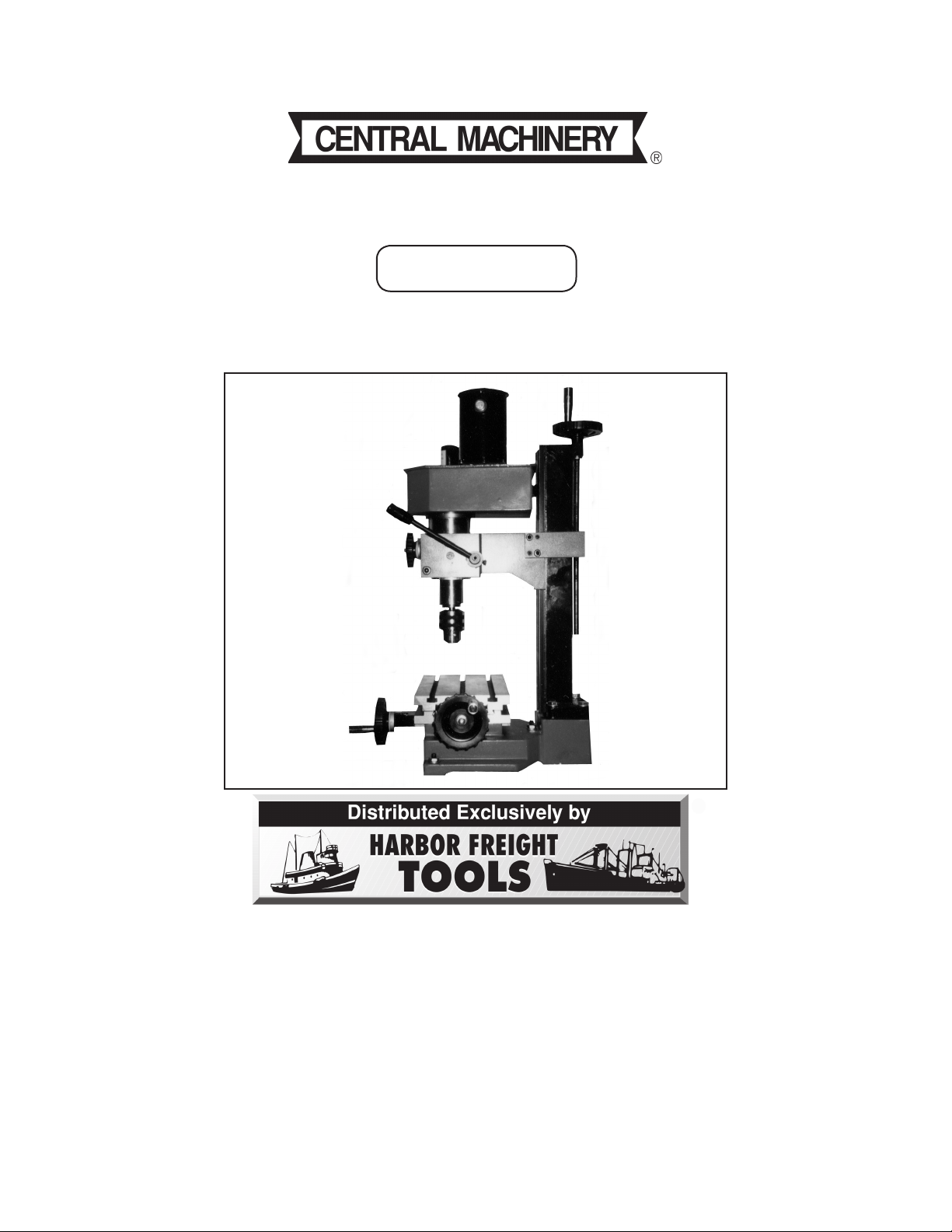
MICRO MILL/DRILL MACHINE
®
Model 47158
ASSEMBLY AND OPERATING INSTRUCTIONS
3491 Mission Oaks Blvd., Camarillo, CA 93011
Visit our Web site at: http://www.harborfreight.com
Copyright© by Harbor Freight Tools®. All rights reserved. No portion of this
manual or any artwork contained herein may be reproduced in any shape or form
without the express written consent of Harbor Freight Tools.
For technical questions, please call 1-800-444-3353.
Page 2

SPECIFICATIONS TABLE
Electrical Requirements 120 V / 6 0 Hz / 1/5 HP
2 Speed Ranges High: 100-2,000 RPM / Low: 100-1,000 RPM
Maximum Chuck Capacity 25/64” Drill Bit / 25/64” End Mill / 3/4” Face Mill
Maximum X Travel 9”
Maximum Y Travel 4”
Maximum Z Travel 8-1/2”
X, Y, Z Graduations .001” / Line
Table Size 9-3/8” x 5-3/8”
Table Slot 5/16” x 5/8”
Throat Depth 5-1/2”
Swing Diameter 11”
Base Size 10-1/8” x 9-3/8”
Spindle Stroke 1-3/16”
Spindle Taper MT2
Weight 103 Pounds
SAVE THIS MANUAL
You will need this manual for the safety warnings and precautions, assembly, operating, inspection, maintenance and cleaning procedures, parts list and
assembly diagram. Keep your invoice with this manual. Write the invoice
number on the inside of the front cover. Keep this manual and invoice in a safe
and dry place for future reference.
GENERAL SAFETY WARNINGS AND PRECAUTIONS
1. KEEP WORK AREA CLEAN AND DRY. Cluttered, damp, or wet work areas
invite injuries.
2. KEEP CHILDREN AWAY FROM WORK AREA. Do not allow children to handle
this product.
3. STORE IDLE EQUIPMENT. When not in use, tools and equipment should be
stored in a dry location to inhibit rust. Always lock up tools and equipment, and
keep out of reach of children.
4. DO NOT USE THIS PRODUCT IF UNDER THE INFLUENCE OF ALCOHOL OR
DRUGS. Read warning labels on prescriptions to determine if your judgement or
reflexes are impaired while taking drugs. If there is any doubt, do not attempt to
use this product.
For technical questions, please call 1-800-444-3353.
Page 2SKU 47158
Page 3

5. USE EYE AND BREATHING PROTECTION. Wear ANSI approved safety impact
eyeglasses when using this product. Also, use an ANSI approved dust mask if
the operation produces excessive dust. ANSI approved safety impact
eyeglasses and dust masks are available from Harbor Freight Tools.
6. DRESS SAFELY. Do not wear loose clothing or jewelry, as they can become
caught in moving parts. Wear a protective hair covering to prevent long hair from
becoming caught in moving parts. If wearing a long-sleeve shirt, roll sleeves up
above elbows.
7. DO NOT OVERREACH. Keep proper footing and balance at all times to prevent
tripping, falling, back injury, etcetera.
8. INDUSTRIAL APPLICATIONS MUST FOLLOW OSHA REQUIREMENT.
9. STAY ALERT. Watch what you are doing at all times. Use common sense. Do
not use this product when you are tired or distracted from the job at hand.
10. CHECK FOR DAMAGED PARTS. Before using this product, carefully check that
it will operate properly and perform its intended function. Check for damaged
parts and any other conditions that may affect the operation of this product. Replace or repair damaged or worn parts immediately.
11. REPLACEMENT PARTS AND ACCESSORIES: When servicing, use only
identical replacement parts. Only use accessories intended for use with this
product. Approved accessories are available from Harbor Freight Tools.
12. MAINTAIN THIS PRODUCT WITH CARE. Keep this product clean, dry, and keep
all cutting bits sharp for better and safer performance.
13. MAINTENANCE: For your safety, service and maintenance should be performed
regularly by a qualified technician.
14. USE THE RIGHT TOOL FOR THE JOB. Do not attempt to force a small tool or
attachment to do the work of a larger industrial tool. There are certain
applications for which this tool was designed. It will do the job better and more
safely at the rate for which it was intended. Do not modify this tool, and do not
use this tool for a purpose for which it was not intended.
15. WARNING: The warnings, precautions, and instructions discussed in this manual
cannot cover all possible conditions and situations that may occur. The operator
must understand that common sense and caution are factors, which cannot be
built into this product, but must be supplied by the operator.
For technical questions, please call 1-800-444-3353.
Page 3SKU 47158
Page 4

SPECIFIC PRODUCT WARNINGS AND PRECAUTIONS
1. MAINTAIN A SAFE WORKING ENVIRONMENT. Keep the work area well lit.
Make sure there is adequate surrounding workspace. Always keep the work area
free of obstructions, grease, oil, trash, and other debris. Do not use the Micro
Mill/Drill Machine in areas near flammable chemicals, dusts, and vapors. Do not
use the Micro Mill/Drill Machine in a damp or wet location.
2. GROUND THIS PRODUCT. The electrical Power Cord/Plug (part #128) for this
product is equipped with a grounded, 3-prong Plug. Never remove the grounding
prong or modify the Plug in any way. Do not use adapter plugs with this product.
To comply with the National Electric Code, and to provide additional protection
from the risk of electrical shock, this product should only be connected to a 120
Volt, 3-hole electrical outlet that is protected by a Ground Fault Circuit Interrupter
(GFCI). (See Assy. Diagram.)
3. IF AN EXTENSION CORD (not provided) IS USED, MAKE SURE TO USE
ONLY UL APPROVED CORDS HAVING THE CORRECT GAUGE AND
LENGTH. (See Figure A.)
AWG RATING CHART - 120 VOLT
FIGURE A
4. KEEP ALL SAFETY GUARDS IN PLACE, IN PROPER ADJUSTMENT, AND IN
PROPER ALIGNMENT.
5. REDUCE THE RISK OF ACCIDENTAL STARTING. Make sure the Forward/Re-
verse Switch (part #125) is in the “OFF” position before plugging the Power Cord/
Plug (part #128) into a grounded, 3-hole, 120 Volt, electrical outlet.
(See Figure B, and Assy. Diagram.)
6. PRIOR TO STARTING THE MICRO MILL/DRILL MACHINE, MAKE SURE ALL
ADJUSTING KEYS AND WRENCHES ARE REMOVED FROM THE TOOL.
7. DO NOT USE ROTARY PLANERS, WIRE WHEELS, OR ROUTER BITS ON
THIS MICRO MILL/DRILL MACHINE.
For technical questions, please call 1-800-444-3353.
Page 4SKU 47158
Page 5

8. BEFORE DRILLING OR CUTTING, TURN ON THE MICRO MILL/DRILL
MACHINE AND CHECK FOR BIT WOBBLE OR MACHINE VIBRATION. If this is
found, turn off the tool and correct the problem before using.
9. SECURE THE WORKPIECE. Whenever possible, secure the workpiece to the
Worktable (part #105) with a vise or clamps. If the workpiece begins to spin, do
not attempt to stop it with your hands. Turn the Micro Mill/Drill Machine OFF, and
wait until the workpiece stops spinning before attempting to remove it.
(See Figure B, and Assy. Diagram.)
10. ALWAYS FEED THE WORKPIECE INTO AND AGAINST THE ROTATIONAL
DIRECTION OF A BIT OR CUTTER.
11. WHEN DRILLING OR CUTTING SOFTER MATERIALS OR SMALL HOLES,
USE THE HIGHER SPEEDS. WHEN DRILLING OR CUTTING HARDER
MATERIALS OR LARGER HOLES, USE THE SLOWER SPEEDS.
12. NEVER LEAVE THE MICRO MILL/DRILL MACHINE UNATTENDED WHEN IT
IS RUNNING. Turn off the tool, and wait until it has completely stopped before
leaving.
13. ALWAYS UNPLUG THE MICRO MILL/DRILL MACHINE FROM ITS
ELECTRICAL SUPPLY SOURCE BEFORE PERFORMING ANY INSPECTION,
MAINTENANCE, OR CLEANING PROCEDURES.
14. WARNING: Some dust created by power sanding, sawing, grinding, drilling, and
other construction activities, contain chemicals known (to the State of California)
to cause cancer, birth defects or other reproductive harm. Some examples of
these chemicals are: lead from lead-based paints, crystalline silica from bricks
and cement or other masonry products, arsenic and chromium from chemically
treated lumber. Your risk from these exposures varies, depending on how often
you do this type of work. To reduce your exposure to these chemicals: work in
a well ventilated area, and work with approved safety equipment, such as those
dust masks that are specially designed to filter out microscopic particles.
(California Health & Safety Code 25249.5, et seq.)
15. WARNING: People with pacemakers should consult their physician(s) before
using this product. Operation of electrical equipment in close proximity to a heart
pacemaker could cause interference or failure of the pacemaker.
For technical questions, please call 1-800-444-3353.
Page 5SKU 47158
Page 6

UNPACKING
When unpacking, check to make sure all the parts shown on the Parts Lists on pages 12
and 13 are included. If any parts are missing or broken, please call Harbor Freight Tools
at the number shown on the cover of this manual as soon as possible.
CLEANING, ASSEMBLY, AND MOUNTING INSTRUCTIONS
NOTE: For additional references to the parts listed below, refer to the Assembly
Diagram on page 14.
To Clean The Micro Mill/Drill Machine:
1. When manufactured, the Micro Mill/Drill Machine has a special rust-proof coating applied to its outer parts and should be removed prior to use. To remove the
coating, use a clean cloth and a mild solvent. Then, lubricate all moving parts
with a premium quality, lightweight machine oil.
To Assemble The Micro Mill/Drill Machine:
1. The Lifting Hand Wheel, Longitudinal Feed Hand Wheel, Cross Feed Hand
Wheel, and Fine Feeding Hand Wheel (parts #97) must be assembled prior to
using the Micro Mill/Drill Machine. The four Wheels are each identical in size and
shape, and must be properly attached to the Worm Shaft (part #61), the Lifting
Screw (part #95), and the two Lengthways Screws (part #111).
(See Figure B, and Assy. Diagram.)
2. To attach the four Wheels (parts #97) to the Micro Mill/Drill Machine, insert one
wheel each onto the end of the Worm Shaft (part #61), the Lifting Screw (part
#95), and the two Lengthways Screws (part #111). Then firmly secure each
Wheel, using one Washer (part #67), and one Top Nut (part #68).
(See Figure B, next page, and Assy. Diagram.)
To Mount The Micro Mill/Drill Machine On A Workbench:
1. CAUTION: Make sure the Micro Mill/Drill Machine is mounted on a flat, level,
sturdy, workbench surface capable of supporting the weight of the Micro Mill/Drill
Machine, additional tools, accessories, and the workpiece.
For technical questions, please call 1-800-444-3353.
Page 6SKU 47158
Page 7

2. NOTE: When mounting the Micro Mill/Drill Machine on a workbench, you will
need four 3/8” diameter bolts of appropriate length, four lock washers, and four
nuts (not provided).
LIFTING HAND WHEEL
(#97)
SPINDLE
BOX
(#24)
FORWARD
OFF
REVERSE
SWITCH
(#125)
VARIABLE
SPEED
KNOB (#122)
WORK
TABLE
(#105)
HIGH/LOW SPEED KNOB
CLUTCH
LEVER (#65)
HAND WHEEL (#97)
(#124)
CLUTCH LEVER
FINE FEEDING
FINE FEEDING
HAND WHEEL
HANDLE SHAFT
(#87)
CHUCK (#132)
LONGITUDINAL FEED
HAND WHEEL
(#97)
LIFTING HAND WHEEL
(#97)
HANDLE
SHAFT
(#87)
(#65)
SPINDLE
BOX
(#24)
(#97)
CHUCK
(#132)
WORK
TABLE
(#105)
CROSS FEED
HAND WHEEL (#97)
LONGITUDINAL FEED
HAND WHEEL (#97)
FIGURE B
3. With assistance, position the Micro Mill/Drill Machine in the desired location on
the top of the workbench. Use the four mounting holes in the Base (part #74) of
the Micro Mill/Drill Machine as a template, and trace with a pencil on the top of
the workbench four 3/8” diameter mounting holes . Then, temporarily remove the
Micro Mill/Drill Machine from the workbench. (See Assy. Diagram.)
4. Where the four pencil marks are located, drill four 3/8” diameter holes completely
through the top of the workbench.
For technical questions, please call 1-800-444-3353.
Page 7SKU 47158
Page 8

5. Then, secure the Micro Mill/Drill Machine to the workbench, using the four 3/8”
diameter bolts of appropriate length, four lock washers, and four nuts as
mentioned in Step #2.
MACHINE ADJUSTMENT INSTRUCTIONS
NOTE: For additional references to the parts listed below, refer to the Assembly
Diagram on page 14.
To Use The Adjustment Controls:
1. CAUTION: ALWAYS TURN OFF THE MICRO MILL/DRILL MACHINE, UNPLUG
ITS ELECTRICAL POWER CORD/PLUG (part #128), AND WAIT UNTIL IT
COMPLETELY STOPS RUNNING BEFORE MAKING ANY ADJUSTMENTS.
2. To adjust the height of the Spindle Box (part #24) to accommodate the work-
piece being milled/drilled; turn the Lifting Hand Wheel (part #97) clockwise to
raise the Spindle Box, and turn the Lifting Hand Wheel counterclockwise to lower
the Spindle Box. (See Figure B, and Assy. Diagram.)
3. To lower and raise the Chuck (part #132); pull the Handle Shaft (part #87)
down to lower the Chuck. Pull the Handle Shaft up to raise the Chuck.
(See Figure B, and Assy. Diagram.)
4. To adjust the fine feeding mechanism; push in on the Clutch Lever (part #65)
which is located on the Fine Feeding Hand Wheel (part #97). Turn the Fine
Feeding Hand Wheel clockwise to bring the tip of the Chuck (part #132) up. Turn
the Fine Feeding Hand Wheel counterclockwise to bring the tip of the Chuck
down. The Fine Feeding Hand Wheel may be adjusted from 0” to 1-1/4” up or
down. NOTE: For normal, manual feeding, make sure the Clutch Lever is pulled
out. (See Figure B, and Assy. Diagram.)
5. To move the Worktable (part #105)to the front and to the back; turn the
Longitudinal Feed Hand Wheel (part #97) clockwise to position the Worktable
toward the front of the machine. Turn the Longitudinal Feed Hand Wheel
counterclockwise to position the Worktable toward the back of the machine. (See
Figure B, and Assy. Diagram.)
6. To move the Worktable (part #105) to the right and to the left; turn the Cross
Feed Hand Wheel (part #97) clockwise to position the Worktable to the right.
Turn the Cross Feed Hand Wheel counterclockwise to position the Worktable to
the left. (See Figure B, and Assy. Diagram.)
For technical questions, please call 1-800-444-3353.
Page 8SKU 47158
Page 9

7. To turn the machine on/off, and adjust the rotational direction of the Chuck
(part #132); turn the Switch (part #125) from its “OFF” position to its “FORWARD”
position to turn on the machine and for a clockwise rotation of the Chuck. Turn
the Switch from its “OFF” position to its “REVERSE” position to turn on the ma-
chine and for a counterclockwise rotation of the Chuck. To turn off the
machine, turn the Switch to its “OFF” position.
(See Figure B, and Assy. Diagram.)
8. To adjust the speed at which the Chuck (part #132) rotates; First set the
High/Low Knob (part #124) until the letter “L” appears on its dial so that the Mirco
Mill/Drill Machine begins running at its low speed range (100-1,000 RPM). Turn
the Machine on. Note: Adjusting the High/Low Know (part #124) until the letter
“H” appears on its dial, will run the machine at its high speed range (100-2,000
RPM). Once the HIGH or LOW speed range has been set, use the Variable
Speed Knob (part #122) to fine-adjust the RPM at which the Chuck rotates.
NOTE: It is recommended to use a higher speed for softer materials or small
holes. Use a lower speed for harder materials and larger holes. (See Figure B,
and Assy. Diagram.)
OPERATING INSTRUCTIONS
NOTE: For additional references to the parts listed below, refer to the Assembly
Diagram on page 14.
1. CAUTION: Make sure the Switch (part #125) on the Micro Mill/Drill Machine is in
its “OFF” position. Then, plug the Power Cord/Plug (part #128) into the nearest
120 volt, grounded, 3-prong electrical outlet. (See Figure B, and Assy. Dia-
gram.)
2. Check to make sure the Handle Shaft (part #87) is in its full “UP” position.
(See Figure B, and Assy. Diagram.)
3. Place the workpiece on the Worktable (part #105) and, if possible, firmly secure the
workpiece to the Worktable with clamps (not provided).
(See Figure B, and Assy. Diagram.)
4. Insert the shank of the drill bit/cutting tool (not provided) all the way up into the
Chuck (part #132). Then, use the Chuck Key to tighten the Chuck onto the drill
bit/cutting tool. NOTE: There are three tightening/loosening holes in the Chuck.
Make sure to use the Chuck Key in all three holes.
(See Figures B, and C.)
For technical questions, please call 1-800-444-3353.
REV 08/03
Page 9SKU 47158
Page 10

(CLOCKWISE TO TIGHTEN. COUNTERCLOCKWISE TO LOOSEN.)
CHUCK (#132)
CHUCK KEY
FIGURE C
5. If necessary, use the Lifting Hand Wheel, Longitudinal Feed Hand Wheel, Cross
Feed Hand Wheel, and Fine Feeding Hand Wheel (parts #97) to adjust the Micro
Mill/Drill Machine for the work to be done. NOTE: Do not attempt to make any
further adjustments while the machine is running.
(See Figure B, and Assy. Diagram.)
6. Set the High/Low Speed Knob (part #124) to the speed range required.
NOTE: Do not attempt to make any further adjustments while the machine is run-
ning. (See Figure B, and Assy. Diagram.)
7. Set the Variable Speed Knob (part #122) to fine-adjust the speed range.
NOTE: Do not attempt to make any further adjustments while the machine is run-
ning. (See Figure B, and Assy. Diagram.)
8. Turn the Switch (part #125) from its “OFF” position to either its “FORWARD” position or its “REVERSE” position, depending on the work to be done. NOTE: Do
not attempt to turn the Switch directly from its “FORWARD” position to its “REVERSE” position, or its “REVERSE” position to its “FORWARD” position, while
the machine is running. To change the rotational direction, turn the Switch to its
“OFF” position. Wait until the machine completely stops. Then, change the rotational direction. (See Figure B, and Assy. Diagram.)
9. After testing the machine in Forward and Reverse position, evaluate the machine’s operation; check for loose or damaged parts, wobbling of the chuck or
any other unusual situation. If the machine appears to be operating normally, the
Micro Mill/Drill Machine is ready to use.
10. Once the work is completed, make sure to turn the Switch (part #125) to its “OFF”
position. Wait until the machine has completely stopped. Unplug the Micro Mill/Drill
Machine from its electrical power source. Remove the workpiece. And re m o v e
the drill bit/cutting tool.
For technical questions, please call 1-800-444-3353.
Page 10SKU 47158
Page 11

INSPECTION, MAINTENANCE, AND CLEANING
NOTE: For additional references to the parts listed below, refer to the Assembly
Diagram on page 14.
1. CAUTION: Always unplug the Power Cord/Plug (part #128) from its 120 volt electrical outlet before performing any inspection, maintenance, or cleaning.
2. BEFORE EACH USE, inspect the general condition of the Micro Mill/Drill Machine. Check for loose screws, misalignment or binding of moving parts, cracked
or broken parts, damaged electrical wiring, and any other condition that may
affect its safe operation. If abnormal noise or vibration occurs, have the problem
corrected before further use. Do not use damaged equipment.
3. DAILY: With a soft brush, cloth, or vacuum, remove all debris from the Micro Mill/
Drill Machine. Then, use a premium quality, lightweight machine oil to lubricate all
moving parts.
PLEASE READ THE FOLLOWING CAREFULLY
THE MANUFACTURER AND/OR DISTRIBUTOR HAS PROVIDED THE PARTS LIST AND
ASSEMBLY DIAGRAM IN THIS MANUAL AS A REFERENCE TOOL ONLY. NEITHER THE
MANUFACTURER OR DISTRIBUTOR MAKES ANY REPRESENTATION OR WARRANTY
OF ANY KIND TO THE BUYER THAT HE OR SHE IS QUALIFIED TO MAKE ANY REPAIRS
TO THE PRODUCT, OR THAT HE OR SHE IS QUALIFIED TO REPLACE ANY PARTS OF
THE PRODUCT. IN FACT, THE MANUFACTURER AND/OR DISTRIBUTOR EXPRESSLY
STATES THAT ALL REPAIRS AND PARTS REPLACEMENTS SHOULD BE UNDERTAKEN
BY CERTIFIED AND LICENSED TECHNICIANS, AND NOT BY THE BUYER. THE BUYER
ASSUMES ALL RISK AND LIABILITY ARISING OUT OF HIS OR HER REPAIRS TO THE
ORIGINAL PRODUCT OR REPLACEMENT PARTS THERETO, OR ARISING OUT OF
HIS OR HER INSTALLATION OF REPLACEMENT PARTS THERETO.
For technical questions, please call 1-800-444-3353.
Page 11SKU 47158
Page 12

PARTS LIST
Clutch
For technical questions, please call 1-800-444-3353.
Page 12SKU 47158
Page 13

PARTS LIST
Variable Speed
High/Low Speed
Power Cord/
Lengthways
For technical questions, please call 1-800-444-3353.
Page 13SKU 47158
Page 14

ASSEMBLY DIAGRAM
NOTE: Some parts are listed and shown for illustration purposes only, and are not avail-
able individually as replacement parts.
For technical questions, please call 1-800-444-3353.
Page 14SKU 47158
Page 15

Green Lamp
SCHEMATIC DIAGRAM
Yellow Lamp
(fault)
Fuse
110V/60Hz
Forward/Off/Reverse
Switch
Potentiometer
Motor
For technical questions, please call 1-800-444-3353.
REV 08/04
Page 15SKU 47158
Page 16

WIRING DIAGRAM
1 2 3 4
A
B
C
D
4321
D
C
B
A
A
B
C
BR
KBL406
D1
FR207
B
D7
IN4007
D6
IN4007
D8
IN4007
D9
IN4007
C1
47uF/25V
C5
47uF/25V
JK2A
JK1A
JK3A
Vin
GND
+12V
7812
C12
100uF/50V
C11
100uF/50V
-12V
+12V
R2
10K
R3
220K
U4
TIL113
D3
IN4007
R8
68K
D4
DW18V
C4
47uF/25V
R42
470
D2
IN4007
C2
473/250V
R5
100K
R4
100
-
+
U5B
LM324
-
+
U5A
LM324
JK3B
DEG-12VDC
C6
220uF/25V
D10
IN4007
D11
IN4007
R49
220K
R50
24K
R45
12KVR1
3296-503
VR2
3296-503
C15
105
R46
33K
R47
47K
R1
0.33
+12V
-12V
-12V
+12V
VR
10D681
R2-2
12K
R9
1.8K
JK2B
+12V
Vin
GND
-12V
7912
P1 P4
AC3 AC4
5
6
7
Q1
MTW-20N50E
470
FT2813-220-15DP
L
DEG-12VDC
DEG-12VDC
DC2
U3
TIL113
DC1
JK1B
D5
IN4007
KG
For technical questions, please call 1-800-444-3353.
REV 07/06
Page 16SKU 47158
 Loading...