

Page 1

®
QUICK ACTION
8-POSITION W ORKBENCH
47078
ASSEMBLY & OPERATING INSTRUCTIONS
3
Page 2

THANK YOU for choosing a HARBOR FREIGHT TOOLS product. For future reference, please
complete the owner’s record below:
Model
___________ Serial No._____________ Purchase Date_____________
Save This Manual
You will need the manual for the safety warnings and precautions, assembly instructions, operating
and maintenance procedures, parts list and diagram. Keep your invoice with this manual. Write the
invoice number on the inside of the front cover. Keep the manual and invoice in a safe and dry
place for future reference.
Technical Specifications
Construction: Cast Aluminum Frame and Steel with welded hinges
Height: 30-3/8"
Table Size: 16" W x 24" Long with 4" clamp travel
Max. Load Capacity: 375 LBS.
The Workbench has 12 dog Holes and 12 Dogs. It has eight (8) adjustment settings
along with a 23-5/8" Ruler.
Safety Warnings and Precautions
WARNING: When using product, basic safety precautions should always be followed to
reduce the risk of personal injury and damage to equipment.
Read all instructions before using this product!
1. Keep work area clean. Cluttered areas invite injuries.
2. Observe work area conditions. Do not use this product in damp or wet locations. Don’t
expose to rain. Keep work area well lighted.
3. Store idle equipment. When not in use, products must be stored in a dry location to inhibit
rust. Always lock up products and keep out of reach of children.
4.
Use the right product for the job. There are certain applications for which this product was
designed. It will do the job better and more safely at the rate for which it was intended. Do not
modify this product and do not use this product for a purpose for which it was not intended.
5. Check for damaged parts. Before using any product, any part that appears damaged should
be carefully checked to determine that it will operate properly and perform its intended function.
Check for any broken or damaged parts and any other conditions that may affect its operation.
Replace or repair damaged or worn parts immediately.
6. Replacement parts and accessories. When servicing, use only identical replacement parts.
Use of any other parts will void the warranty.
7. Do not operate product if under the influence of alcohol or drugs. Read warning labels on
prescriptions to determine if your judgment or reflexes are impaired while taking drugs. If there
is any doubt, do not operate the product.
#47078 Page 2
Page 3
8. Use eye and ear protection. Always wear ANSI approved impact safety goggles.
9. Do not exceed products maximum load capacity. Make certain that the Workbench can
support all tools and accessories, as well as any workpiece.
10. Avoid Sharp edges when assembling.
11. Always check hardware and assembled parts after assembling. Place in an area that is
flat and level. All connections should be tight and hardware tightened.
12. Do not allow children to play on, stand upon or climb upon the Workbench.
Warning: The warnings, cautions, and instructions discussed in this instruction manual cannot
cover all possible conditions and situations that may occur. It must be understood by
the operator that common sense and caution are factors which cannot be built into
this product, but must be supplied by the operator.
Assembly
Your Quick Action 8-Position Workbench will require complete assembly prior to use. It is important
that you read the entire manual to become familiar with the product BEFORE use. Before
assembling the Workbench be sure that you have all parts described in the Parts List and Assemby
Diagram located on the last pages of this manual.
Step 1) Locate the two (2) Left Leg Stand Frames (#26). Attach Tool Holder (front) (#24) to
the Left Leg Stand Frames (#26) by inserting a Hex Bolt (#29) through each corner
of the Tool Holder (front) and through the Left Leg Stand Frame(s). Slide on Flat
Washer (#19) and fasten Hex Nut M6 (#18).
Step 2) Locate the two (2) Right Leg Stand Frames (#27) and attach Tool Holder (back) (#25)
by inserting a Hex Bolt (#29) through each corner of the Tool Holder (back) (#25) and
through the Right Leg Stand Frame (#27). Slide on Flat Washers (#19) and fasten in
place with Hex Nut M6 (#18).
Step 3) Attach the Left Leg Stand Frames (#26) to Right Leg Stand Frames (#27). Inser t
Hex Bolt (#20) through Right Leg Stand Frames (#27) and slide on Spacer (#17)
then slide on Left Leg Stand Frame and Washer (#19). Secure with Hex Nut (#18).
Repeat for second side of Workbench-see Figure 1.
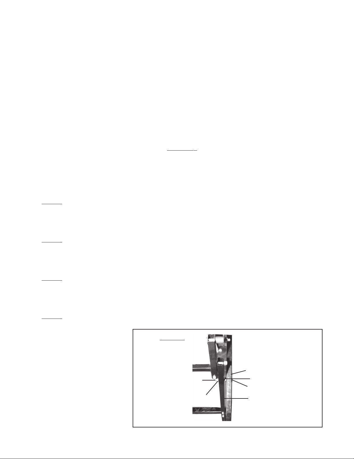
Step 4) Attach the Grip (#28) to the lowest hole in the top extension of the Left Leg Stand
Frames (#26) with Hex Bolt (#29) Washer (#19) and Hex Nut (#18)-see Figure 2.
Figure 1
Right Leg Stand Frame (#27)
Hex Nut (#18)
Washer (#19)
Spacer (#17)
Hex Bolt (#20)
Left Leg Stand Frame
(#26)
#47078 Page 3
Page 4

Washer (#15) with He x Nut (#14)
Hex Nut (#18)
Washer (#19)
Figure 2
U-Frame Channel (#10)
Cross Head Bolt (#16)
Grip (#28)
Hex Bolt (#29)
Washer (#19)
Hex Nut (#18)
Step 5) Through the center hole in the extension, insert Hex Bolt (#29), slide on Washer
(#19) and fasten with Nut (#18)-see Figure 2.
Step 6) Set the U-Frame Channel (#10) on top of the Right Leg Stand Frame (#27) as shown
in Figure 2. Attach the U-Frame Channel (#10) to the Right Leg Stand Frame (#27)
with Cross Head Bolt (#16); slide on Washer (#15) and tighten on Hex Nut (#14)-see
Figure 2.
Step 7) Attach the Left Leg Frame Stand (#26) extension to the U-Frame Channel (#10).
First, hold the Spacer 22 mm (#9) between the Left Leg Frame Stand (#26) and the
U-Frame Channel (#10), then insert the Cross Head Bolt (#8) through Left Leg
Frame Stand (#26) through Spacer (#9) and through U-Frame Channel (#10). Slide
on Washer (#15) and Nut (#14)-refer to Figure 3.
Figure 3
Spacer (#9)
Washer (#15) and Nut (#14)
Left Leg Frame Stand (#26)
U-Frame Channel (#10)
Cross Head Bolt (#8)
Step 8) On the underside of the U-Frame Channel (#10), insert the Sliding Locking
Block (#13) with Spring (#12) (see Figure 4) and Check Pawl (#11). On the top of
the U-Frame Channel, set the Connecting Part (#7).
Figure 4
Spring (#12)
Sliding Locking
Block (#13)
#47078 Page 4
Page 5

Step 9) Lay the Table Top Back (#6) on top of the Connecting Parts (#7). Through the inside
hole, insert Cross Head Bolt (#3) with Washer (#4) so that it threads down through
the Connecting Part (#7) and into the Check Pawl (#11) and Sliding Locking
Block (#13).
Step 10) Through the outside holes in the Table Top Back (#6), thread the Push Button (#2)
into the Connecting Part (#7) and into the Check Pawl (#11) and Sliding Locking
Block (#12).
Step 11) Lay the TableTop (front) (#23) onto the Threaded Sliding Blocks (#21) which are set
in place on the U-Frame Channel (#10). Screw in Cross Head Bolt (#22) with
Washer (#4) through the Table Top (front) and into the Threaded Sliding Blocks (#21).
Step 12) As necessary, attach Rubber Feet (#30) to each Leg Stand Frame.
Operation
The Quick Action 8-Position Workbench folds for easy travel and storage.
Step 1) The Table Top (front) (#23) can be moved by turning the Handles on the U-Frame
Channel (#10). Turning the Handle clockwise will move the Table Top in towards the
other Table Top. Turning the Handle counterclockwise will move the Table
Top (front) (#23) out.
Step 2) Pressing on the red Push Buttons (#2) with your thumb allows you to grasp the Table
Top (back) (#6) with your hands and fingers and slide it forward or backward while
the Push Buttons (#2) are pressed down. Releasing the Push Buttons (#2) will lock
the Table into place-see Figure 5.
Figure 5
Step 3) The Swivel Pegs (#1) and Peg Supports (#5) can be placed into any hole in the Work
Table top provide a block to secure and block your workpiece.
PLEASE READ THE FOLLO WING CAREFULLY
THE MANUFACTURER AND/OR DISTRIBUTOR HAS PRO VIDED THE PARTS DIAGRAM IN THIS MANUAL AS A REFERENCE
TOOL ONLY. NEITHER THE MANUF ACTURER NOR DISTRIBUT OR MAKES ANY REPRESENTATION OR WARRANTY OF ANY
KIND TO THE BUYER THAT HE OR SHE IS QUALIFIED T O MAKE ANY REPAIRS TO THE PRODUCT OR THAT HE OR SHE IS
QUALIFIED TO REPLACE ANY PARTS OF THE PRODUCT . IN FACT, THE MANUF A CTURER AND/OR DISTRIB UTOR EXPRESSLY
STATES THAT ALL REPAIRS AND P AR TS REPLACEMENTS SHOULD BE UNDERTAKEN BY CERTIFIED AND LICENSED
TECHNICIANS AND NOT BY THE BUYER. THE BUYER ASSUMES ALL RISK AND LIABILITY ARISING OUT OF HIS OR HER
REPAIRS TO THE ORIGINAL PRODUCT OR REPLA CEMENT PARTS THERETO, OR ARISING OUT OF HIS OR HER
INSTALLATION OF REPLACEMENT PARTS THERETO.
#47078
Page 5
Page 6

Unpacking
When unpacking your Quick Action 8-Position Workbench, check to make sure the following parts
are included. If any parts are missing or broken, please call HARBOR FREIGHT TOOLS at
1-800-444-3353.
Parts List- Quick Action 8-Position W\orbench
Part # Description Quantity Part # Description Quantity
1 Swivel Peg 4 16 Cross Head Bolt m 8 x 45 2
2 Push Button 2 17 Spacer 9.5 mm 2
3 Cross head Bolt M8 x 65 2 18 Hex Nut 10
4 Washer 8 x 21 mm 4 19 Flat Washer 6 x 12 mm 10
5 Peg Support 2 20 Hex Bolt M6 x 58 2
6 T able Top (back) 1 21 Threaded Sliding Block 2
7 Connecting Part 2 22 Cross Head Bolt M8 x 50 2
7A Connecting Part 2 23 Table Top (front) 1
8 Cross Head Bolt M8 x 55 2 24 Tool Holder (front) 1
9 Spacer 22 mm 2 25 Tool Holder (back) 1
10 U-Frame Channel 2 26 Left Leg Stand Frame 1
11 Check Pawl 2 27 Right Leg Stand Frame 1
12 Spring 2 28 Grip 1
13 Sliding Locking Block 2 29 Hex Bolt M 6 x 35 8
14 Hex Nut M 8 4 30 Rubber Feet 4
15 Flat Washer 8 x 16 mm 4
Note: Some parts are listed and shown for illustration purposes only and are not available
individually as replacement parts.
#47078 Page 6
REV 01/05
Page 7

21
Parts/Assembly Diagram
21
7A
7A
#47078 Page 7
REV 01/05
 Loading...