

Page 1
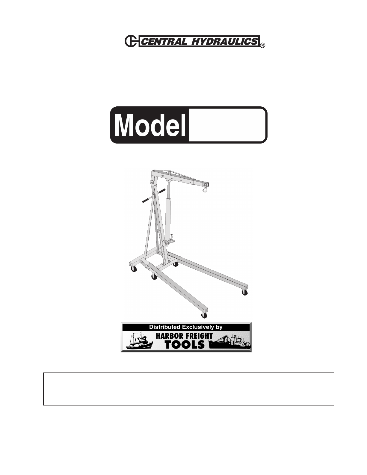
FOLDABLE SHOP CRANE
®
2 TON
46766
ASSEMBLY & OPERATING INSTRUCTIONS
3491 Mission Oaks Blvd., Camarillo, CA 93011
Visit our Web site at http://www.harborfreight.com
TO PREVENT SERIOUS INJURY,
READ AND UNDERSTAND ALL WARNINGS
AND INSTRUCTIONS BEFORE USE.
Copyright© 2002 by Harbor Freight Tools® . All rights reserved. No portion of this manual or any
artwork contained herein may be reproduced in any shape or form without the express written
consent of Harbor Freight Tools.
For technical questions and replacement parts, please call 1-800-444-3353.
REV 05/05
Page 2
THANK YOU for choosing a HARBOR FREIGHT TOOLS product. For future reference, please complete the
owner’s record below:
Model___________ Serial No._____________ Purchase Date_____________
Save This Manual
You will need the manual for the safety warnings and precautions, assembly instructions,
operating and maintenance procedures, parts list and diagram. Keep your invoice with this
manual. Write the invoice number on the inside of the front cover. Keep the manual and
invoice in a safe and dry place for future reference.
Technical Specifications
Product Name: Foldable Shop Crane-2 Ton
Product Number: 46766
Adjust to Heights: 2 T = 42-3/4” H; 1-1/2 T = 49-11/16” H; 1 T = 56-7/8” H
1/2 T = 63-7/8” H
Max Boom Height: 105”
Swivel Hook: 360 Degrees
Dimensions (Folded) 33-1/2” W x 26” L x 66-1/2” H
Dimensions (Unfolded) 35” W x 72” L x 58-3/8” H
Latch: Spring Loaded
Construction: All Steel
Ram: 8 Ton
Weight: 255 LBS
Maximum Capacity: 4,000 LBS
Ram Travel: 19-1/4”
Ground Clearance: 1-1/8”
Front Boom Hook: 7” to Hook opening and 9-1/2” to Hook bottom
Safety Warnings and Precautions
WARNING: When using tool, basic safety precautions should always be followed to
reduce the risk of personal injury and damage to equipment. Read all instructions
before using this tool!
1. Keep work area clean. Cluttered areas invite injuries.
2. Observe work area conditions. Do not use product in damp or wet locations. Don’t expose to rain.
Keep work area well lighted.
3. Keep children away. Children must never be allowed in the work area. Do not let them handle
machines, tools, or extension cords.
4. Store idle equipment. When not in use, products must be stored in a dry location to inhibit rust.
Always lock up products and tools and keep out of reach of children.
5. Do not force product. It will do the job better and more safely at the rate for which it was intended. Do
not use inappropriate attachments in an attempt to exceed the product capacity.
6. Use the right tool for the job. Do not attempt to force a small tool or attachment to do the work of a
larger industrial tool. There are certain applications for which this product was designed. Do not modify
this product and do not use this product for a purpose for which it was not intended.
Sku 46766 For technical questions, please call 1-800-444-3353. Page 2
Page 3

Safety Warnings (cont’d)
7. Dress properly. Do not wear loose clothing or jewelry as they can be caught in moving parts.
Protective, electrically nonconductive clothes and nonskid footwear are recommended when working.
Wear restrictive hair covering to contain long hair.
8. Use eye and ear protection. Always wear ANSI approved impact safety goggles. Wear a full face shield
if you are producing metal filings or wood chips. Wear an ANSI approved dust mask or respirator when
working around metal, wood, and chemical dusts and mists.
9. Do not overreach. Keep proper footing and balance at all times. Do not reach over or across running
machines.
10. Maintain products with care. Keep products clean for better and safer performance. Follow
instructions for lubricating and changing accessories.
11. Remove adjusting keys and wrenches. Check that keys and adjusting wrenches are removed from
the tool or machine work surface before operating.
12. Stay alert. Watch what you are doing, use common sense. Do not operate any tool when you are tired.
13. Check for damaged parts. Before using any product, any part that appears damaged should be
carefully checked to determine that it will operate properly and perform its intended function. Check for
alignment and binding of moving parts; any broken parts or mounting fixtures; and any other condition
that may affect proper operation. Any part that is damaged should be properly repaired or replaced by a
qualified technician.
14. Replacement parts and accessories. When servicing, use only identical replacement parts. Use of
any other parts will void the warranty. Only use accessories intended for use with this tool. Approved
accessories are available from Harbor Freight Tools.
15. Do not operate product if under the influence of alcohol or drugs. Read warning labels on
prescriptions to determine if your judgment or reflexes are impaired while taking drugs. If there is any
doubt, do not operate the tool.
16. Maintenance. For your safety, service and maintenance should be performed regularly by a qualified
technician.
17. Do not exceed the products 4,000 Lb. maximum capacity. Exceeding the maximum capacity may
cause damage to the product and may result in serious harm or injury.
18. Make certain to place the Shop Crane on a flat, sturdy and level surface that is capable of
supporting the weight of the Shop Crane and a 4,000 Lb. Load.
Warning: The warnings, cautions, and instructions discussed in this instruction manual cannot cover
all possible conditions and situations that may occur. It must be understood by the operator that
common sense and caution are factors which cannot be built into this product, but must be supplied
by the operator.
Assembly
Your Foldable Shop Crane will require complete assembly as described in the following steps. To assist you
with assembly and operation please refer to the Operational Figures as well as the Assembly Diagram and
Parts List located on the last pages of this manual.
Warning: Due to the weight of the Shop Crane, assistance during assembly is recommended.
Step 1) Line up the holes in each mid size Caster Wheel (5) with the holes on the Base (4). One mid
size Caster Wheel (5) is to be attached to each side of the Base (4). For each mid size Caster
Wheel (5), slide four (4) Bolts (28) up through a Spring Washer (7) and into Base (4).
REV 11/02; 05/05
Sku 46766 For technical questions, please call 1-800-444-3353. Page 3
Page 4

Line up the holes in each Small Caster (1) with the holes on the Base (4). One Small Caster
(1) is to be attached to each side of the Base (4). For each Small Caster (1), slide four (4)
Bolts (27) up through a Spring Washer (7), and through Washer (6) and into Base (4).
Step 2) Slide each Leg (8 & 25) into each of the two slots on top of the Base (4). Insert two Pins (3)
through the Base (4) at the junction of each Leg (8 and 25). Attach a Hitch Pin (24) through
each of the four (4) Pins (3) to secure together - see Figure 1.
Base (4)
Make certain to set up the Crane
on a flat, stable, level surface.
Hitch Pin (24)
Leg (25)
Pin (3)
Leg (8)
Figure 1-Leg into Base
Step 3) With the assistance of another person, attach the Support Post (10) to the Base (4). Insert
both Bolts (9) down through the bottom bracket of the Support Post (10). Slide on Washers
(32), and slide on Spring Washers (33). Tighten Nuts (18) - see Figure 2.
Grip (36)
Caution: Be aware of dynamic
loading! A sudden start or jerk of
the chain and hook may create for
a brief instant, an excess load,
which may result in damage to the
product and/or personal injury.
(27)
(4)
Support Post (10)
Washers (32)
Spring Washer (33)
Nuts (18)
Figure 2-Support Post to Base
Step 4) Attach both of the Supports (11) to the Base (4), one at each end. For each Support, insert a
Bolt (12) through the hole in the bottom of the Support (11), and through the Base (4). Slide
on Washers (34), Spring Washers (35) and tighten on Nut (2) - see Figure 3 on following
page. Line up the holes at the top of the Support (11) with the second hole down on the
Support Post (10). Attach Supports (11) to the Support Post with Bolt (12). Slide on Washer
(34) and Spring Washer (35). Tighten on Nut (2).
REV 11/02; 05/05
Sku 46766 For technical questions, please call 1-800-444-3353. Page 4
Page 5

Figure 3-Supports to Support Post
Bolt (12)
Nut (2)
Washer (34),
Spring Washer (35)
Supports (11)
Support Post (10)
Nut (2)
Washer (34),
Bolt (12)
Spring Washer (35)
Step 5) Attach the Handle Grip (36) to the Support Post (10). Slide a Washer (6) and a Spring
Washer (7) onto each of four Bolts (27). Insert the Bolt (27) and Washers (6 and 7) through
Handle Grip (36) and tighten to Support Post (10) - see Figure 2.
Step 6) Attach the Hydraulic Ram (21) to the bracket located toward the bottom of the Support Post
(10) - see Figure 4B below. Insert Bolt (17), then slide on Washer (32) and Spring Washer
(33). Tighten on Nut (18). Lean the Hydraulic Ram (21) against the Support Post (10) while
installing the Boom (13) in next step.
Step 7) Set the Boom (13) onto the top of the Support Post (10). Insert Bolt (14) through the holes,
then slide on Washer (30) and Spring Washer (31). Tighten on Nut (26) - see Figure 4A.
Boom (13)
Washers
(32,33)
Nut (18)
Bolt (22)
Nut (26)
Support
Bolt (14)
Washers (32 & 33)
Support Post (10)
Post (10)
Bolt (17)
Nut (18)
Washers
(32,33)
Hydraulic
Ram (21)
Figure 4A -Assembling the Boom
Figure 4B-Attaching the Hydraulic Ram
REV 11/02; 05/05
Sku 46766 For technical questions, please call 1-800-444-3353. Page 5
Page 6

Step 8) Attach the Hydraulic Ram (21) to the fork near the center of the Boom (13) with Bolt (22),
Washer (32) and Spring Washer (33). Tighten into place with Nut (18) - see Figure 4B on the
previous page.
Step 9) Slide the Boom Extension (16) into the Boom (13). Note that there are different settings for
the load. Secure the Boom Extension (16) at the setting
which exceeds the load
you will be
lifting. Insert Bolt (29), Washer (32) and Spring Washer (33) and secure with Nut (18) - see
Figure 5.
Washers (32,33)
Nut (18)
Boom (13)
Bolt (29)
Boom Extension (16)
Figure 5-Assembling the Boom Extension
Step 10) Attach the Hook (19a) around the end of the Boom Extension (16) using Bolt (20). Insert Bolt
(20) through one side of the Hook, through the Boom Extension (16), and out the other side
of the Hook (19a). Slide on Washer (34) and Spring Washer (35). Tighten in place with Nut
(2) - see Figure 6.
Nut (2)
Boom Extension (16)
WARNING:
Never stand under an object that is being
Washers (34 & 35)
lifted by the Shop Crane. Be aware of the
possibility of a load slipping off of the Hook.
An item that falls from the Crane can cause
serious injury.
Bolt (20)
safety latch
Hook (19a)
Figure 6-Attaching the Hook
Step 11) Insert the Jack Handle (23) into the socket on the Hydraulic Ram (21).
Operation
Step 1) Set the Boom Extension (16) to a weight limit setting that exceeds the weight you will be
lifting. Do not exceed the Maximum 2 Ton weight capacity. Insert Bolt (29), Washer (32) and
Spring Washer (33) and secure with Nut (18) - see Figure 5.
Step 2) Test the operation of the Shop Crane prior to lifting the load. Make certain that pumping the
Handle will raise a load. Verify that all hardware is tight and in good working order.
Step 3) Move the Crane so that the Hook (19) is directly above the item to be lifted. M ake certain that
the safety latch on the Hook (19) fully closes. Securely attach the Hook (19) to the item.
Load must be secure in the Hook (19) with the safety latch fully closed. Make certain that the
load is sustained with chains or slings before using the Crane to lift it.
REV 05/05; 09/07
Sku 46766 For technical questions, please call 1-800-444-3353. Page 6
Page 7

Operation (cont’d)
CAUTION!
Limit movement of the Shop Crane when under load. Always lower the load as low as possible to reduce
the center of gravity. DANGER! If the load is not lowered and is allowed to swing freely, the Shop
Crane can tip over.
Step 4) To raise the Boom (13), turn the Hydraulic Ram’s release valve fully clockwise. Pump the
Handle (23) up and down repeatedly until the item is lifted to the desired height.
Step 5) To lower the Crane, slowly turn the release valve counterclockwise.
Folding the Shop Crane
Step 1) Lower the Crane all the way.
Step 2) Remove the front two Pins (3). Leave rear Pins (3) in place.
Step 3) Raise the Legs (8 & 25) until they rest against the Support Post (10).
Step 4) Set the loose Pins (3) into the middle hole in the Base.
Note: When folded up, the Shop Crane can be rolled on the 2 small Casters and 2 mid size Casters.
Troubleshooting Tips
PROBLEM SOLUTION
Hydraulic Ram will not lift load
Will not hold load/ Handle rises
Will not lift to its full height
Will not lower completely
Feels spongy; will not lift smoothly
••
• Release valve not closed. Turn valve clockwise.
••
••
• Check Hydraulic fluid level
••
••
• Pump seal and backup ring defective. Have serviced by
••
a qualified technician.
••
• Discharge ball is not sealing hydraulic system.
••
Hydraulic fluid may be dirty.
••
• Open Release Valve and then pump the Handle.
••
••
• Flush system.
••
Bleeding Instructions:
••
• Check Hydraulic fluid level.
••
••
• Air in Hydraulic system. Open Release valve, pump
••
handle four full strokes to release air.
••
• Top off with Hydraulic Fluid. Close the oil fill cap. Close
••
Release V alve.
••
• Return Spring broken or linkages binding. Grease pivot
••
shaft; oil all linkages.
••
• Have qualified technician replace Return Spring
••
Bleeding Instructions:
••
• Check Hydraulic fluid level.
••
••
• Air in Hydraulic system. Open Release valve, pump
••
handle four full strokes to release air.
••
• Top off with Hydraulic Fluid. Close the oil fill cap. Close
••
Release V alve.
REV 11/02; 04/03
Sku 46766 For technical questions, please call 1-800-444-3353. Page 7
Page 8

Unpacking
PLEASE READ THE FOLLOWING CAREFULLY
THE MANUFACTURER AND/OR DISTRIBUTOR HAS PROVIDED THE PARTS DIAGRAM IN THIS
MANUAL AS A REFERENCE TOOL ONLY. NEITHER THE MANUFACTURER NOR DISTRIBUT OR MAKES
ANY REPRESENT ATION OR WARRANTY OF ANY KIND T O THE BUYER THAT HE OR SHE IS QU ALIFIED
TO MAKE ANY REPAIRS TO THE PRODUCT OR THAT HE OR SHE IS QUALIFIED TO REPLACE ANY
P ARTS OF THE PRODUCT. IN F A CT , THE MANUF ACTURER AND/OR DISTRIB UTOR EXPRESSLY ST A TES
THAT ALL REPAIRS AND PARTS REPLACEMENTS SHOULD BE UNDERTAKEN BY CERTIFIED AND
LICENSED TECHNICIANS AND NOT BY THE BUYER. THE BUYER ASSUMES ALL RISK AND LIABILITY
ARISING OUT OF HIS OR HER REPAIRS TO THE ORIGINAL PRODUCT OR REPLACEMENT PARTS
THERETO, OR ARISING OUT OF HIS OR HER INSTALLATION OF REPLACEMENT PARTS THERETO.
When unpacking your 2 Ton Foldable Shop Crane, check to make sure the following parts are included. If any
parts are missing or broken, please call HARBOR FREIGHT TOOLS at 1-800-444-3353.
Parts List
traPnoitpircseDytQtraPnoitpircseDytQ
1.aiD”63.2-retsaCllamS202"43.3x41MtloB1
241MtuN412maRciluardyH1
3niP422"43.3x61MtloB )e
4esaB132eldnaHkcaJ1
5.aiD”45.3-retsaCeziSdiM442niPhctiH4
6rehsaW2152geLtfeL1
7rehsaWgnirpS826281MtuN1
8geLthgiR172"95.x8
9"47.3x61MtloB282"87.x8MtloB61
01tsoPtroppuS192"43.3x61MtloB1
11troppuS20381MrehsaW1
21"31.4x41MtloB31381MrehsaWgnirp
31mooB12361MrehsaW5
41"31.4x81MtloB13361MrehsaWgnirpS5
51 -desunu- 4341MrehsaW4
61noisnetxEmooB15341MrehsaWgnirpS4
71"47.3x6
8161MtuN573 -desunu-
a91kooH1
1MtloB )edarG8.8( 163pirGeldnaH1
MtloB21
S1
darG8.8( 1
Note: Some parts are listed and shown for illustration purposes only and are not available individually as
replacement part s.
Sku 46766 For technical questions, please call 1-800-444-3353. Page 8
REV 11/02; 05/05
Page 9

Parts/Assembly Diagram
Make certain to set up the Crane on
a flat, stable, level surface.
REV 11/02; 05/05
Sku 46766 For technical questions, please call 1-800-444-3353. Page 9
 Loading...