

Page 1
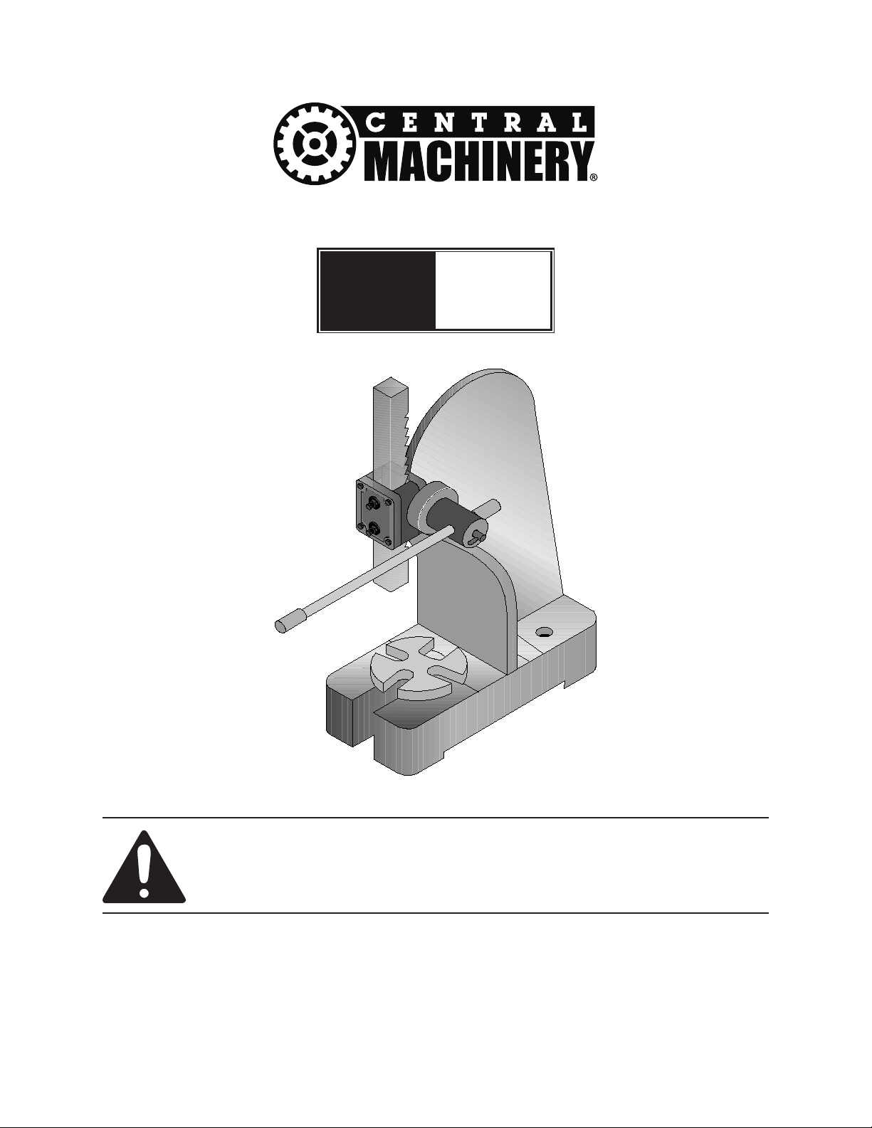
ARBOR PRESS
03551
Model
03552
SET UP AND OPERATING INSTRUCTIONS
Visit our website at: http://www.harborfreight.com
Read this material before using this product.
Failure to do so can result in serious injury.
SAVE THIS MANUAL.
Copyright© 1997 by Harbor Freight Tools®. All rights reserved. No portion of this manual or any artwork
contained herein may be reproduced in any shape or form without the express written consent of
Harbor Freight Tools. Diagrams within this manual may not be drawn proportionally. Due to continuing
improvements, actual product may differ slightly from the product described herein. Tools required for
assembly and service may not be included.
For technical questions or replacement parts, please call 1-800-444-3353.
Manual Revised 10i
Page 2

SPECIFICATIONS
3551 3552
Capacity 1/2 Ton 1 Ton
Maximum Height 4-1/2” 5-1/2”
Maximum Diameter 6-1/2” 8”
Largest Arbor 1” 1-1/8”
Ram Square 3/4” 1”
Height of Press 10” 13”
Base Dimensions 4” x 9-1/2” 5” x 11”
Leverage Ratio 20:1 20: 1
Save this manual
You will need the manual for the safety
warnings and cautions, assembly instructions,
operating procedures, maintenance
procedures, trouble shooting, parts list,
and diagram. Keep your invoice with this
manual. Write the invoice number on the
inside of the front cover. Keep both this
manual and your invoice in a safe, dry place
for future reference.
SAFETY WARNING &
CAUTIONS
not let them handle machines, tools, or
extension cords.
STORE IDLE EQUIPMENT.4. When not
in use, tools must be locked up in a dry
location to inhibit rust. Always lock up
tools and keep out of reach of children.
DO NOT FORCE THE TOOL.5. It will do
the job better and more safely at the rate
for which it was intended. Do not use
inappropriate attachments in an attempt
to exceed the tool’s capacities.
USE THE RIGHT TOOL FOR THE JOB. 6.
Do not attempt to force a small tool or
attachment to do the work of a larger
industrial tool. Do not use a tool for a
purpose for which it was not intended.
DRESS PROPERLY.7. Do not wear loose
clothing or jewelry as they can be caught
in moving parts. Protective, electrically
non-conductive clothes and non-skid
footwear are recommended when
working. Wear restrictive hair covering to
contain long hair.
WARNING: When using electric tools,
machines, or equipment, basic safety
precautions should always be followed
to reduce the risk of re, electric
shock, and personal injury. READ ALL
INSTRUCTIONS BEFORE USING THIS
TOOL!
KEEP WORK AREA CLEAN.1. Cluttered
areas invite injuries.
OBSERVE WORK AREA CONDITIONS.2.
Do not use machines or power tools in
damp, wet, or poorly lit locations. Don’t
expose to rain. Keep work area well lit.
Do not use electrically powered tools
in the presence of ammable gases or
liquids.
KEEP CHILDREN AWAY.3. Children must
never be allowed in the work area. Do
USE EYE AND EAR PROTECTION.8.
Always wear ANSI approved chemical
splash goggles when working with
chemicals. Always wear ANSI approved
impact safety goggles at other times.
Wear a full face shield if you are
producing metal lings or wood chips.
Wear an ANSI approved dust mask or
respirator when working around metal,
wood, and chemical dusts and mists.
DO NOT ABUSE THE POWER CORD.9.
Do not yank it to disconnect it from the
receptacle. Do not carry tools by the
cord.
DO NOT OVERREACH.10. Keep proper
footing and balance at all times. Do not
reach over or across running machines.
Page 2For technical questions, please call 1-800-444-3353.SKU 03551 03552
Page 3

MAINTAIN TOOLS WITH CARE.11. Keep
tools sharp and clean for better and
safer performance. Follow instructions
for lubricating and changing accessories.
Inspect tool cords periodically and, if
damaged, have them repaired by an
authorized technician. The handles must
be kept clean, dry, and free from oil and
grease at all times.
damaged should be properly repaired
or replaced by a qualied technician. Do
not use the tool if any switch does not
turn on and off properly.
GUARD AGAINST ELECTRIC SHOCK.18.
Prevent body contact with grounded
surfaces such as pipes, radiators,
ranges, and refrigerator enclosures.
DISCONNECT POWER.12. Unplug when
not in use, before servicing, and when
changing accessories.
REMOVE ADJUSTING KEYS AND 13.
WRENCHES. Make it a habit to check
that keys and adjusting wrenches are
removed from the tool or machine work
surface before plugging it in.
AVOID UNINTENTIONAL STARTING.14.
Be sure the switch is in the OFF position
when not in use and before plugging in.
Do not carry any tool with your nger on
the trigger, whether it is plugged in or
not.
OUTDOOR EXTENSIONS CORDS. 15.
When the equipment is operated
outdoors, use only extension cords
intended for outside use. See chart
under “Extension Cords" for the proper
AWG rating depending on the length of
the cord(s) being used.
STAY ALERT. 16. Watch what you are
doing; use common sense. Do not
operate any tool when you are tired.
REPLACEMENT PARTS AND 19.
ACCESSORIES. When servicing, use
only identical replacement parts. Use of
any other parts will void the warranty.
Only use accessories intended for use
with this tool. Approved accessories are
available from Harbor Freight Tools.
DO NOT OPERATE TOOL IF UNDER 20.
THE INFLUENCE OF ALCOHOL
OR DRUGS. Read warning labels
on prescriptions to determine if your
judgment or reexes are impaired while
taking drugs. If there is any doubt, do not
operate the tool.
UNPACKING
If any parts are missing or broken,
please call Harbor Freight Tools at the number
on the cover of this manual.
Part Description Qty
1 Body 1
N/A Handle Assembly 1
6 Plate 1
10 Rack 1
CHECK DAMAGED PARTS.17. Before
using any tool, any part that appears
damaged should be carefully checked
to determine that it will operate properly
and perform its intended function. Check
for alignment and binding of moving
parts; any broken parts or mounting
xtures; and any other condition that may
affect proper operation. Any part that is
Page 3For technical questions, please call 1-800-444-3353.SKU 03551 03552
Page 4

ASSEMBLY
Body (#1)
Mounting Hole
Mounting Hole
(not shown)
Plate (#6)
Body (#1)
Spring Pin (#7)
(not shown)
Rack (#10)
Rack Teeth
Body (#1)
Cover (#8)
Mounting the Body to Your
Workbench
Select a place on your workbench to 1.
mount the Arbor Press.
Purchase hardware to mount your Arbor 2.
Press to your workbench. Bolt length
will be the thickness of your workbench
plus 2-1/2” of length for the Arbor Press
BODY (#1).
Arbor Press Assembly
Figure 2 -- Installing the Plate
1. Place the PLATE (#6) onto the Base of
the BODY (#1) as shown in Figure 2.
Insert the SPRING PIN (#7) into the hole
in the BODY.
Figure 1 -- Location of Mounting Holes
3. Use the two mounting holes in the BODY
of the Arbor Press as a template as
shown in Figure 1. Mark and Drill holes
in your workbench.
Place the BODY over the holes in the 4.
workbench and insert the bolts through
the holes. Thread on the nuts and
tighten.
Figure 3 -- Installing the Rack
2. Insert the RACK (#10) down through the top
of the BODY as shown in Figure 3. Make
sure the teeth of the RACK are towards the
rear of the BODY as shown in the Figure.
Page 4For technical questions, please call 1-800-444-3353.SKU 03551 03552
Page 5

Unwrap the Handle Assembly and discard 3.
Handle Assembly
Body (#1)
Rack (#10)
Ring (#5)
Handle Assembly
the protective padding.
Figure 4 -- Installing the Handle Assembly
4. Insert the GEAR (#14) section of the Handle
Assembly into the side of the Arbor Press as
shown in Figure 4. The GEAR will only t
into the side shown in the Figure.
Your Arbor Press is ready for use.7.
6. Slide the RING (#5) onto the protruding end
You may have to rotate the Handle Assembly 5.
slightly to get the teeth of the GEAR to mesh
with the teeth of the RACK.
Figure 5 -- Attaching the Ring
of the GEAR as shown in Figure 5. Tighten
the SCREW (#4) on the RING to secure the
GEAR and Handle Assembly.
Page 5For technical questions, please call 1-800-444-3353.SKU 03551 03552
Page 6

OPERATION
Lock Pin (#11)
Shaft (#15)
Shaft (#15)
Rack (#10)
Plate (#6)
Adjusting the Handle Assembly
Determine if you will need a moderate or 1.
large amount of leverage for the job.
Using the Arbor Press
Figure 7 -- Raising the Rack
Figure 6 -- Adjusting the Shaft
2. Loosen the LOCK PIN (#11) by turning it
as shown in Figure 6. This will allow you
to adjust the length of the SHAFT (#15).
Adjust the length of the SHAFT to 3.
suit your needs. If a large amount of
leverage is needed for your press job,
lock the SHAFT in the extended position.
If a moderate amount of leverage is
needed, position the SHAFT in the
middle of the GEAR.
Tighten the LOCK PIN to secure the 4.
Handle Assembly.
The following Steps show the SHAFT in
the extended position.
1. Raise the RACK (#10) up by turning the
Handle Assembly as shown in Figure 7.
Turn the PLATE (#6) until the appropriate 2.
width opening is centered under the
RACK. The appropriate width depends
upon what you are using the press for.
If you do not want an opening beneath
the RACK, rotate the PLATE until one
of the four solid parts of the PLATE is
underneath the RACK.
Place the part you need to press onto 3.
the PLATE.
Turn the Handle Assembly to lower the 4.
RACK until the top of the RACK contacts
the press part.
Place downward pressure on the Handle 5.
Assembly to press the part as needed.
Release pressure on the Handle 6.
Assembly and raise the RACK to remove
the part.
Page 6For technical questions, please call 1-800-444-3353.SKU 03551 03552
Page 7

PARTS LIST AND ASSEMBLY DIAGRAM
Part Description Qty
1 Body 1
2 Bolt 8
3 Nut 6
4 Screw 1
5 Ring 1
6 Plate 1
Part Description Qty
7 Spring Pin 1
8 Cover 1
9 Washer 1
10 Rack 1
11 Lock Pin 1
12 Pin 1
Part Description Qty
13 Screw 1
14 Gear 1
15 Shaft 1
16 Handle 2
Page 7For technical questions, please call 1-800-444-3353.SKU 03551 03552
Page 8

LIMITED 90 DAY WARRANTY
Harbor Freight Tools Co. makes every effort to assure that its products meet high quality and
durability standards, and warrants to the original purchaser that this product is free from defects
in materials and workmanship for the period of 90 days from the date of purchase. This warranty
does not apply to damage due directly or indirectly, to misuse, abuse, negligence or accidents,
repairs or alterations outside our facilities, criminal activity, improper installation, normal wear
and tear, or to lack of maintenance. We shall in no event be liable for death, injuries to persons
or property, or for incidental, contingent, special or consequential damages arising from the use
of our product. Some states do not allow the exclusion or limitation of incidental or consequential
damages, so the above limitation of exclusion may not apply to you. THIS WARRANTY IS
EXPRESSLY IN LIEU OF ALL OTHER WARRANTIES, EXPRESS OR IMPLIED, INCLUDING
THE WARRANTIES OF MERCHANTABILITY AND FITNESS.
To take advantage of this warranty, the product or part must be returned to us with
transportation charges prepaid. Proof of purchase date and an explanation of the complaint must
accompany the merchandise. If our inspection veries the defect, we will either repair or replace
the product at our election or we may elect to refund the purchase price if we cannot readily and
quickly provide you with a replacement. We will return repaired products at our expense, but if
we determine there is no defect, or that the defect resulted from causes not within the scope of
our warranty, then you must bear the cost of returning the product.
This warranty gives you specic legal rights and you may also have other rights which vary
from state to state.
3491 Mission Oaks Blvd. • PO Box 6009 • Camarillo, CA 93011 • (800) 444-3353
Page 8For technical questions, please call 1-800-444-3353.SKU 03551 03552
 Loading...