

Page 1
5 TON PULL-BACK RAM
Model
33611
®
ASSEMBLY AND OPERATION INSTRUCTIONS
Due to continuing improvements, actual product may differ slightly from the product described herein.
For technical questions or replacement parts, please call 1-800-444-3353.
3491 Mission Oaks Blvd., Camarillo, CA 93011
Visit our website at: http://www.harborfreight.com
TO PREVENT SERIOUS INJURY, READ AND UNDERSTAND
ALL WARNINGS AND INSTRUCTIONS BEFORE USE.
Copyright© 1997, 2007 by Harbor Freight Tools®. All rights reserved. No portion
of this manual or any artwork contained herein may be reproduced in any shape
or form without the express written consent of Harbor Freight Tools.
Manual Revised 02/07
Page 2

SAVE THIS MANUAL
You will need this manual for the safety instructions, assembly and operating instructions
and parts list. Put it in a safe, dry place for future reference. Keep your invoice with
this manual. Write the invoice number on the inside front cover.
SAFETY WARNINGS & CAUTIONS
1. KEEP WORK AREA CLEAN. Cluttered areas invite injuries.
2. KEEP CHILDREN AWAY. All children should be kept away from the work area.
Don’t let them handle the tool.
3. DO NOT ASSEMBLE OR OPERATE THIS TOOL IF UNDER THE INFLUENCE
OF ALCOHOL OR DRUGS. Read warning labels on prescriptions to determine
if your judgment or reflexes are impaired while taking drugs. If there is any
doubt, do not attempt to assemble or operate.
4. AVOID MOVING PARTS WHILE USING THE PULL-BACK RAM. Once unit is
set in place keep fingers and hands away from contact areas. If unit needs to
be moved, release pump pressure, move, and resume pumping.
5. USE EYE PROTECTION. Wear ANSI approved impact safety goggles.
Goggles are available from Harbor Freight Tools.
6. DRESS SAFELY. Protective gloves and non-skid footwear or safety shoes are
recommended when working with and operating the Pull Back Ram. Don’t wear
loose clothing or jewelry. They can get caught in moving parts. Also, wear a
protective hair covering to prevent long hair from getting caught in the Pull Back
Ram .
7. DON’T OVERREACH. Keep proper footing and balance at all times.
8. STAY ALERT. Watch what you are doing. Use common sense. Do not operate
any tool when you are tired.
9. 10,000 LB. LIMIT. Do not operate beyond rated capacity.
10. REPLACEMENT PARTS AND ACCESSORIES. When servicing, use only
identical replacement parts. Only use accessories intended for use with the Pull
Back Ram. Approved accessories are available from Harbor Freight Tools.
11. STORE IDLE EQUIPMENT. When not in use, the Pull Back Ram should be
stored in a dry location to reduce rust. For safety, store the Pull Back Ram in
a locked cabinet, out of reach of children. During long term storage, coat the
exposed chrome area of the Ram with a protective lubricant (such as silicon
spray) to prevent rust damage
12. KEEP COUPLER VALVES PROTECTED WHEN NOT IN USE. Dust caps are
included for all coupler valves and should be screwed in when not in use to
keep the equipment clean.
SKU 33611 For technical questions, please call 1-800-444-3353. Page 2
Page 3
UNPACKING
When unpacking your Pull-Back Ram, check to make sure the following parts are included.
If any parts are missing or broken, please call Harbor Freight Tools at the number on the
cover of this manual.
Item # Description Qty
1 Pull-Back Ram 1
2 End Plug 1
3 Female End Hook (attached to Ram) 1
4 Male End Hook (attached to Ram) 1
OVERVIEW
Your Pull Back Ram is designed for pulling up to 10,000 pounds. Never exceed the maximum
weight for the Pull-Back Ram as it may damage the equipment and cause serious injury.
Your Pull-Back Ram is designed to be used with a hydraulic pump that and hydraulic hose
may be purchased separately from Harbor Freight.
ASSEMBLY
PULL-BACK RAM and HYDRAULIC PUMP Assembly
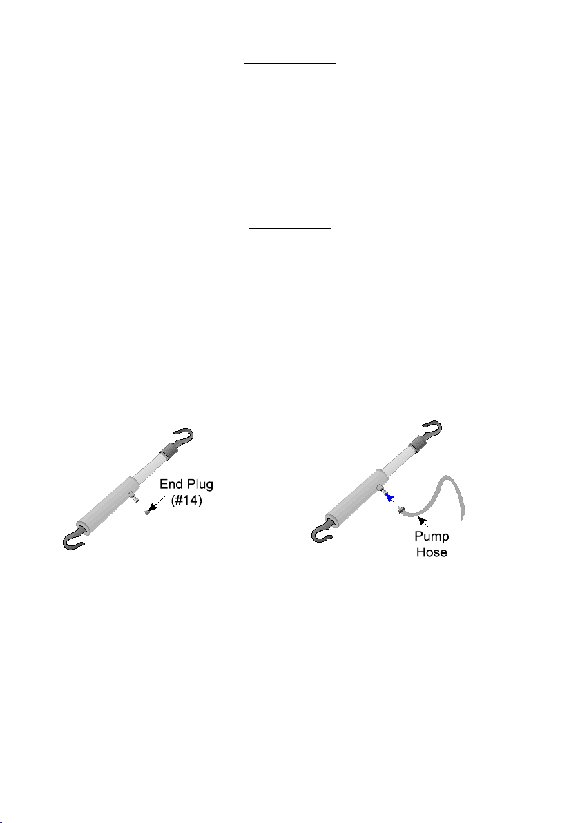
Step 1: Unscrew and save the END PLUG (#14) located on the end of the Pull-Back
Ram COUPLER (#16) as shown in Figure 1.
Figure 1 — Removing End Plug Figure 2 — Connecting Hose
Step 2: Securely screw the Hydraulic Pump Hose (not included) into the Pull Back Ram
COUPLER as shown in Figure 2.
Step 3: Refer to the Hydraulic Pump instruction manual for pump assembly instructions.
SKU 33611 For technical questions, please call 1-800-444-3353. Page 3
Page 4

OPERATION
General Operation
The PULL-BACK RAM may be used in either a horizontal or a vertical position. Its
HOOKS (#3,#4) will turn to accept hooking from different angles.
Refer to the Hydraulic Pump instruction manual for pump operation.
Step 1: Position the Hydraulic Pump on a stable surface close to the pulling area.
Step 2: Hook one end of the Pull-Back Ram to the object to be moved and the other
end to a stable base as shown in Figure 3. A chain or strap may be used on
either side to provide a hooking surface. Make sure the chain or strap is rated
to support the pulling weight.
Figure 3 — Connecting Chain and Strap
Step 3: Slowly provide pressure to the Pull-Back Ram. Use caution; watch for damage
to stressed areas and ensure personal safety at all times.
Step 4: When the object has reached the desired position, make sure it is stable and
slowly release pressure to the Pull-Back Ram. If the object is not stable, affix it
in place before releasing pressure to the Pull-Back Ram.
SKU 33611 For technical questions, please call 1-800-444-3353. Page 4
Page 5

CARE AND MAINTENANCE
Keep all moving parts well lubricated. Using a high quality lubricating oil, coat the
1.
RAM (#23) before every use.
Occasionally the RAM will need to be purged of air (bled). The symptoms will
2.
include: slow response to pumping, a spongy feeling to pumping, the RAM not
compressing as far as it should, and a loss of pulling power. Bleeding the ram
requires specialized tools and procedures. Only a qualified technician should bleed
the
LIMITED 90 DAY WARRANTY
Harbor Freight Tools Co. makes every effort to assure that its products meet high quality and durability
standards, and warrants to the original purchaser that this product is free from defects in materials and
workmanship for the period of ninety days from the date of purchase. This warranty does not apply to damage
due directly or indirectly, to misuse, abuse, negligence or accidents, repairs or alterations outside our facilities,
or to lack of maintenance. We shall in no event be liable for death, injuries to persons or property, or for
incidental, contingent, special or consequential damages arising from the use of our product. Some states
do not allow the exclusion or limitation of incidental or consequential damages, so the above limitation of
exclusion may not apply to you. THIS WARRANTY IS EXPRESSLY IN LIEU OF ALL OTHER WARRANTIES,
EXPRESS OR IMPLIED, INCLUDING THE WARRANTIES OF MERCHANTABILITY AND FITNESS.
To take advantage of this warranty, the product or part must be returned to us with transportation charges
prepaid. Proof of purchase date and an explanation of the complaint must accompany the merchandise. If
our inspection verifies the defect, we will either repair or replace the product at our election or we may elect
to refund the purchase price if we cannot readily and quickly provide you with a replacement. We will return
repaired products at our expense, but if we determine there is no defect, or that the defect resulted from
causes not within the scope of our warranty, then you must bear the cost of returning the product.
This warranty gives you specific legal rights and you may also have other rights which vary from state to
state.
3491 Mission Oaks Blvd. • PO Box 6009 • Camarillo, CA 93011 • (800) 444-3353
SKU 33611 For technical questions, please call 1-800-444-3353. Page 5
Page 6

PARTS LIST
Part Description Q’ty
1
Up-Hook 1
2
Nut 1
3
Hex Screw 1
4
Spring 1
5
Shaft 1
6
Nut 1
7
O-Ring 1
8
O-Ring 2
9
Spindle Screw 1
10
Spring 1
11
Valve 1
12
Oil Ring 1
13
O-Ring 1
14
End Plug
Part Description Q’ty
15
Connection Nut
16
Coupler
17
Bushing
18
Retaining Ring
19
O-Ring
20
U-Type Packing
21
Collar
22
Nut
23
Ram
24
Cylinder
25
Down Hook
1
PLEASE READ THE FOLLOWING CAREFULLY
THE MANUFACTURER AND/OR DISTRIBUTOR HAS PROVIDED THE PARTS LIST AND
ASSEMBLY DIAGRAM IN THIS MANUAL AS A REFERENCE TOOL ONLY. NEITHER THE
MANUFACTURER OR DISTRIBUTOR MAKES ANY REPRESENTATION OR WARRANTY
OF ANY KIND TO THE BUYER THAT HE OR SHE IS QUALIFIED TO MAKE ANY REPAIRS
TO THE PRODUCT, OR THAT HE OR SHE IS QUALIFIED TO REPLACE ANY PARTS OF
THE PRODUCT. IN FACT, THE MANUFACTURER AND/OR DISTRIBUTOR EXPRESSLY
STATES THAT ALL REPAIRS AND PARTS REPLACEMENTS SHOULD BE UNDERTAKEN
BY CERTIFIED AND LICENSED TECHNICIANS, AND NOT BY THE BUYER. THE BUYER
ASSUMES ALL RISK AND LIABILITY ARISING OUT OF HIS OR HER REPAIRS TO THE
ORIGINAL PRODUCT OR REPLACEMENT PARTS THERETO, OR ARISING OUT OF HIS
OR HER INSTALLATION OF REPLACEMENT PARTS THERETO.
1
1
1
1
1
1
1
1
1
1
1
SKU 33611 For technical questions, please call 1-800-444-3353. Page 6
Page 7

Record Product’s Serial Number Here:
Note: If product has no serial number, record month and year of purchase instead.
Note: Some parts are listed and shown for illustration purposes only, and are not available individually as replace-
ment parts.
DIAGRAM
SKU 33611 For technical questions, please call 1-800-444-3353. Page 7
 Loading...