

Page 1
INDUSTRIAL
14” CUT-OFF SAW
1624
SET UP AND OPERATING INSTRUCTIONS
Distributed exclusively by Harbor Freight Tools®.
3491 Mission Oaks Blvd., Camarillo, CA 93011
Visit our website at: http://www.harborfreight.com
Read this material before using this product.
Failure to do so can result in serious injury.
SAVE THIS MANUAL.
Copyright© 1997 by Harbor Freight Tools®. All rights reserved. No portion of this manual or any artwork
contained herein may be reproduced in any shape or form without the express written consent of
Harbor Freight Tools. Diagrams within this manual may not be drawn proportionally. Due to continuing
improvements, actual product may differ slightly from the product described herein. Tools required for
assembly and service may not be included.
For technical questions or replacement parts, please call 1-800-444-3353.
Manual Revised 09c
Page 2

SAVE THIS MANUAL
Keep this manual for the safety warnings and precautions, assembly, operating, inspection, maintenance and cleaning
procedures. Write the product’s serial
number in the back of the manual near the
assembly diagram (or month and year of
purchase if product has no number). Keep
this manual and the receipt in a safe and
dry place for future reference.
IMPORTANT SAFETY
INFORMATION
In this manual, on the labeling,
and all other information provided with this product:
This is the safety alert
symbol. It is used to alert
you to potential personal
injury hazards. Obey all
safety messages that
follow this symbol to avoid
possible injury or death.
NOTICE is used to
address practices
not related to personal injury.
CAUTION, without
the safety alert
symbol, is used to address
practices not related to
personal injury.
General Tool Safety Warnings
WARNING Read all safety
warnings and instructions.
Failure to follow the warnings and
instructions may result in electric
shock, re and/or serious injury.
Save all warnings and
instructions for future reference.
KEEP GUARDS IN PLACE and in 1.
working order.
REMOVE ADJUSTING KEYS AND 2.
WRENCHES. Form habit of checking to see that keys and adjusting
wrenches are removed from tool
before turning it on.
DANGER indicates
a hazardous
situation which, if not
avoided, will result in death or
serious injury.
WARNING
indicates a
hazardous situation which, if
not avoided, could result in
death or serious injury.
CAUTION, used
with the safety
alert symbol, indicates a
hazardous situation which, if
not avoided, could result in
minor or moderate injury.
SKU 1624 For technical questions, please call 1-800-444-3353. Page 2
KEEP WORK AREA CLEAN. Clut-3.
tered areas and benches invite accidents.
DON’T USE IN DANGEROUS EN-4.
VIRONMENT. Don’t use power tools
in damp or wet locations, or expose
them to rain. Keep work area well
lighted.
KEEP CHILDREN AWAY. All visitors 5.
should be kept safe distance from
work area.
MAKE WORKSHOP KID PROOF 6.
with padlocks, master switches, or by
removing starter keys.
Page 3

DON’T FORCE TOOL. It will do the 7.
job better and safer at the rate for
which it was designed.
USE RIGHT TOOL. Don’t force tool 8.
or attachment to do a job for which it
was not designed.
glasses only have impact resistant
lenses, they are NOT safety glasses.
SECURE WORK. Use clamps or a 12.
vise to hold work when practical. It’s
safer than using your hand and it
frees both hands to operate tool.
RECOMMENDED MINIMUM WIRE
GAUGE FOR EXTENSION CORDS
(120 VOLT)
NAMEPLATE
AMPERES
(at full load)
0 – 6 18 16 16 14
6.1 – 10 18 16 14 12
10.1 – 12 16 16 14 12
12.1 – 16 14 12 Do not use.
EXTENSION CORD
LENGTH
25’ 50’ 100’ 150’
TABLE A
USE PROPER EXTENSION CORD. 9.
Make sure your extension cord is
in good condition. When using an
extension cord, be sure to use one
heavy enough to carry the current
your product will draw. An undersized
cord will cause a drop in line voltage
resulting in loss of power and overheating. Table A shows the correct
size to use depending on cord length
and nameplate ampere rating. If in
doubt, use the next heavier gauge.
The smaller the gauge number, the
heavier the cord.
WEAR PROPER APPAREL. Do not 10.
wear loose clothing, gloves, neckties, rings, bracelets, or other jewelry
which may get caught in moving
parts. Nonslip footwear is recommended. Wear protective hair covering to contain long hair.
ALWAYS USE SAFETY GLASSES. 11.
Also use face or dust mask if cutting
operation is dusty. Everyday eye-
DON’T OVERREACH. Keep proper 13.
footing and balance at all times.
MAINTAIN TOOLS WITH CARE. 14.
Keep tools sharp and clean for best
and safest performance. Follow
instructions for lubricating and changing accessories.
DISCONNECT TOOLS before ser-15.
vicing; when changing accessories,
such as blades, bits, cutters, and the
like.
REDUCE THE RISK OF UNINTEN-16.
TIONAL STARTING. Make sure
switch is in off position before plugging in.
USE RECOMMENDED ACCESSO-17.
RIES. Consult the owner’s manual for
recommended accessories. The use
of improper accessories may cause
risk of injury to persons.
NEVER STAND ON TOOL. Serious 18.
injury could occur if the tool is tipped
or if the cutting tool is unintentionally
contacted.
CHECK DAMAGED PARTS. Before 19.
further use of the tool, a guard or
other part that is damaged should
be carefully checked to determine
that it will operate properly and perform its intended function – check for
alignment of moving parts, binding
of moving parts, breakage of parts,
mounting, and any other conditions
that may affect its operation. A guard
SKU 1624 For technical questions, please call 1-800-444-3353. Page 3
Page 4
or other part that is damaged should
be properly repaired or replaced.
DIRECTION OF FEED. Feed work 20.
into a blade or cutter against the
direction of rotation of the blade or
cutter only.
NEVER LEAVE TOOL RUNNING 21.
UNATTENDED. TURN POWER OFF.
Don’t leave tool until it comes to a
complete stop.
GROUNDING INSTRUCTIONS
conductor with insulation having an
outer surface that is green with or
without yellow stripes is the equipment-grounding conductor. If repair
or replacement of the electric cord or
plug is necessary, do not connect the
equipment-grounding conductor to a
live terminal.
Check with a qualied electrician or 4.
service personnel if the grounding
instructions are not completely understood, or if in doubt as to whether the
tool is properly grounded.
TO PREVENT
ELECTRIC SHOCK
AND DEATH FROM
INCORRECT GROUNDING
WIRE CONNECTION
READ AND FOLLOW THESE
INSTRUCTIONS:
110-120 V~ Grounded Tools: Tools
with Three Prong Plugs
In the event of a malfunction or 1.
breakdown, grounding provides a
path of least resistance for electric
current to reduce the risk of electric
shock. This tool is equipped with an
electric cord having an equipmentgrounding conductor and a grounding plug. The plug must be plugged
into a matching outlet that is properly
installed and grounded in accordance
with all local codes and ordinances.
Do not modify the plug provided – if it 2.
will not t the outlet, have the proper
outlet installed by a qualied electri-
cian.
Improper connection of the equip-3.
ment-grounding conductor can result in a risk of electric shock. The
Use only 3-wire extension cords that 5.
have 3-prong grounding plugs and
3-pole receptacles that accept the
tool’s plug.
Repair or replace damaged or worn 6.
cord immediately.
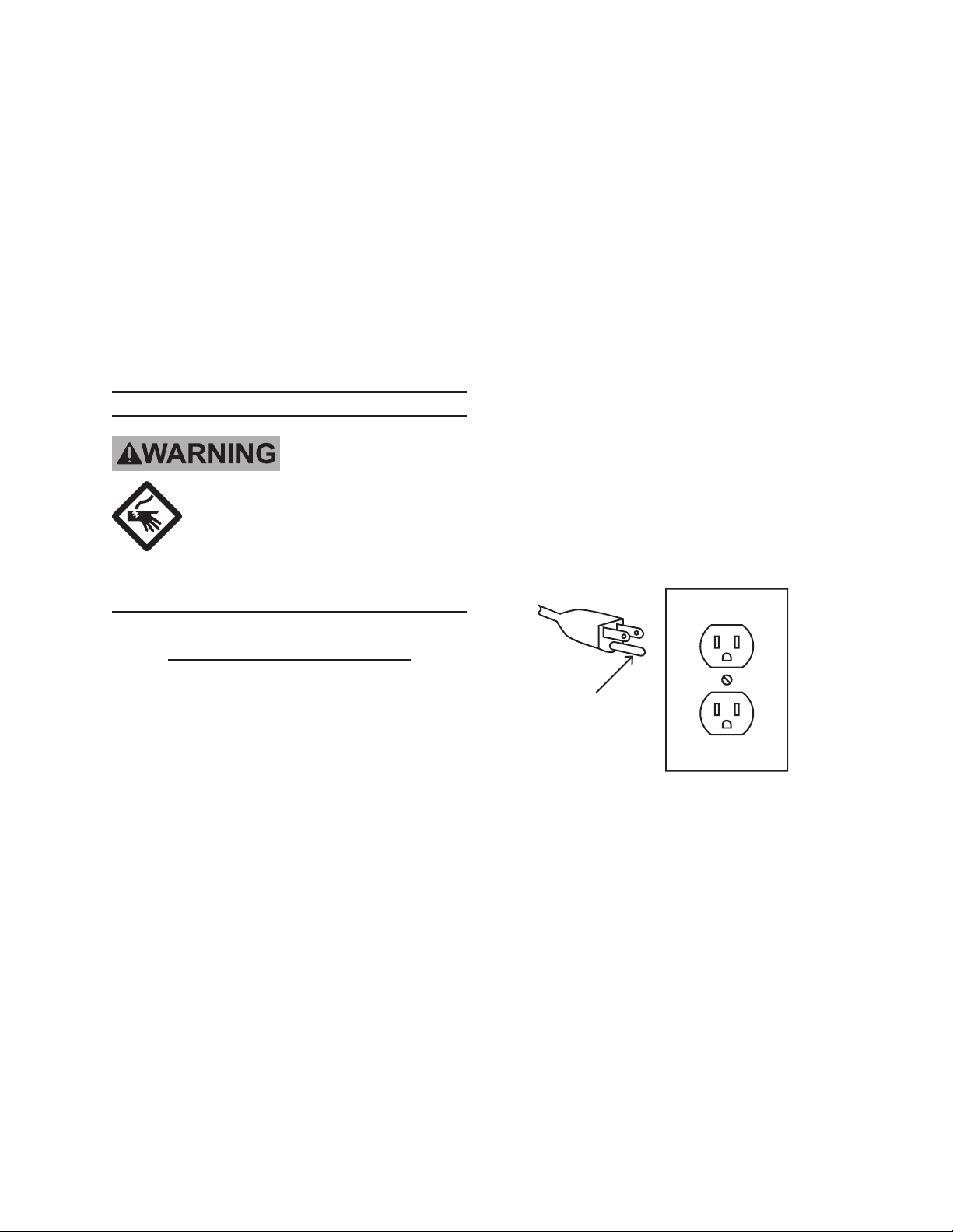
Grounding
Pin
125 V~ 3-Prong Plug and Outlet
(for up to 125 V~ and up to 15 A)
This tool is intended for use on a cir-7.
cuit that has an outlet that looks like
the one illustrated above in 125 V~
3-Prong Plug and Outlet. The tool
has a grounding plug that looks like
the plug illustrated above in 125 V~
3-Prong Plug and Outlet.
The outlet must be properly installed 8.
and grounded in accordance with all
codes and ordinances.
SKU 1624 For technical questions, please call 1-800-444-3353. Page 4
Page 5

Do not use an adapter to connect this 9.
tool to a different outlet.
Cutoff Saw Safety Warnings
CHECK WHEEL PRIOR TO USE. 1.
Check for any cracks or other aws in
the wheel that would indicate structural damage. If any are detected,
discard immediately. Never start the
saw if you or any one else is in line
with the wheel.
SECURE WORK. Use the Vise 2.
Clamp Assembly at all times to secure your work.
standards agency. Unapproved
safety equipment may not provide
adequate protection. Eye protection
must be ANSI-approved and breathing protection must be NIOSH-ap-
proved for the specic hazards in the
work area.
Industrial applications must follow 10.
OSHA guidelines.
Maintain labels and nameplates on 11.
the tool. These carry important safety
information. If unreadable or missing, contact Harbor Freight Tools for a
replacement.
DO NOT REMOVE THE SAFETY 3.
CHAIN.
FOR METAL CUTTING USE ONLY. 4.
Do not use to cut wood, masonry,
magnesium, plastic, or any other nonmetallic material. Never mount any
wheels not designed for metal cutting
operations.
ALLOW STOCK TO COOL AFTER 5.
CUTTING. Do not use uids to cool
materials faster. Allow to cool at a
normal rate.
DO NOT OPERATE WITH ANY 6.
GUARD DISABLED, DAMAGED,
OR REMOVED. Moving guards
must move freely and close instantly.
The use of accessories or attach-7.
ments not recommended by the
manufacturer may result in a risk of
injury to persons.
When servicing use only identical 8.
replacement parts.
Only use safety equipment that has 9.
been approved by an appropriate
Avoid unintentional starting. Prepare 12.
to begin work before turning on the
tool.
People with pacemakers should 13.
consult their physician(s) before use.
Electromagnetic elds in close proximity to heart pacemaker could cause
pacemaker interference or pacemaker failure.
WARNING: Some dust created by 14.
power sanding, sawing, grinding, drilling, and other construction activities,
contains chemicals known [to the
State of California] to cause cancer,
birth defects or other reproductive
harm. Some examples of these
chemicals are:
• Lead from lead-based paints
• Crystalline silica from bricks and ce-
ment or other masonry products
• Arsenic and chromium from chemically treated lumber
Your risk from these exposures varies, depending on how often you do
this type of work. To reduce your
exposure to these chemicals: work in
a well ventilated area, and work with
approved safety equipment, such as
SKU 1624 For technical questions, please call 1-800-444-3353. Page 5
Page 6

those dust masks that are specially
designed to lter out microscopic
particles. (California Health & Safety
Code § 25249.5, et seq.)
physical symptoms related to vibration (such as tingling, numbness, and
white or blue ngers), seek medical
advice as soon as possible.
WARNING: Handling the cord on 15.
this product will expose you to lead,
a chemical known to the State of
California to cause cancer, and birth
defects or other reproductive harm.
Wash hands after handling. (California Health & Safety Code § 25249.5,
et seq.)
The warnings, precautions, and in-16.
structions discussed in this instruction
manual cannot cover all possible conditions and situations that may occur.
It must be understood by the operator
that common sense and caution are
factors which cannot be built into this
product, but must be supplied by the
operator.
Vibration Safety
This tool vibrates during use. Repeated or long-term exposure to
vibration may cause temporary or
permanent physical injury, particularly
to the hands, arms and shoulders. To
reduce the risk of vibration-related
injury:
Do not smoke during use. Nico-2.
tine reduces the blood supply to the
hands and ngers, increasing the risk
of vibration-related injury.
Wear suitable gloves to reduce the 3.
vibration effects on the user.
Use tools with the lowest vibration 4.
when there is a choice between different processes.
Include vibration-free periods each 5.
day of work.
Grip tool as lightly as possible (while 6.
still keeping safe control of it). Let
the tool do the work.
To reduce vibration, maintain the tool 7.
as explained in this manual. If any
abnormal vibration occurs, stop use
immediately.
SAVE THESE
INSTRUCTIONS.
Anyone using vibrating tools regu-1.
larly or for an extended period should
rst be examined by a doctor and
then have regular medical checkups to ensure medical problems are
not being caused or worsened from
use. Pregnant women or people
who have impaired blood circulation
to the hand, past hand injuries, nervous system disorders, diabetes, or
Raynaud’s Disease should not use
this tool. If you feel any medical or
SKU 1624 For technical questions, please call 1-800-444-3353. Page 6
Page 7

SPECIFICATIONS
Electrical Input 120 V~ / 60 Hz / 3.5 HP
Motor No Load Speed 3800 RPM
Wheel: 14”, 1” arbor
Capacities: 3” x 8-1/2” (at); 4”
(pipe)
Remove the Wheel from the BUSH-5.
ING (#59).
Replace Wheel, and reassemble unit.6.
When tightening the BOLT, make sure 7.
that the BLADE LOCK is pressed down,
and the BOLT is tightened securely, but
not over tightened.
UNPACKING
When unpacking, make sure that the
item is intact and undamaged. If any parts
are missing or broken, please call Harbor
Freight Tools at 1-800-444-3353 as soon
as possible.
OPERATION
Removal & Installation of Wheel
Disconnect machine from power sup-1.
ply.
Push GUARD (#50) up and out of the 2.
way.
Blade Lock
(#47)
Vise Assembly Operation
Stock
Vise
Assembly
Figure 2 -- Positioning Stock
1. Your stock should always be centered
under the Wheel. Set the vise assembly as shown in Figure 2.
Guard
(#50)
Bolt (#68)
(one of two)
Figure 1 -- Blade Lock and Guard
3. Push in BLADE LOCK (#47), as
shown in Figure 1, and slowly turn
Wheel until it “clicks” into place. Do
not release the BLADE LOCK.
Remove the BOLT (#61), WASHER 4.
(#62), and FLANGE WASHER (#58).
SKU 1624 For technical questions, please call 1-800-444-3353. Page 7
Vise Stop
(#69)
Figure 3 -- Operating the Vise Assembly
2. Loosen the two BOLTS (#68) as
shown in Figure 3 and move the
Vise Face
(#67)
Release
Handle
(#89)
Vise Handle
(#92)
Page 8

VISE STOP (#69) to the desired position. Tighten the BOLTS.
Raise the VISE LEAD SCREW RE-3.
LEASE HANDLE (#89) and slide
the VISE FACE (#67) forward until it
contacts the stock.
Lower the RELEASE HANDLE 4.
so that it rests against the LEAD
SCREW (#81). Turn the VISE HANDLE (#92) to tightly clamp the stock.
Miter Cuts
Position stock as detailed in Step 1 of 1.
Vise Assembly Operation, above.
Depth of Cut Adjustment
Set Bolt
Adjustment
Depth
Bolt
Position the VISE STOP (#69) as 2.
detailed in Step 2. Before tightening
the BOLTS (#68), position the VISE
STOP to the desired angle (from –30°
to +45°).
Advance the VISE FACE (#67) as de-3.
tailed in Steps 3 & 4. The FACE will
adjust to the angle of your stock.
Figure 4 -- Adjusting Depth of Cut
1. Loosen the Set Nut on the Depth Adjustment Bolt as shown in Figure 4.
Raise or lower the Depth Adjustment 2.
Bolt as necessary to obtain the desired depth of cut.
SKU 1624 For technical questions, please call 1-800-444-3353. Page 8
Page 9

MAINTENANCE
Changing the Brushes
Wheel Alignment
If the Wheel gets out of alignment
and begins to contact the BASE (#74), the
following procedures must be observed.
Secure the Wheel in the locked down 1.
position.
Tilt the unit on its side.2.
Slightly loosen the four BOLTS (#38) 3.
that hold the two PIVOT BLOCKS
(#63) in place.
Slide the unit so that the Wheel is 4.
centered in the slot of the BASE.
Make sure that the Wheel is at a 5.
90° angle to the BASE using a Try-
Square.
Tighten the four BOLTS.6.
The BRUSHES (#3) must be replaced when less than 3/8” remains. Both
BRUSHES must be replaced at the same
time.
Brush
Cap
(#1)
Brush
(#3)
Brush
Holder
(#4)
Figure 5 -- Replacing Brush
1. Remove the BRUSH CAPS (#1) as
shown in Figure 5.
Remove the old BRUSHES from the 2.
BRUSH HOLDERS (#4) and replace
with new BRUSHES.
Replace the BRUSH CAPS.3.
Cleaning
Use a chip brush between every 1.
operation to remove all metal lings
from the base and unit. Never use
hands to brush unit!
Use compressed air (at 10 PSI) to 2.
keep the main air vents free from dirt
and grease.
SKU 1624 For technical questions, please call 1-800-444-3353. Page 9
Page 10

PLEASE READ THE FOLLOWING CAREFULLY
THE MANUFACTURER AND/OR DISTRIBUTOR HAS PROVIDED THE PARTS LIST AND ASSEMBLY
DIAGRAM IN THIS MANUAL AS A REFERENCE TOOL ONLY. NEITHER THE MANUFACTURER OR
DISTRIBUTOR MAKES ANY REPRESENTATION OR WARRANTY OF ANY KIND TO THE BUYER THAT
HE OR SHE IS QUALIFIED TO MAKE ANY REPAIRS TO THE PRODUCT, OR THAT HE OR SHE IS
QUALIFIED TO REPLACE ANY PARTS OF THE PRODUCT. IN FACT, THE MANUFACTURER AND/
OR DISTRIBUTOR EXPRESSLY STATES THAT ALL REPAIRS AND PARTS REPLACEMENTS SHOULD
BE UNDERTAKEN BY CERTIFIED AND LICENSED TECHNICIANS, AND NOT BY THE BUYER. THE
BUYER ASSUMES ALL RISK AND LIABILITY ARISING OUT OF HIS OR HER REPAIRS TO THE
ORIGINAL PRODUCT OR REPLACEMENT PARTS THERETO, OR ARISING OUT OF HIS OR HER
INSTALLATION OF REPLACEMENT PARTS THERETO.
PARTS LIST
Part Code Description
1 8bd315017 Brush Cap
2 gb34521 O-Ring
3 5bd573017 Brush
4 8bd112049 Brush Holder
5 gb90744 Screw
6 8bd313016 Brush Cover
7 8bd156075 Washer
8 gb77 Set Screw
9 8bd322005 Nylon Ball
10 8bd313015 End Plate
11 6bd720128 Field Case
12 8bd680456 Nameplate
13 8bdd557023 Terminal
14 Gb818 Screw
15 Gb90743 Screw
16 5bd670164 Field
17 8bd016052 Fan Bafe
18 gb279 Ball Bearing
19 6bd190096 Armature
20 5bd435038 Fan
21 gb279 Ball Bearing
22 8bd282094 Spring
23 8bd551017 Terminal
24 gb90744 Screw
25 gb90744 Screw
26 8bd306063 Switch Handle Cover
27 gb845 Screw
28 8bd490011 Switch
29 8bd306062 Switch Handle
30 gb90744 Screw
31 Chain
32 8bd921004 Screw
33 8bd218037 Spacer
34 gb6175 Nut
35 Attachment Plug
36 8bd777027 Cord Protector
37 6bd641043 Cord
38 gb907414 Bolt
39 8bd253052 Spade Handle
40 gb93 Washer
41 8bd Main Spring
42 8bd010017 Gear Case
43 gb290 Needle Bearing
44 8bd240154 Gear
45 8bd206080 Spindle
46 8bd003009 Gear Case Cover
Part Code Description
47 8bd934026 Blade Lock
48 gb90743 Screw
49 8bd472005 Lock Hook
50 5bd300017 Guard
51 8bd300041 Bumper
52 gb41 Nut
53 8bd300042 Spark Deector
54 gb95 Washer
55 8bd921005 Screw
56 8bd218035 Spacer
57 gb95 Washer
58 8bd128107 Flange Washers
59 8bd218036 Bushing
60 N/A N/A
61 gb5786 Bolt
62 8bd156072 Washer
63 8bd730006 Pivot Block
64 gb90743 Screw
65 8bd128110d Vise Stop Plate
66 gb41 Nut
67 8bd128109 Vise Face
68 gb907414 Bolt
69 8bd128108 Vise Stop
70 8bd150033 Steel Foot
71 gb90744 Screw
72 8bd016053 Shield
73 gb894 Retaining Ring
74 8bd150034 Base
75 gb95 Washer
76 8bd128111 Cord Clamp
77 gb95 Washer
78 gb90744 Screw
79 8bd150032 Rubber Foot
80 8bd156073 Saddle
81 8bd235013 Lead Screw
82 8bd253051 Handle Knob
83 8bd253050 Handle Arm
84 gb96 Washer
85 gb90743 Screw
86 gb879 Roll Pin
87 8bd235014 Vise Mount
88 8bd934024 Pin
89 8bd941012 Release Handle
90 gb95 Washer
91 8bd934025 Clevis Pin
92 Vise Handle
SKU 1624 For technical questions, please call 1-800-444-3353. Page 10
Page 11

ASSEMBLY DIAGRAM
Record Product’s Serial Number Here:
Note: If product has no serial number, record month and year of purchase instead.
Note: Some parts are listed and shown for illustration purposes only, and are not avail-
able individually as replacement parts.
SKU 1624 For technical questions, please call 1-800-444-3353. Page 11
Page 12

LIMITED 1 YEAR / 90 DAY WARRANTY
Harbor Freight Tools Co. makes every effort to assure that its products meet high
quality and durability standards, and warrants to the original purchaser that for a period
of ninety days from date of purchase that the engine/motor, the belts (if so equipped),
and the blades (if so equipped) are free of defects in materials and workmanship. Harbor Freight Tools also warrants to the original purchaser, for a period of one year from
date of purchase, that all other parts and components of the product are free from
defects in materials and workmanship (90 days if used by a professional contractor or
if used as rental equipment). This warranty does not apply to damage due directly or
indirectly, to misuse, abuse, negligence or accidents, repairs or alterations outside our
facilities, normal wear and tear, or to lack of maintenance. We shall in no event be liable
for death, injuries to persons or property, or for incidental, contingent, special or consequential damages arising from the use of our product. Some states do not allow the
exclusion or limitation of incidental or consequential damages, so the above limitation
of exclusion may not apply to you. THIS WARRANTY IS EXPRESSLY IN LIEU OF ALL
OTHER WARRANTIES, EXPRESS OR IMPLIED, INCLUDING THE WARRANTIES OF
MERCHANTABILITY AND FITNESS.
To take advantage of this warranty, the product or part must be returned to us with
transportation charges prepaid. Proof of purchase date and an explanation of the complaint must accompany the merchandise. If our inspection veries the defect, we will either repair or replace the product at our election or we may elect to refund the purchase
price if we cannot readily and quickly provide you with a replacement. We will return repaired products at our expense, but if we determine there is no defect, or that the defect
resulted from causes not within the scope of our warranty, then you must bear the cost
of returning the product.
This warranty gives you specic legal rights and you may also have other rights
which vary from state to state.
3491 Mission Oaks Blvd. • PO Box 6009 • Camarillo, CA 93011 • (800) 444-3353
SKU 1624 For technical questions, please call 1-800-444-3353. Page 12
 Loading...