

Harbor Breeze LP8210LAZ User Manual
1
Español p. 22
ITEM #0232645
MODEL #LP8210LAZ
ROCK HALL CEILING FAN
Harbor Breeze® is a registered trademark
of LF, LLC. All Rights Reserved.
Questions, problems, missing parts? Before returning to your retailer, call our customer
service department at 1-888-567-2055, 8 a.m. - 5 p.m., EST, Monday - Friday.
ATTACH YOUR RECEIPT HERE
Serial Number
Purchase Date
Lowes.com/harborbreeze

2
Lowes.com/harborbreeze
TABLE OF CONTENTS
Package Contents .........................................................................................................................
Hardware Contents .......................................................................................................................
Safety Information .........................................................................................................................
Preparation ...................................................................................................................................
Assembly Instructions ...................................................................................................................
Wiring Instructions ........................................................................................................................
Final Assembly Instructions ..........................................................................................................
Operating Instruction ....................................................................................................................
Blade Balancing Instructions ........................................................................................................
Care and Maintenance .................................................................................................................
Troubleshooting ............................................................................................................................
Warranty .......................................................................................................................................
Replacement Parts List ................................................................................................................
3
4
4
5
6
10
11
12
17
18
18
20
21
3
PART DESCRIPTION QUANTITY
J
K
F
G
H
L
M
I
B
C
D
E
A
N
Lowes.com/harborbreeze
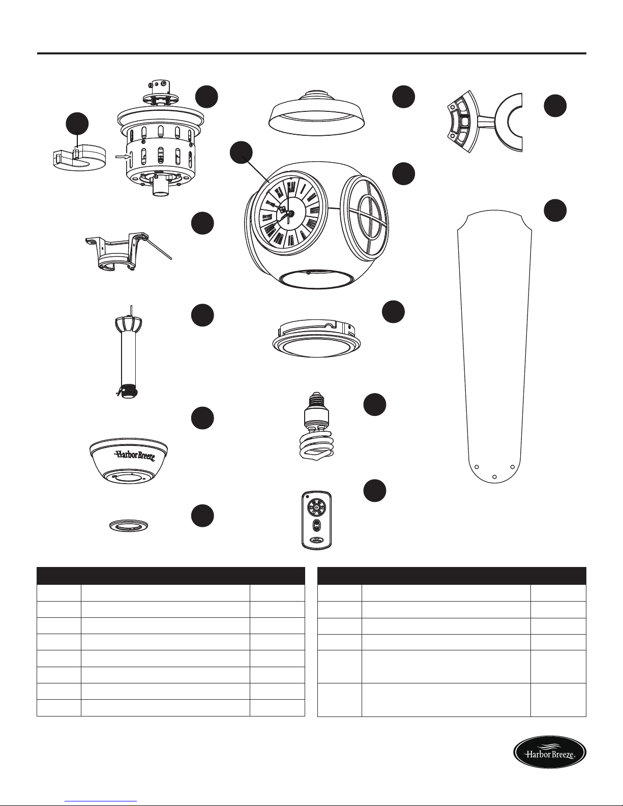
PACKAGE CONTENTS
PART DESCRIPTION QUANTITY
I
J
K
L
M
N
Bulb
Remote
Blade Arm
Blade
Clock Assembly (preassembled
to Housing Assembly (G))
Receiver Unit (preassembled
to
Motor Assembly
(A))
A
B
C
D
E
F
G
H
Motor Assembly
Hanger Bracket
Downrod
Ceiling Canopy
Canopy Screw Cover
Motor Coupling Cover
Housing Assembly
Glass
1
1
1
1
1
1
1
1
1
1
5
5
2
1
4
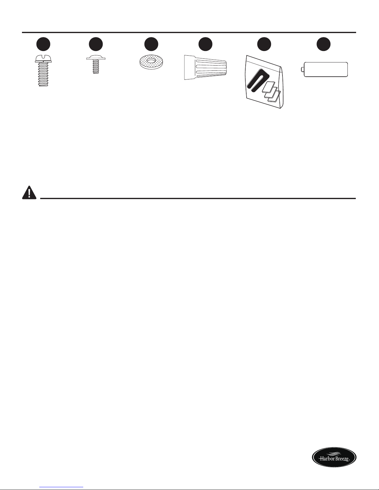
HARDWARE CONTENTS (shown actual size)
EE
Balance
Kit
(not shown
to size)
Qty. 1
Wire
Connectors
Qty. 4
DD
Screws
Qty. 11
AA
SAFETY INFORMATION
Please read and understand this entire manual before attempting to assemble, operate or install
the product.
• Before you begin installing the fan, disconnect the power by removing fuses or turning off circuit
breakers.
• Make sure all electrical connections comply with local codes, ordinances, or the National
Electrical code. Hire a qualified electrician or consult a do-it-yourself wiring handbook if you are
unfamiliar with installing electrical wiring.
• Make sure the installation site you choose allows a minimum clearance of 7 ft. from the blades
to the floor and at least 30 in. from the ends of the blades to any obstruction.
• If you are mounting the fan to a ceiling outlet box, use a METAL octagonal outlet box.
Secure the box directly to the building structure. The outlet box and its support must be able to
support the moving weight of the fan (at least 35 lbs.). Do NOT use a plastic outlet box.
• After you install the fan, make sure all connections are secure to prevent the fan from falling.
• For supply connections, if the conductor of a fan is identified as a grounded conductor, then it
should be connected to a grounded conductor power supply. If the conductor of a fan is identified
as an ungrounded conductor, then it should be connected to an ungrounded conductor power
supply. If the conductor of a fan is identified for equipment grounding, then it should be connected
to an equipment-grounding conductor.
• This device complies with Part 15 of the FCC Rules. Operation is subject to the following two
conditions: (1) This device may not cause harmful interference, and (2) this device must accept
any interference received, including interference that may cause undesired operation.
If the intentional radiator can be classified as a Class B digital device or a PC peripheral, then shall
include the following or equivalent:
Note: This equipment has been tested and found to comply with the limits for Class B digital
device, pursuant to part 15 of the FCC Rules. These limits are designed to provide reasonable
protection against harmful interference in a residential installation. This equipment generates, uses
Fiber
Washers
Qty. 16
CC
BB
Washer-Head
Screws
Qty. 16
Lowes.com/harborbreeze
FF
Battery
(not shown
to size)
Qty. 2
5
SAFETY INFORMATION
•The net weight of this fan is: 18.63 lbs.
Before beginning assembly of product, make sure all parts are present. Compare parts with
package contents list and hardware contents list. If any part is missing or damaged, do not
attempt to assemble the product.
Estimated Assembly Time: 60 minutes
Tools Required for Assembly (not included): Phillips screwdriver, 1/4 in. flathead screwdriver,
wire stripper and step ladder.
Helpful Tools (not included): AC tester light, do-it-yourself wiring handbook and wire cutters.
PREPARATION
and can radiate radio frequency energy and, if not installed and used in accordance with the
instructions, may cause harmful interference to radio or television reception, which can be
determined by turning the equipment off and on, the user is encouraged to try to correct the
interference by one or more of the following measures:
- Reorient or relocate the receiving antenna.
- Increase the separation between the equipment and the receiver.
- Connect the equipment into an outlet on a circuit different from that to which the receiver is
connected.
Consult the dealer or an experienced radio/TV technician for help.
Note: For a Class A digital device, statements of 15. 105(a) must be included when appropriate for
the device in question.
Lowes.com/harborbreeze
WARNING
• Do not install or use fan if any part is damaged or missing.
• To reduce the risk of fire, electrical shock, or personal injury, wire connectors provided with this
fan are designed to accept only one 12-gauge house wire and two lead wires from the fan. If
your house wire is larger than 12-gauge or there is more than one house wire to connect to the
two fan lead wires, consult an electrician for the proper size wire connectors to use. Before
cutting, drilling or hammering, verify their location. If needed, contact your electrician, plumber
or service person.
• To reduce the risk of fire, electric shock, or personal injury, do not bend the blade arms when
installing them, balancing the blades, or cleaning the fan. Do not insert foreign objects between
the rotating fan blades. Mount to outlet box marked “ACCEPTABLE FOR FAN SUPPORT” and
use mounting screws provided with the outlet box. Most outlet boxes commonly used for the
support of lighting fixtures are not acceptable for fan support and may need to be replaced.
Consult a qualified electrician if in doubt.
• This fan is to be used in dry locations only.
• Read all instructions and safety information before installing the new fan. Review accompanying
assembly diagrams.
CAUTION
6
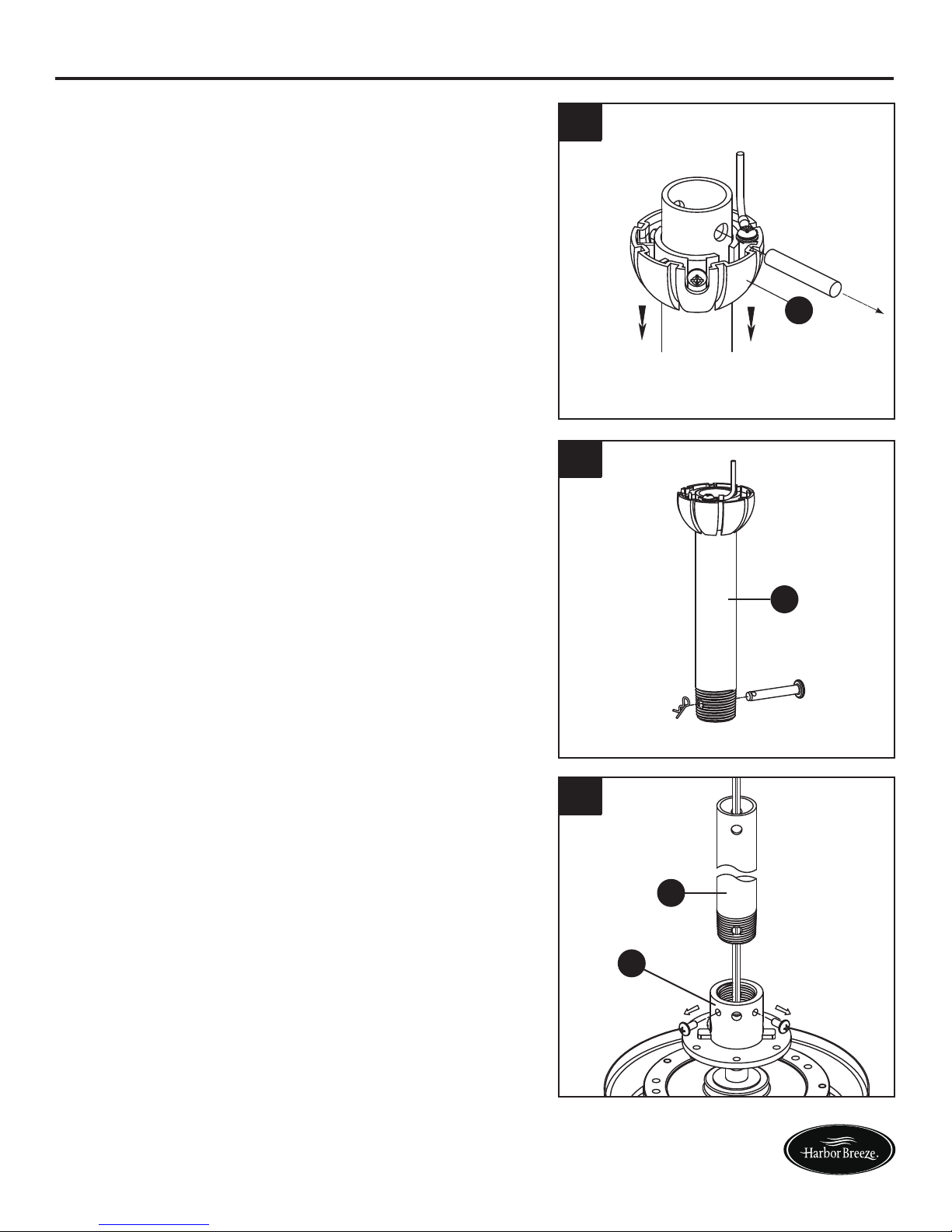
ASSEMBLY INSTRUCTIONS
1. Remove the hanger ball portion from the
downrod (C) by loosening the preassembled
set screw in the hanger ball until the ball falls
freely down the downrod (C). Remove the
preassembled pin from the downrod (C), then
remove the hanger ball. Retain the pin and
hanger ball for later.
2. Remove the preassembled hairpin clip and
clevis pin from the bottom of downrod (C).
Retain the pin and clip for later.
3. Loosen the two preassembled set screws in
the downrod support of the motor assembly
(A). Route the black and white wires through
the downrod (C).
C
A
C
C
Lowes.com/harborbreeze
1
2
3
7
K
A
AA
6
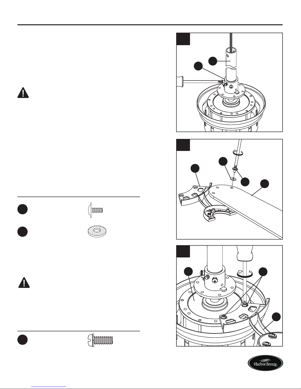
ASSEMBLY INSTRUCTIONS
4. Thread the downrod (C) into downrod support
of the motor assembly (A). Align the holes in
the downrod support of the motor assembly (A)
with the holes in the downrod (C) and install the
previously removed clevis pin. Secure clevis
pin with previously removed hairpin clip.
Tighten the two set screws in the downrod
support of the motor assembly (A).
Hardware Used
BB
Washer-Head
Screws
CC
Fiber
Washers
x 15
x 15
5. Position the blades (L) over the blade arms (K)
with threaded posts showing. Make sure the
bottom edge of the blades (L) are fully seated
against the blade arms (K). Install and tighten
the washer-head screws (BB) with fiber
washers (CC) to secure the blades (L) to the
blade arms (K).
Lowes.com/harborbreeze
WARNING
It is critical the clevis pin in the downrod support
is properly installed and the set screws are
securely tightened. Failure to do so could result
in the fan falling.
NOTE: Periodically check blade arms hardware
and resecure if necessary.
AA
Hardware Used
x 10
Screws
6. Attach blade arms (K) to the hub of motor
assembly (A) using screws (AA).
WARNING
To reduce the risk of personal injury, do not
bend the blade holders when installing,
balancing the blades or cleaning the fan. Do not
insert foreign objects in between the rotating
blades.
4
C
A
5
K
L
CC
BB
8
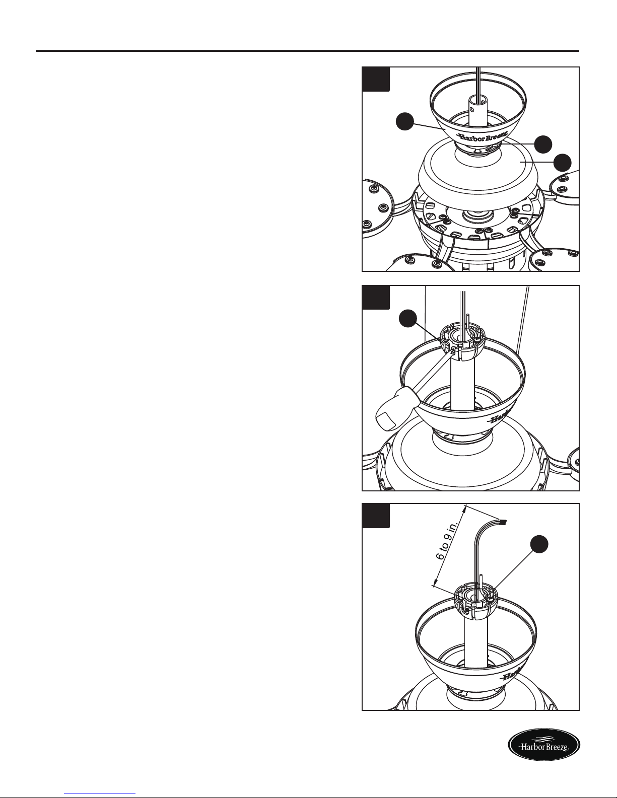
ASSEMBLY INSTRUCTIONS
7. Route wires through motor coupling cover
(F), canopy screw cover (E) and ceiling
canopy (D).
8. Reinstall the hanger ball on the downrod (C)
by routing the two 54 in. wires from the motor
assembly (A) through the hanger ball. Position
the pin removed in step 1 through the two
holes in the downrod (C) and align the hanger
ball so the pin is captured in the groove in the
top of the hanger ball. Pull the hanger ball up
tight against the pin. Securely tighten the
preassembled set screw in the hanger ball.
9. Cut off excess lead wire approximately 6 to 9
in. above top of the top of the downrod (C).
Strip insulation off 1/2 in. from the end of each
lead wire.
C
C
Lowes.com/harborbreeze
A loose set screw could result in a wobbly fan.
CAUTION
8
9
1
D
E
F
7
9
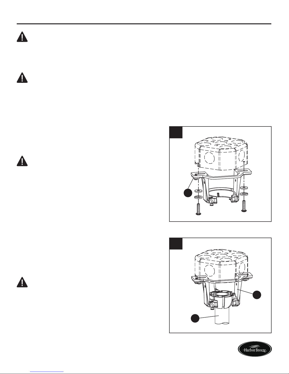
ASSEMBLY INSTRUCTIONS
B
10
10. Securely attach the hanger bracket (B) to the
outlet box (not included) using the outlet box
screws and washers supplied with the outlet
box.
B
C
11
11. Carefully lift the assembly and seat hanger
ball of the downrod (C) on the hanger bracket
(B). Be sure the groove in the ball is lined up
with tab on the hanger bracket (B).
Lowes.com/harborbreeze
NOTE: If you are not sure if the outlet box is grounded, contact a licensed electrician for advice, as
it must be grounded for safe operation.
WARNING
To avoid possible electrical shock, be sure electricity is turned off at the main fuse box before
hanging.
WARNING
The fan must hang with at least 7 ft. of clearance from the floor to blades.
WARNING
The outlet box must be securely anchored.
Hanger bracket must seat firmly against outlet
box. If the outlet box is recessed, remove
wallboard until bracket contacts box. If bracket
and/or outlet box are not securely attached, the
fan could wobble or fall.
WARNING
Failure to seat tab in groove could cause damage
to electrical wires and possible shock or fire
hazard.
To avoid possible shock, do not pinch wires
between the hanger ball assembly and the
hanger bracket.
10
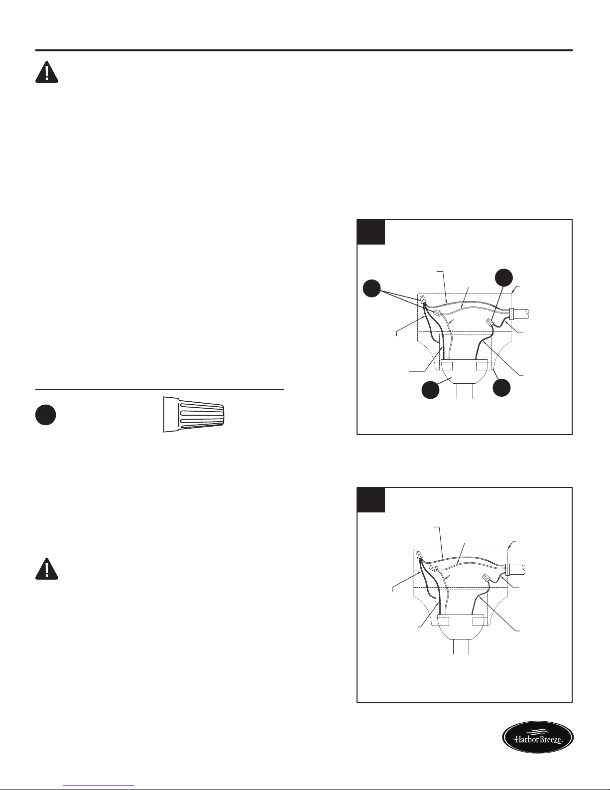
WIRING INSTRUCTIONS
NOTE: If you are not sure if the outlet box is grounded, contact a licensed electrician for advice, as
it must be grounded for safe operation.
1. Connect the green grounding lead from the
downrod (C) and the green grounding lead from
the hanger bracket (B) to the supply grounding
conductor (this may be a bare wire or wire with
green colored insulation). Securely connect
wires with wire connector (DD). Securely
connect the white fan motor wire to the white
supply (neutral) wire using wire connector (DD).
Securely connect the black fan motor wire to
the black supply wire using wire connector (DD).
Hardware Used
DD
x 3
Wire
Connectors
1
DD
DD
C
B
Green Wire
from Supply
(Ground)
White Wire
from Supply
White Wire
from Fan
Green Wire
from Hanger
Bracket (Ground)
Green Wire
from Hanger
Ball (Ground)
Listed
Outlet Box
Household
Supply
Black Wire
from Supply
Black Wire
from Fan
2. After connections have been made, turn leads
upward and carefully push leads into the outlet
box, with the white and green leads to one side
of the box and the black leads toward the
other side.
Green Wire
from Supply
(Ground)
White Wire
from Supply
White Wire
from Fan
Green Wire
from Hanger
Bracket (Ground)
Green Wire
from Hanger
Ball (Ground)
Listed
Outlet Box
Household
Supply
Black Wire
from Supply
Black Wire
from Fan
2
Lowes.com/harborbreeze
To avoid possible electrical shock, be sure electricity is turned off at the main fuse box before wiring.
WARNING
WARNING
Check to see all connections are tight, including
ground, and no bare wire is visible at the wire
connectors except for the ground wire. Do not
operate fan until the blades are in place. Noise
and motor damage could result.

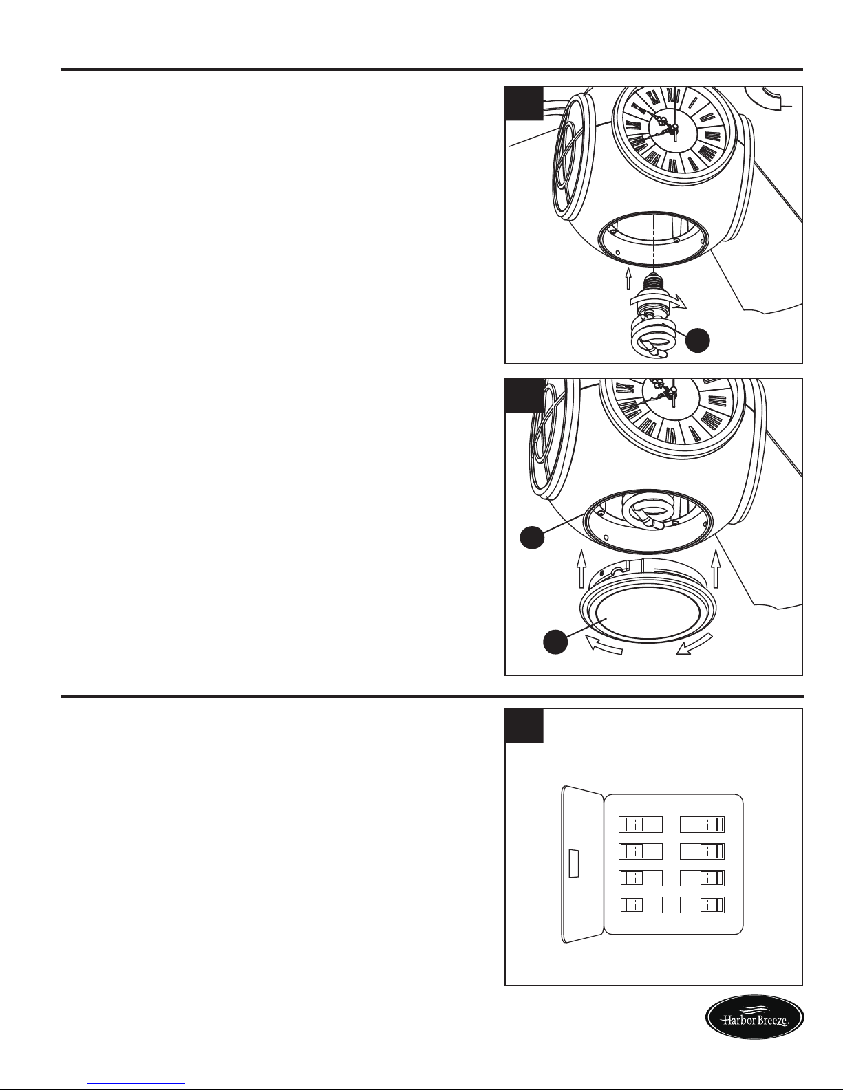
11
1. Remove one of the two preassembled
shoulder screws in the hanger bracket (B).
Loosen the second shoulder screw without
fully removing it. Rotate ceiling canopy (D) so
second shoulder screw moves into the small
opening of the keyslot. Tighten shoulder
screw. Re-install the previously removed
shoulder screw to fully assemble ceiling
canopy (D) to hanger bracket (B).
3. Remove one of the four preassembled screws
inside the adaptor plate at the bottom of the
motor assembly (A). Slightly loosen the
remaining three screws. Assemble the
housing assembly (G) to the adaptor plate of
the motor assembly (A) using the three
keyslots in the housing assembly (G). Replace
the fourth screw and securely tighten all four
screws.
FINAL ASSEMBLY INSTRUCTIONS
2. Securely attach and tighten the canopy
screw cover (E) over the shoulder screws in
the hanger bracket (B), utilizing the keyslot
twist-lock feature.
Lowes.com/harborbreeze
WARNING
To avoid possible fire or shock, make sure the
electrical wires are completely inside the canopy
housing and not pinched between the housing
and the ceiling.
1
D
2
E
A
G
3
12
OPERATING INSTRUCTIONS
1. Restore electrical power to the outlet box by
turning the electricity on at the main fuse box.
1
ON
ON
ON
ON
ON
ON
ON
ON
FINAL ASSEMBLY INSTRUCTIONS
4. Install bulb (I).
5. Securely attach glass (H) by twisting clockwise
onto the housing assembly (G).
5
H
G
I
4
Lowes.com/harborbreeze
Do no overtighten or force connection.
CAUTION
13
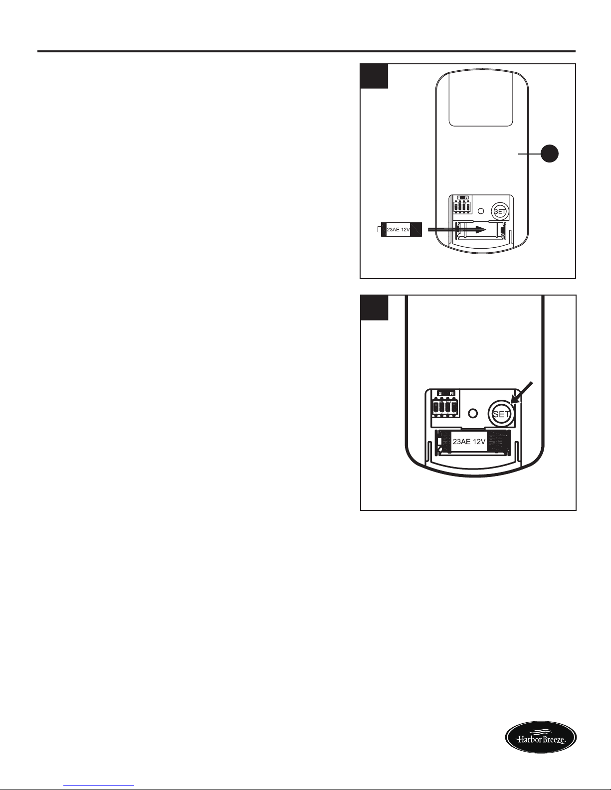
OPERATING INSTRUCTIONS
2
J
2. To make fan operational, install 12-volt battery
(included in remote control package) into the
remote (J).
3. Follow the below steps to set the remote (J):
a) With the fan’s power off, arrange code
switches to desired code setting.
b) After installing the unit and restoring
power to the fan, press and hold the “SET”
button 1~5 seconds. You must press the
“SET” button within 60 seconds of restoring
power to the fan.
c) The fan will start to run and begin the
control setting process. The fan will run in
both directions for a total of approximately 5
minutes.
d) When the fan stops after approximately 5
minutes the control and speed setting
process is complete and the fan is ready for use.
3
Lowes.com/harborbreeze
If you are not expecting to use the remote for a
long period of time, remove the battery to
prevent damage to the remote. Be sure to store
the remote away from excess heat or humidity.
CAUTION
 Loading...