

Harbor Breeze L2B1 Installation Manual
Harbor Breeze® is a registered trademark
of LF, LLC. All Rights Reserved.
ITEM #0102524
MODEL #L2B1
EDENTON CEILING FAN
1
Español p. 20
®
Questions, problems, missing parts?
Before returning to your retailer, call our customer
service department at 1-800-643-0067, 8 a.m. - 6 p.m., EST, Monday - Thursday, 8 a.m. - 5
p.m., EST, Friday.
Lowes.com/harborbreeze
ATTACH YOUR RECEIPT HERE
Serial Number
Purchase Date
EB14425

2
Preparation ...........................................................................................................................
Initial Instructions ..................................................................................................................
Standard/Angle-Mounting Instructions ..................................................................................
Flushmount Instructions ........................................................................................................
Wiring Instructions ..............................................................................................................
Final Instructions ..................................................................................................................
Operating Instructions .............................................................................................................
Care and Maintenance .........................................................................................................
Safety Information ................................................................................................................
4
Package Contents ................................................................................................................
Hardware Contents ..............................................................................................................
3
4
5
6
7
9
10
11
14
15
Troubleshooting ...................................................................................................................
Limited Lifetime Warranty ....................................................................................................
15
18
Replacement Parts List ........................................................................................................
19
Lowes.com/harborbreeze
TABLE OF CONTENTS
PACKAGE CONTENTS
3
Lowes.com/harborbreeze
A
B
C
D
K
N
S
J
Q
R
M
F
L
H
E
I
G
P
O
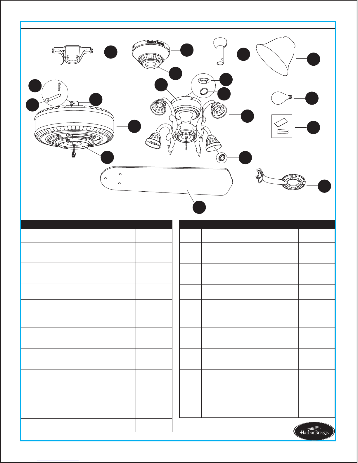
A Mounting Bracket 1
B Canopy 1
C
Canopy Cover
(preassembled on Canopy (B))
1
D Downrod Assembly 1
E
Coupling
(preassembled on Motor
Housing (H))
1
F Blade Iron 5
G Blade 5
H Motor Housing 1
I
Mounting Plate
(preassembled on Motor
Housing (H))
1
J Light Kit 1
PART DESCRIPTION QUANTIT
K Glass Bowl 4
L
Switch Housing
(preassembled to Light Kit (J))
1
M
Socket Ring
(preassembled to Light Kit (J))
4
N Bulb 4
O
Clevis Pin
(preassembled to Coupling (E))
1
P
Hairpin Clip
(preassembled to Clevis Pin(O))
1
Q
Hex Nut
(preassembled to Light Kit (J))
1
R
Spring Washer
(preassembled to Light kit (J))
1
S Balance Kit 1
PART DESCRIPTION QUANTIT
4
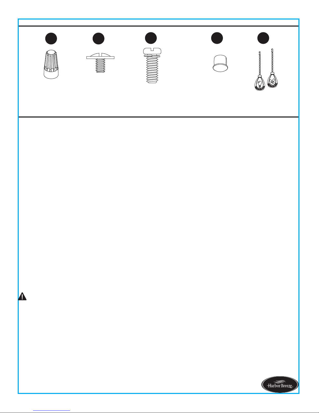
HARDWARE CONTENTS (not shown actual size)
SAFETY INFORMATION
Lowes.com/harborbreeze
READ AND SAVE THESE INSTRUCTIONS
All electrical connections must comply with local codes, ordinances or the National Electric Code (NEC).
Contact your municipal building department to inquire about your local codes, permits and/or inspections.
Turn off electricity at main fuse box (or circuit breaker box) before beginning installation by removing fuse or
by removing th fuse or by switching off circuit breaker.
Do not connect this fixture to an electrical system that does not provide a means for equipment grounding.
Never use a fixture in a two-wire system that is not grounded.
If you are not sure your lighting system has a grounding means, do not attempt to install this fixture. Contact
a qualified, licensed electrician for information regarding proper grounding methods as required by the local
electrical code in your area.
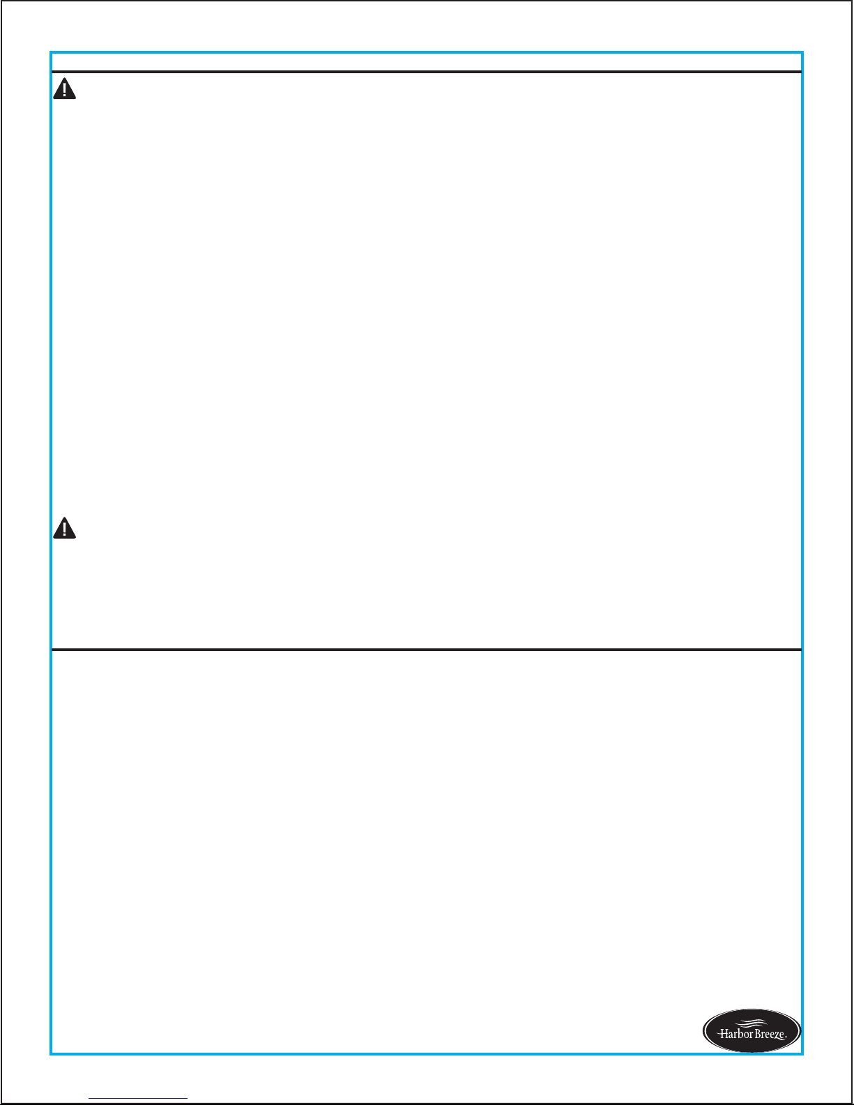
Make sure the installation site you choose allows a minimum clearance of 7 ft. from the blades to the floor
and at least 30 in. from the ends of the blades to any obstruction.
If a dimmer control switch is used with this fixture, obtain professional advice to determine the correct type
and electrical rating required.
The lighting fixture must be positioned so there is at least 1.64 ft. between the bulb and any illuminated
surface.
For supply connections, if the conductor of a fan is identified as a grounded conductor, then it should be
connected to a grounded conductor power supply. If the conductor of a fan is identified as an ungrounded
conductor, then it should be connected to an ungrounded conductor power supply. If the conductor of a fan
is identified for equipment grounding, then it should
be connected to an equipment-grounding conductor.
Connection of the bare or green fixture ground wire to the black or white house wires may allow metal parts
of the fixture to carry electrical currents. Under this condition anyone coming in contact with the fixture will
receive electrical shock, which could cause serious injury or death.
Installing a fixture into an electrical system without a proper grounding means could allow metal parts of the
fixture to carry electrical currents. If any of the fixture wires, wire connections or splices are broken, cut or
loose during the mounting or normal operation of the fixture, under such conditon, anyone coming in
contact with the fixture is subject to electrical shock, which could cause serious injury or death.
Be careful not to damage or cut the wire insulation (covering) during fixture installation. Do not permit wires
to have contact with any surface having a sharp edge. Doing so may damage or cut the wire insulation,
which could cause serious injury or death from electric shock.
Please read and understand this entire manual before attempting to assemble, operate or install the product.
DANGER
AA
BB
CC
DD EE
Wire Connector
Qty. 4
Blade Screw
Qty. 15 + 1 extra
Motor Screw
Qty. 10 (5 preassembled)
+ 1 extra
Fob
Qty. 2
Plastic Plug
Qty. 1
5
SAFETY INFORMATION
Lowes.com/harborbreeze
Risk of fire. Most dwellings built before 1985 have supply wire rated for 140°F. Consult a qualified
electrician before installation.
To reduce the risk of fire or electric shock, do not use this fan with any solid state fan speed device
or variable speed control.
To reduce the risk of personal injury, do not bend the blade brackets when installing the brackets,
balancing or cleaning the fan.
Do not insert foreign objects in between rotating fan blades.
Do not install or use the fan if any part is damaged or missing.
To reduce the risk of fire, electric shock or personal injury, mount to metal outlet box marked
'ACCEPTABLE FOR FAN SUPPORT OF 35 LBS OR LESS' and use mounting screws provided
with the outlet box and/or support directly from building structure. Most outlet boxes commonly
used for t
he support of luminaries are not acceptable for fan support and may need to be replaced.
Consult a qualified electrician if in doubt.
Before servicing or cleaning the unit, switch power off at the service panel and lock the service
disconnecting means to prevent power from being switched on accidentally. When the service
disconnecting means cannot be locked, securely fasten a prominent warning dev
ice, such as a tag,
to the service panel.
Do not use bulbs having a wattage greater than the maximum value stated on the fixture and in
this manual. Using a higher wattage bulb than specified will increase fixture temperature and
increase risk of fire.
Estimated Assembly Time: 45 minutes
CAUTION
PREPARATION
Before beginning assembly of product, make sure all parts are present. Compare parts with package
contents list and hardware contents list. If any part is missing or damaged, do not attempt to
assemble the product.
Tools Required for Assembly (not included): Philips Screwdriver, Step Ladder, Tape, Pliers and Wire
Cutters.
WARNING
7 ft. MIN.
30 in.
MIN.
2b
6
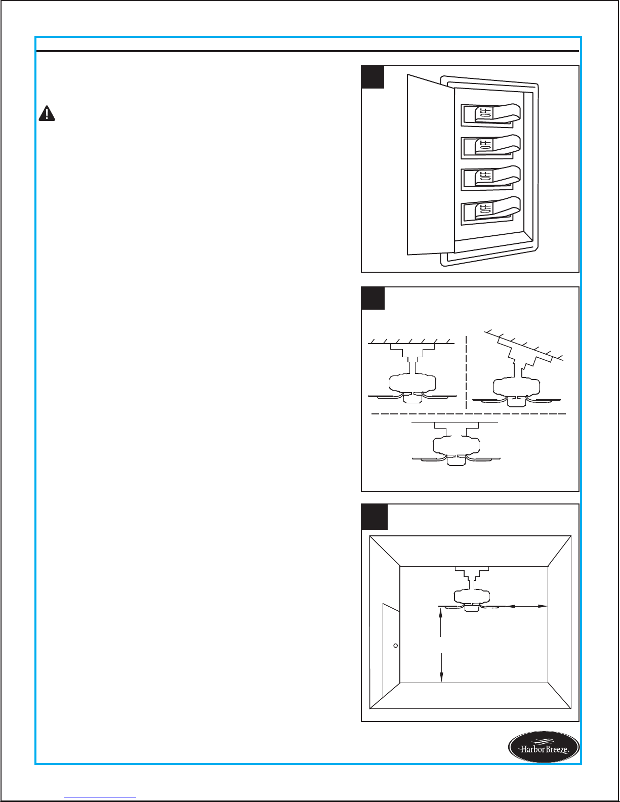
INITIAL INSTALLATION INSTRUCTIONS
1. Turn off circuit breakers and wall switch to the fan
supply line leads.
2a. Choose the desired mounting method:
2b. Make sure the installation site you choose allows a
minimum clearance of 7 ft. from the blades to the
floor and at least 30 in. from the ends of the blades
to any obstruction.
A. Standard Mounting: Standard mounting is best
suited for ceilings 8 ft. or higher. For taller ceilings you
may want to use a longer downrod (not included).
Lowes.com/harborbreeze
1
DANGER: Failure to disconnect power supply prior to
installation may result in serious injury or death.
B. Angle Mounting: Angle-style mounting is best suited
for angled or vaulted ceilings. A longer downrod is
sometimes necessary to ensure proper blade clearance.
If using the angle mount, make sure the ceiling angle is
not steeper than 20°.
C. Flush Mounting: Flushmount installation is used for
ceiling less than 8 ft. high.
2
A
B
C
 Loading...