

Harbor Breeze E-ER56ORB3LKLR Instructions Manual
ITEM #0219421
MONTE BELLO CEILING FAN
Harbor Breeze® is a registered trademark
of LF, LLC. All Rights Reserved.
MODEL #E-ER56ORB3LKLR
Español p. 23
Federal regulations require ceiling fans with light kits manufactured or imported after
January 1, 2009, to limit total wattage consumed by the light kit to 190W. Therefore,
this fan is equipped with a wattage limiting device.
ATTACH YOUR RECEIPT HERE
Serial Number
Questions, problems, missing parts? Before returning to your retailer, call or contact our
customer service department at 1-800-527-1292, 8:30 a.m. - 5:00 p.m., CST, Monday - Friday.
E192641
Purchase Date
1
TABLE OF CONTENTS
Safety Information ....................................................................................................................... 2 - 3
Product Overview ............................................................................................................................ 4
Package Contents ........................................................................................................................... 5
Hardware Contents ......................................................................................................................... 6
Preparation ...................................................................................................................................... 6
Initial Installation ........................................................................................................................ 7 - 8
Fan Mounting ............................................................................................................................ 8 - 11
Wiring Remote Control and Fan ............................................................................................ 11 - 13
Final Installation ...................................................................................................................... 13 - 16
Automated Learning Process/Activating Code ...................................................................... 16 - 17
Changing Reverse Switch Setting ................................................................................................ 17
Operation Instructions for Remote Control and Fan ............................................................. 18 - 19
Care and Maintenance .................................................................................................................. 19
Troubleshooting ............................................................................................................................. 20
Warranty ........................................................................................................................................ 21
Replacement Parts List ................................................................................................................. 22
SAFETY INFORMATION
READ AND SAVE THESE INSTRUCTIONS
Please read and understand this entire manual before attempting to assemble, install or operate the
product. If you have any questions regarding the product, please call customer service at
1-800-527-1292, 8:30 a.m.- 5:00 p.m., CST, Monday - Friday.
• Do not discard fan carton or foam inserts. Should this fan need to be returned to the factory for
repairs, it must be shipped in its original packaging to ensure proper protection against damage that
might exceed the initial cause for return.
• Make sure that all electrical connections comply with local codes, ordinances, the National Electrical
Code and ANSI/NFPA 70-1999. Hire a qualified electrician or consult a do-it-yourself wiring handbook,
available at Lowe's, if you are unfamiliar with installing electrical wiring.
• Make sure the installation site you choose allows a minimum clearance of 7 feet from the blades to
the floor and at least 30 in. from the end of the blades to any obstruction.
• After you install the fan, make sure that all connections are secure to prevent the fan from falling.
• The net weight of this fan including the light kit is: 21.27 lbs. (9.65 kg).
2
SAFETY INFORMATION
WARNINGS
To reduce the risk of fire, electrical shock, or personal injury, mount fan to outlet box
marked "ACCEPTABLE FOR FAN SUPPORT OF 35 LBS (15.9 KG) OR LESS" and use
mounting screws provided with the outlet box. Most outlet boxes commonly used for the
support of lighting fixtures are not acceptable for fan support and may need to be replaced.
Consult a qualified electrician if in doubt.
When mounting fan to a ceiling outlet box, use a METAL octagonal outlet box. Secure the outlet
box directly to the building structure. The outlet box and its support must be able to support the
moving weight of the fan (at least 35 lbs.). Do NOT use a plastic outlet box.
To avoid personal injury, the use of gloves may be necessary while handling fan parts with
sharp edges.
To reduce the risk of fire, electrical shock, or personal injury, wire connectors provided with this
fan are designed to accept only one 12-gauge house wire and two lead wires from the fan. If your
house wire is larger than 12-gauge or there is more than one house wire to connect to the two fan
lead wires, consult an electrician for the proper size wire connectors to use.
To reduce the risk of fire or electrical shock, do not use the fan with any solid state speed
control device or control fan speed with a full range dimmer switch.
To reduce the risk of fire, electrical shock, or personal injury, do not bend the blade arms when
installing them, balancing the blades, or cleaning the fan. Do not insert objects between the
rotating fan blades.
To reduce the risk of personal injury, use only parts provided with this fan. The use of parts
OTHER than those provided with this fan will void the warranty.
CAUTIONS
Before proceeding, be sure to shut off electricity at main switch or circuit breaker in order to avoid
electrical shock.
Read all instructions and safety information before installing your new fan. Review the
accompanying assembly diagrams.
3

PRODUCT OVERVIEW
Congratulations on your purchase of this Harbor Breeze®
Ceiling Fan! This product has been specifically designed to
give you all the performance you’ll ever need. Harbor Breeze®
is the perfect fusion of smart innovation and beautiful style.
Designed for more than just air movement, our products are
built to function flawlessly... day after day. Expect showroom
quality at an exceptional price with Harbor Breeze® - available
exclusively at Lowe’s.
Harbor Breeze® is a registered trademark
of LF, LLC. All Rights Reserved.
Determining how you want your ceiling fan to look and operate is an important step prior to
installation. You can save installation time by deciding which options are best suited for your needs
before beginning the steps outlined in this manual.
Your fan can be installed on a normal or angled ceiling. Two points to remember before you hang
your ceiling fan:
• Downrod style mounting is best suited for ceilings 8 ft. (2.44 m) high or higher. For taller ceillings
you may want to use a longer downrod (sold separately) than the one provided.
• Angle style mounting is best suited for angled or vaulted ceilings. A longer downrod is sometimes
necessary to ensure proper blade clearance.
Your fan must be installed with the light kit included with your model.
Your fan must also be used with the remote control included with your model.
4
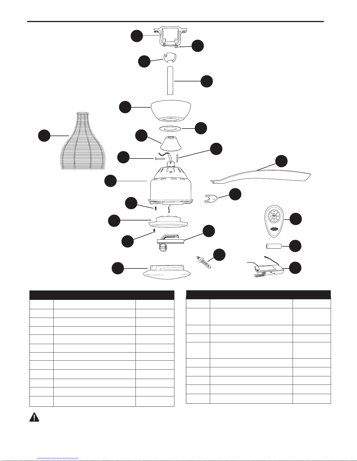
PACKAGE CONTENTS
V
C
N
K
A
B
I
D
M
L
G
E
J
P
T
O
PART DESCRIPTION QUANTITY
A
B
C
D
E
F
G
H
I
J
K
L
Downrod 1
Canopy
Mounting Bracket
Yoke Cover
Motor Housing
Blade Plate
Blade
Light Kit Fitter
Canopy Cover
Fitter Plate Screw
Hanging Ball
Pin (preassembled)
1
1
1
1
3
3
1
1
3
1
1
F
Q
H
12V Size A23
R
U
S
PART DESCRIPTION QUANTITY
M
Clip (preassembled)
N
Canopy Mounting Screw
O
P
Q
(preassembled)
Glass Shade
Shade Fitter
Remote Control
Transmitter
R 12-volt Battery
S Remote Control Receiver
T Shade Fitter Screw
U Halogen Bulb
V Wire Cage
1
2
1
1
1
1
1
3
1
1
IMPORTANT REMINDER: You must use the parts
provided with this fan for proper installation and safety.
5
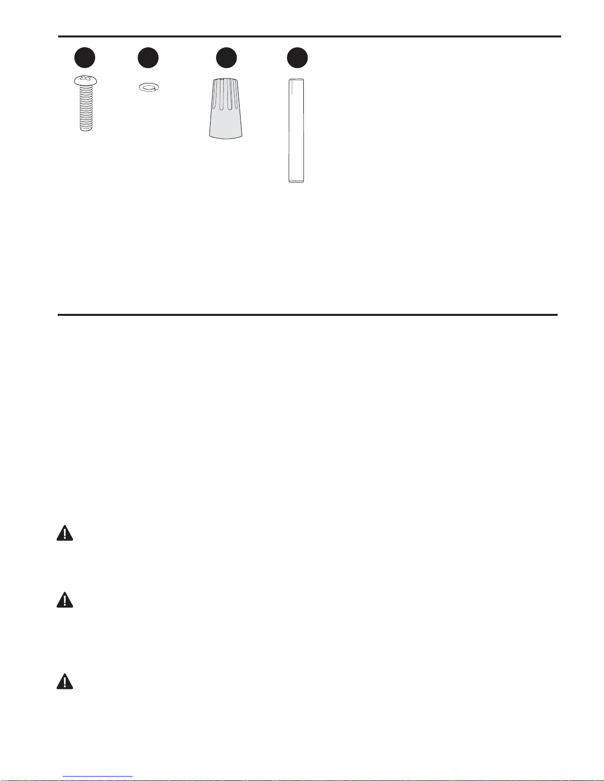
HARDWARE CONTENTS (shown actual size)
AA
BB CC
DD
Lock
Washer
Blade
Screw
Qty. 9
Qty. 9
E3 Wire
Connector
Qty. 10
Stop
Pin
Qty. 1
PREPARATION
Before beginning assembly of product, make sure all parts are present. Compare parts with package
contents list and hardware contents above. If any part is missing or damaged, do not attempt to
assemble the product. Contact customer service for replacement parts.
Estimated Assembly Time: 120 minutes
Tools Required for Assembly (not included): Electrical Tape, Phillips Screwdriver, Pliers, Safety
Glasses, Stepladder and Wire Strippers
Helpful Tools (not included): AC Tester Light, Tape Measure, Do-It-Yourself-Wiring Handbook
(available at Lowe’s) and Wire Cutters
Bulb Required (included): One 75-watt max. halogen bulb, size JD E11
DANGER: When using an existing outlet box, make sure the outlet box is securely attached to
the building structure and can support the full weight of the fan. Failure to do this can result in serious
injury or death. The stability of the outlet box is essential in minimizing wobble and noise in the fan
after installation is complete.
CAUTION: Be sure outlet box is properly grounded and that a ground wire (green or bare) is
present.
After opening top of carton, remove mounting hardware package from foam inserts. Remove motor
from packing and place on carpet or on foam to avoid damage to finish.
CAUTION: Carefully check all screws, bolts and nuts on fan motor assembly to ensure that they
are secured.
6
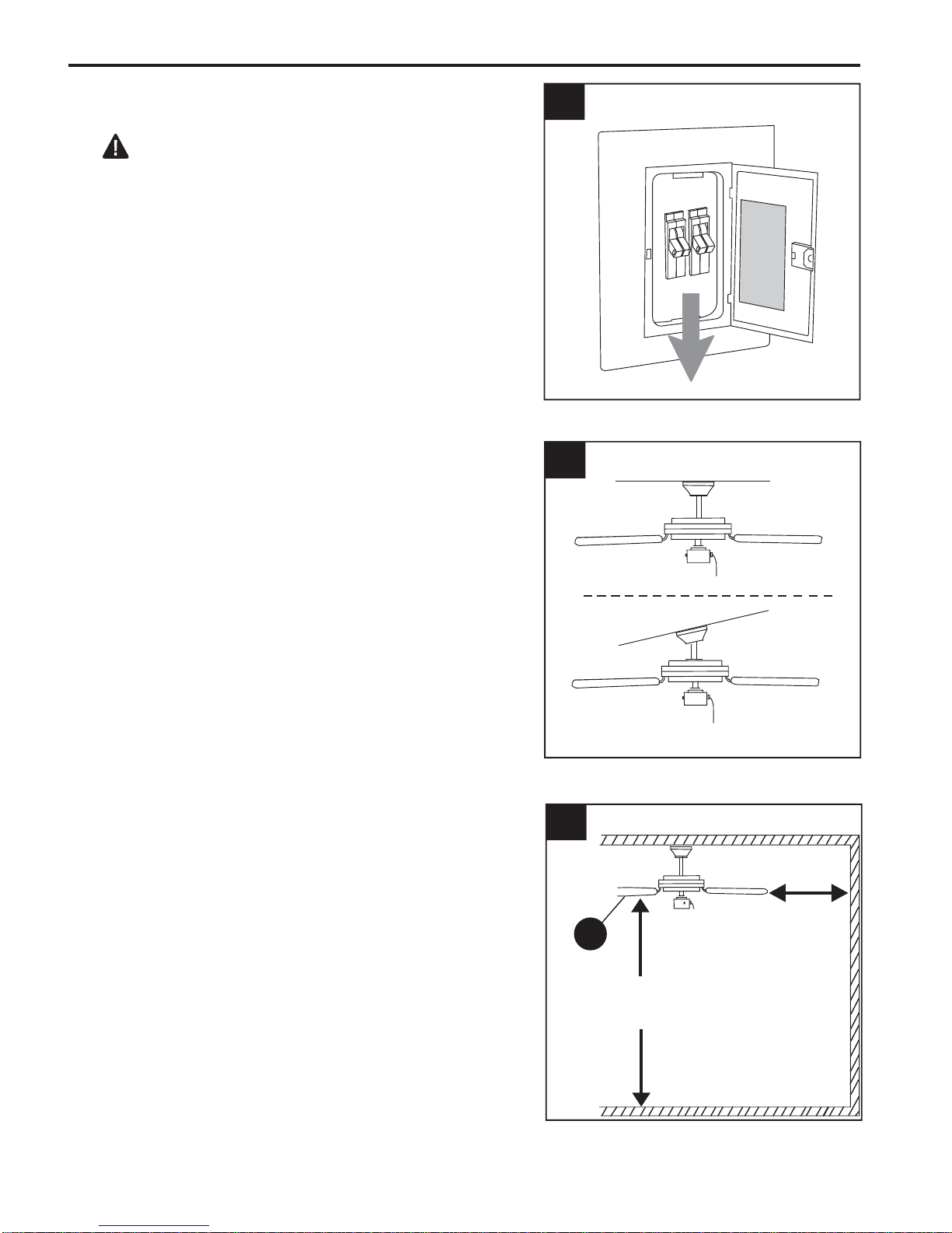
INITIAL INSTALLATION
1.
Turn off circuit breakers and wall switch to the fan
supply line leads. (Fig. 1)
DANGER: Failure to disconnect power supply
prior to installation may result in serious injury or
death.
Determine mounting method to use. (Fig. 2)
2.
A. Normal mount
B. Angle mount
Important: If using the angle mount, check to
make sure the ceiling angle is not steeper than 19°.
1
2
ON
ON
OFF
OFF
Check to make sure blades (G) are at least 30 in.
3.
from any obstruction. Check downrod (A) length to
ensure blades (G) are at least 7 ft. above the floor.
(Fig. 3)
3
3
A
B
G
30 in.
min.
7 ft.
min.
7
INITIAL INSTALLATION
Secure mounting bracket (C) to outlet box using
4.
screws, spring washers, and flat washers provided
with the outlet box. (Fig. 4)
*NOTE: It is very important that you use the proper
hardware when installing the mounting bracket (C)
as this will support the fan.
IMPORTANT: If using the angle mount, make sure
open end of mounting bracket (C) is installed
facing the higher point of the ceiling.
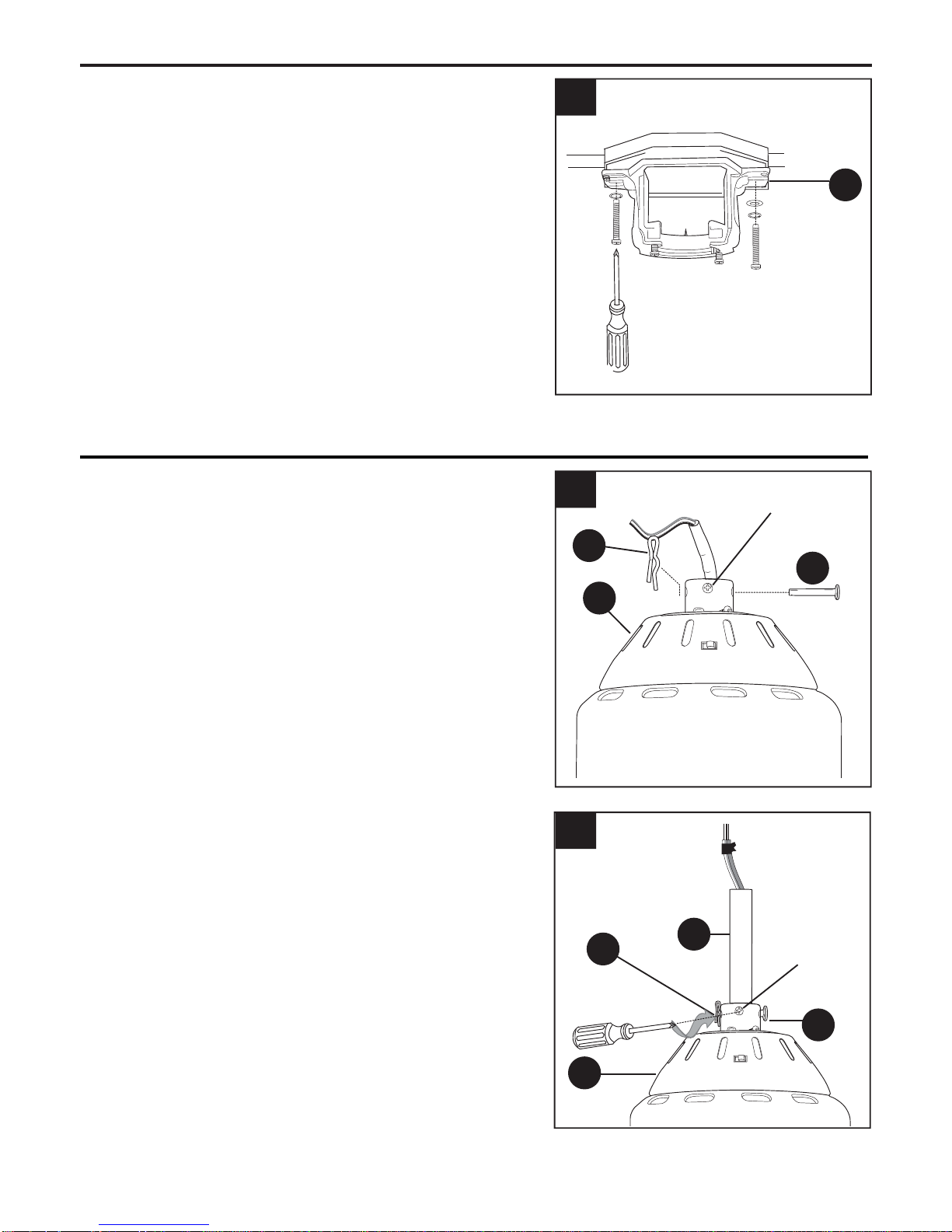
FAN MOUNTING
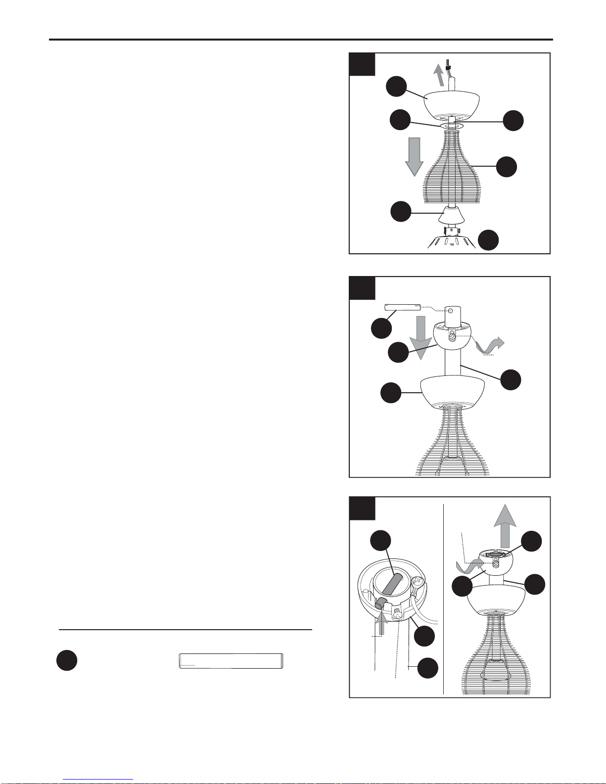
1.
Remove pin (L) and clip (M) from motor housing
yoke at top of motor housing (E) and partially
loosen set screws. (Fig. 1)
*Helpful Hint: Downrod style mounting is best
suited for ceilings 8 ft. (2.44 m) high or higher. For
taller ceilings you may want to use a longer
downrod (not included) than the one provided.
Angle style mounting is best suited for angled or
vaulted ceilings. A longer downrod is sometimes
necessary to ensure proper blade clearance.
4
1
C
Set
Screw
M
L
E
2.
Thread wires from motor housing (E) through
downrod (A). Slip downrod (A) into housing
yoke, align holes and re-install pin (L) and clip
(M). Tighten downrod (A) set screws and then
tighten nuts. (Fig. 2)
2
M
E
8
A
Set
Screw
L
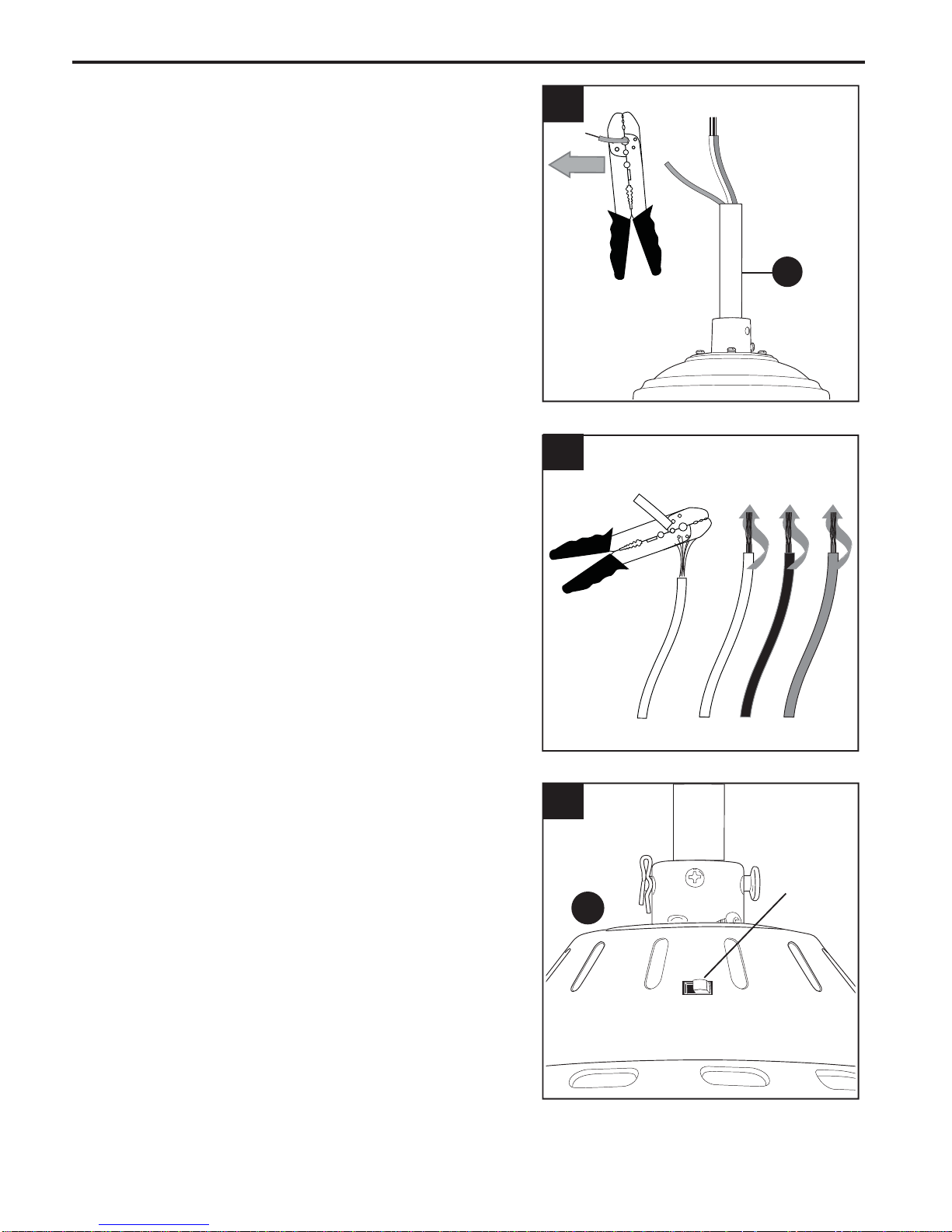
FAN MOUNTING
3.
Depending on the length of downrod (A) you
use, you may need to cut the lead wires back to
simplify the wiring. If you decide to cut back the
lead wires, it is suggested that you do so in the
following manner:
Take the lead wires and make sure that you
have pulled them all the way through the top of
the downrod (A). Start at the TOP of the
downrod (A) and measure 8 in. of lead wire, and
then cut the excess wire off with wire cutters (not
included). (Fig. 3)
NOTE: If you do not cut back the lead wires,
Steps 3 and 4 are not necessary and you may
proceed to Step 5 instead.
4.
If you decided to cut back the lead wires in
Step 3, strip 1/2 in. of insulation from end of
white wire. (Fig. 4) Twist stripped ends of each
strand of wire within the insulation with pliers
(not included). Repeat Step 4 for black, blue (if
applicable) and green wires.
3
A
4
5.
Set the reverse switch--located on the top of the
motor housing (E)--to the LEFT position for a
downward airflow to create a wind chill effect or
to the RIGHT position to create an upward
airflow that will help move hot air off the ceiling.
You will need to listen for a CLICK to be sure
the switch has been moved completely to the
left or completely to the right. (Fig. 5)
IMPORTANT: If you do not hear a click, the
switch is not set properly and the fan will not
function.
For further information on the reverse switch,
please see Step 2 on pages 18 and 19 in
“Operation Instructions for Remote Control and
Fan”.
5
Reverse
E
9
Switch
FAN MOUNTING
6.
Slide yoke cover (D) onto downrod (A) followed
by wire cage (V), canopy cover (I) and canopy
(B). [Note: Canopy cover (I) must be turned with
the shiny side toward the motor housing (E).]
(Fig. 6)
Locate hanging ball (K) and stop pin (DD). Check
7.
inside of hanging ball (K) with finger to be sure
surface is smooth; if it is not, partially loosen set
screw on side of hanging ball (K).
6
7A
DD
B
D
I
A
V
E
Thread wires from top of downrod (A) through
hanging ball (K) and then slide hanging ball (K)
onto downrod (A)--hanging ball (K) must be turned
with the rounded part facing the motor housing
(E). Slide stop pin (DD) through holes at top of
downrod (A), centering the stop pin (DD) in the
downrod (K) so equal amounts show on each side
of the downrod (A). Make sure all three wires
remain on the same side of the stop pin (DD). (Fig.
7A)
Locate slots inside hanging ball (K), turn hanging
ball (K) so slots align with stop pin (DD) and raise
hanging ball (K) to top of downrod (A). [NOTE: It is
extremely important the top of the hanging ball
(K) is flush with the top of the downrod (A); the
stop pin (DD) must sit COMPLETELY inside of the
slot in the hanging ball (K).] Securely tighten set
screw at top of downrod (A). (Fig. 7B)
Hardware Used
7B
Slot
DD
B
K
K
Set
Screw
K
Set Screw
A
DD
A
DD
Stop Pin x1
A
Set Screw
10
FAN MOUNTING
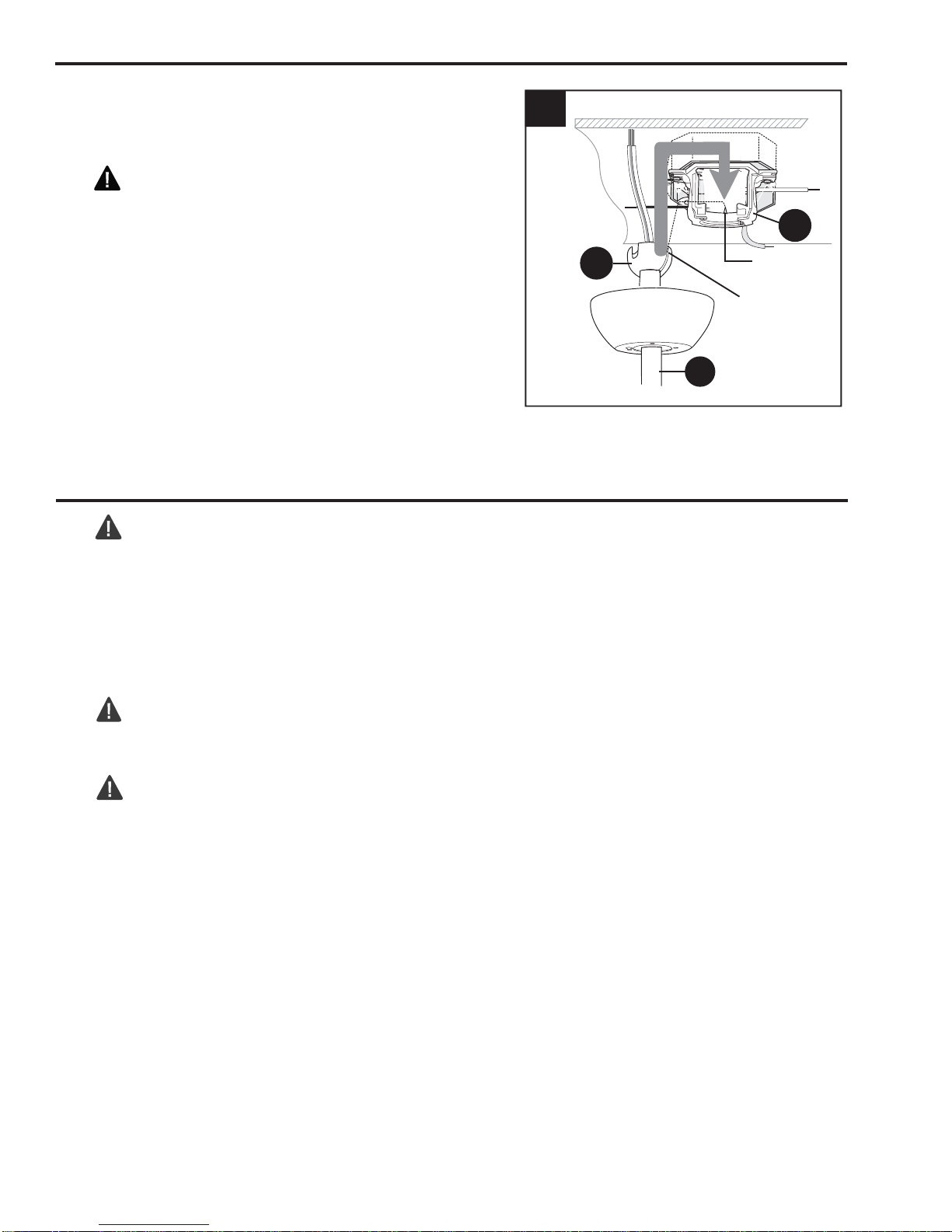
8.
Install hanging ball (K) on downrod (A) into
mounting bracket (C) opening. Align slot in hanging
ball (K) with tab in mounting bracket (C). (Fig. 8)
DANGER: Failure to align slot in hanging ball
(K) with tab may result in serious injury or death.
8
C
WIRING
WARNING: To reduce the risk of fire,
electrical shock, or personal injury, wire connectors
provided with this fan are designed to accept only
one 12-gauge house wire and two lead wires from
the fan. If your house wire is larger than 12-gauge
or there is more than one house wire to connect to
the two fan lead wires, consult an electrician for the
proper size wire connectors to use.
CAUTION: Be sure outlet box is properly
grounded and that a ground (green or bare) wire is
present.
K
Tab
Hanging
Ball Slot
A
WARNING: If house wires are different colors
than referred to in the following steps, stop
immediately. A professional electrician is
recommended to determine wiring.
NOTE: Black wire is hot power for fan. Blue wire is
hot power for light kit. White wire is common for fan
and light kit. Green or bare wire is ground.
NOTE: Please refer to installation and operating
instructions for remote control.
11
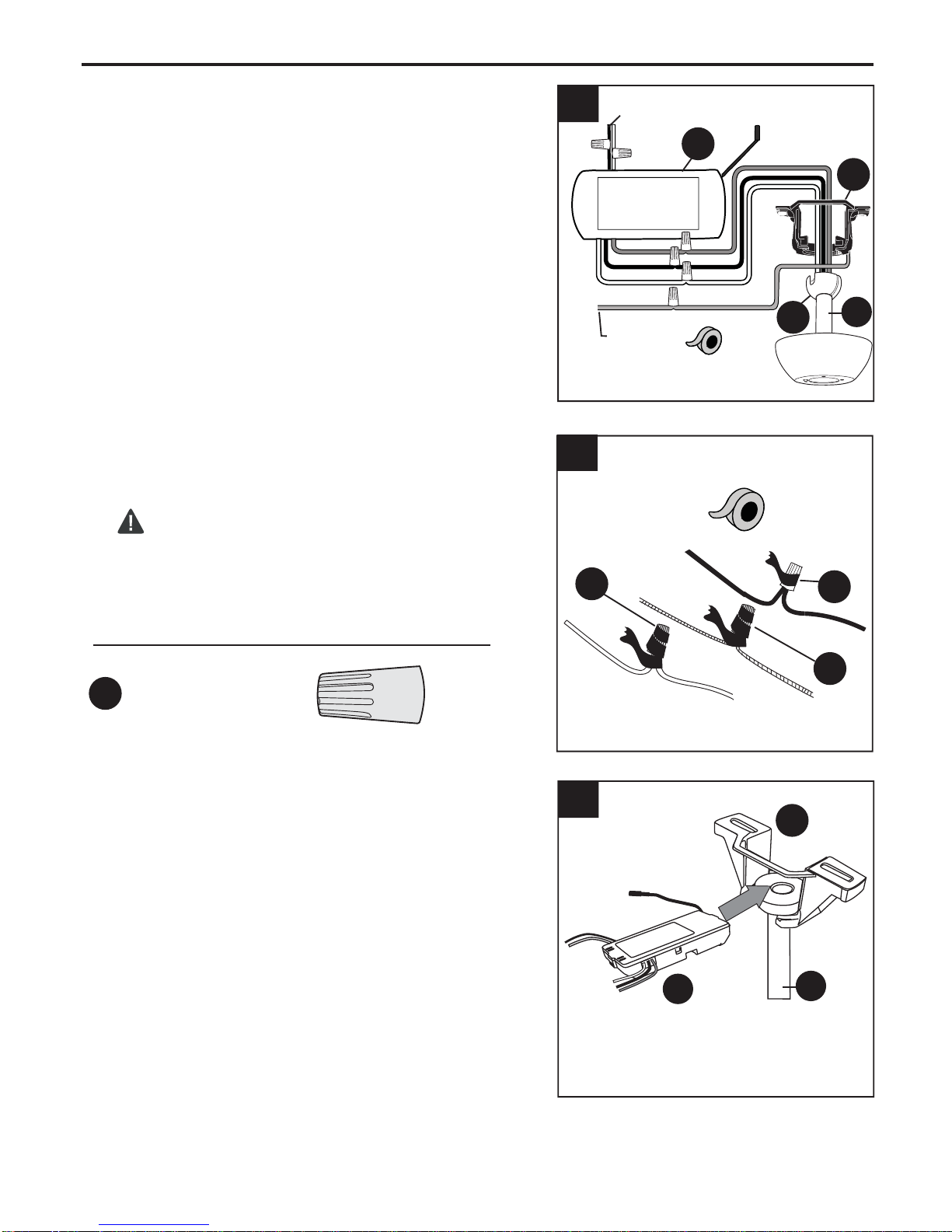
WIRING
Make the necessary wiring connections for remote
1.
control operation according to Fig. 1. For each wire
connection, use one of the wire connectors (CC)
provided, making sure to screw wire connector
(CC) on in a clockwise direction. [Make sure to
connect all GROUND (GREEN) wires together from
fan (on hanging ball (K) and mounting bracket (C))
to BARE/GREEN wire from ceiling.]
WIRING TIP: Wiring your fan's remote control
requires extreme patience. Take mandatory breaks
while wiring to allow your arms to rest.
Wrap electrical tape (not included) around each
2.
individual wire connector (CC) down to the wire as
shown in Fig. 2.
1
BLACK
BLACK
2
120 V Power
FROM CEILING
WHITE
WHITE
BLUE BLUE
BLACK
WHITE
BARE GREEN
AC SUPPLY
S
BLACK
WHITE
ANTENNA
K
C
A
WARNING: Make sure no bare wire or wire
strands are visible after making connections. Place
green and white connections on opposite side of
box from the black connections.
Hardware Used
CC
E3 Wire Connector x4
3.
Gently slide remote control receiver (S), smooth
side up, into mounting bracket (C). (Fig. 3) Turn
spliced/taped wires upward and gently push wires
and wire connectors (CC) into outlet box. Let
antenna from remote control receiver (S) hang to
the side.
Note: The remote control included with this fan
meets the following requirements:
a. Not for use with solid state fans.
b. Electrical rating: 120V / 60 Hz; motor
amps:1.5 MAX.;
light watts: 300 (Incandescent only).
Should you choose to use a different remote control
with this fan, it must also meet these same
requirements.
CC
3
Antenna
CC
CC
C
S
A
12
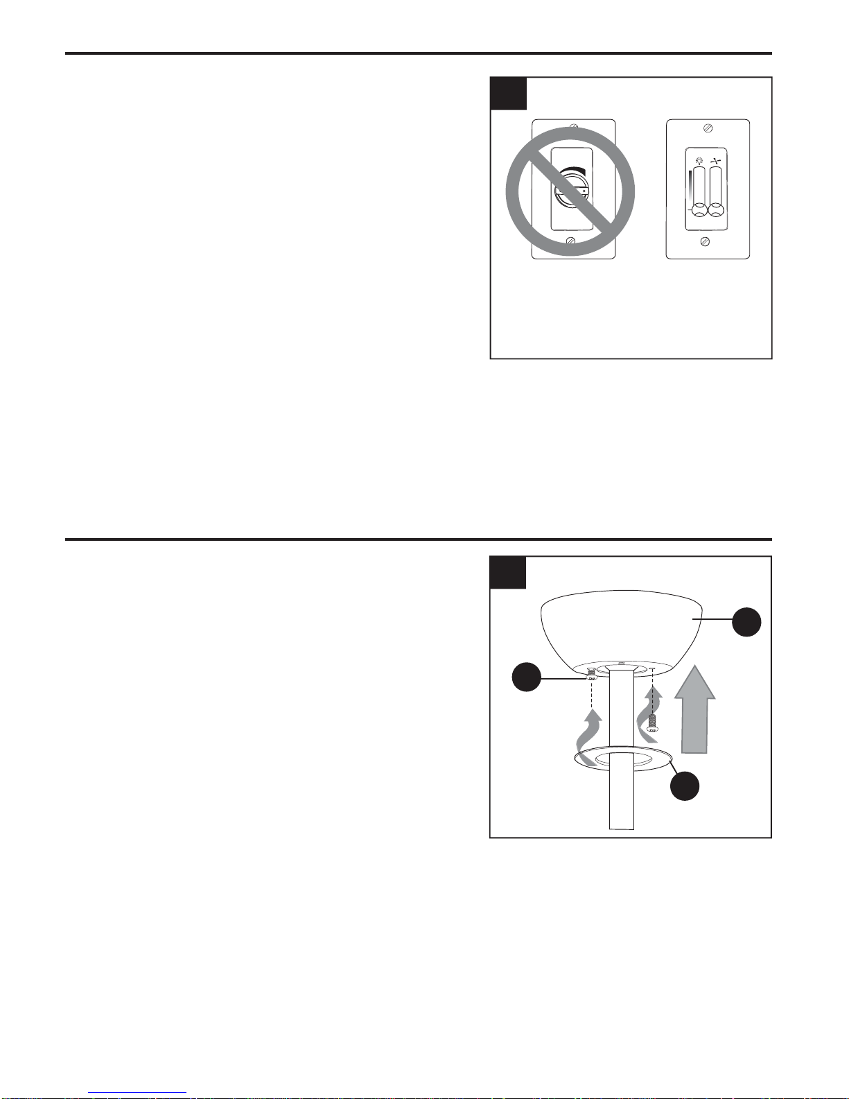
WIRING
4.
IMPORTANT: Using a full range dimmer switch (not
included) to control fan speed will cause a loud
humming noise from fan. To reduce the risk of fire or
electrical shock, do NOT use a full range dimmer
switch to control fan speed. (Fig. 4)
4
3
2
1
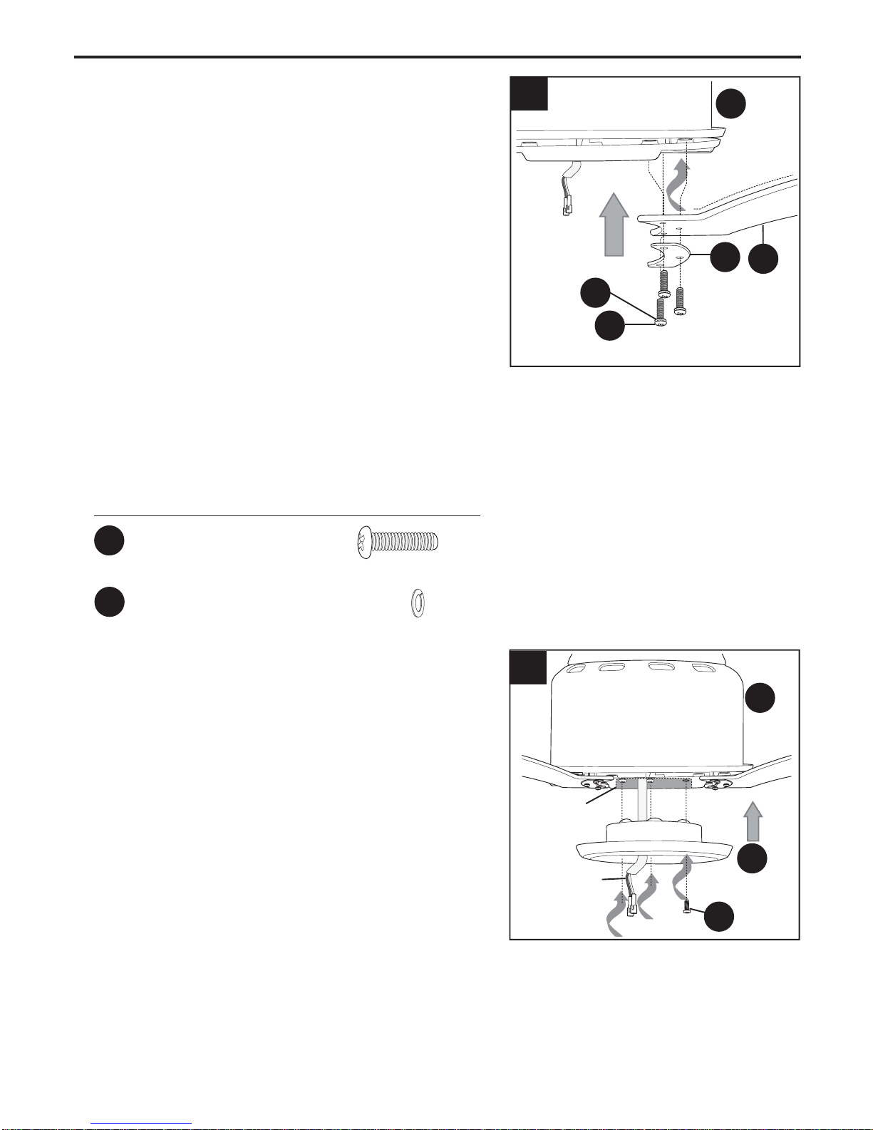
FINAL INSTALLATION
1.
Locate two canopy mounting screws (N) on
underside of mounting bracket (C) and remove
canopy mounting screw (N) closest to the open end
of the mounting bracket (C). Partially loosen the
other canopy mounting screw (N). Lift canopy (B) to
mounting bracket (C). Place rounded part of slotted
hole in canopy (B) over loosened canopy mounting
screw (N) in mounting bracket (C) and push up.
Twist canopy (B) to lock. Re-insert canopy mounting
screw (N) that was removed, and then tighten both
canopy mounting screws (N). Slide canopy cover (I)
up to canopy (B), aligning rounded part of slotted
holes in canopy cover (I) with screwheads in bottom
of canopy (B). Turn canopy cover (I) to the right
(clockwise) until it stops. (Fig. 1)
Dimmer
Switch
Speed
Switch
For illustrative purposes only--not
intended to cover all types of controls
1
B
N
I
13
FINAL INSTALLATION
Place one blade plate (F) over blade (G), aligning
2.
holes, with numbered side in blade plate (F) facing
up. After inserting one blade screw (AA), along
with one lock washer (BB), through center hole in
blade plate (F) and blade (G), align that blade
screw (AA) with center hole in one set of three
holes on underside of motor housing (E) to attach
blade plate (F) and blade (G) to motor. (Make
sure to attach blade (G) so that the curved part
of the blade (G) arcs UPWARD. Note label
indicating THIS SIDE UP.) Turn center blade
screw (AA) with fingers first, and then partially
insert the other two blade screws (AA), along with
lock washers (BB), with fingers also. Once all
three blade screws (AA) have been partially
inserted, tighten each blade screw (AA) with a
Phillips screwdriver (not included) starting with the
one in the middle. (Fig. 2) Repeat procedure with
remaining blades (G) and blade plates (F), making
sure to completely secure each blade (G) and
blade plate (F) before proceeding with the next.
2
BB
AA
E
Upward Arc
F
G
Hardware Used
AA
Blade Screw x9
BB
Lock Washer x9
Remove one fitter plate screw (J) from fitter plate
3.
(on underside of motor) and loosen the other two
fitter plate screws (J). Align slotted holes in middle
of shade fitter (P) with loosened screws in fitter
plate, allowing molex connections from motor
housing (E) to come through hole in middle of
shade fitter (P). Twist shade fitter (P) to lock.
Re-insert fitter plate screw (J) that was just
removed, and then tighten all three fitter plate
screws (J) securely. (Fig. 3)
3
E
Fitter
Plate
P
Molex
Connections
J
14
 Loading...