

Harbor Breeze E-CM54RBZ5CRCI Installation Manual
SOS ITEM/ARTICULO SOS #0125086
MONTCLAIR/CEILING FAN
MONTCLAIR
Harbor Breeze® is a registered trademark of LF, LLC.
All Rights Reserved.
Federal regulations require ceiling fans with light kits manufactured or imported after
January 1, 2009, to limit total wattage consumed by the light kit to 190W. Therefore,
this fan is equipped with a wattage limiting device.
/VENTILADOR DE TECHO (página 13)
MODEL/MODELO #E-CM54RBZ5CRCI
E192641
WARNINGS
• READ AND SAVE THESE INSTRUCTIONS.
• Read this manual carefully and completely before attempting to assemble, install or operate this product.
• Be sure you read and understand the Safety Precautions on page 3 of these instructions.
• Do not discard fan carton or foam inserts. Should this fan need to be returned to the factory for repairs, it must be
shipped in its original packaging to ensure proper protection against damage that might exceed the initial cause for
return.
• CAUTION: Before proceeding, be sure to shut off electricity at main switch or circuit breaker in order to avoid
electrical shock.
• WARNING: To reduce the risk of fire or electric shock, do not use the fan with any solid state speed
control device or control fan speed with a full range dimmer switch.
• WARNING: To reduce the risk of fire, electric shock, or personal injury, do not bend the blade arms when
installing them, balancing the blades, or cleaning the fan. Do not insert foreign objects between the rotating fan
blades. Mount to outlet box marked "ACCEPTABLE FOR FAN SUPPORT" and use mounting screws provided with
the outlet box. Most outlet boxes commonly used for the support of lighting fixtures are not acceptable for fan
support and may need to be replaced. Consult a qualified electrician if in doubt.
Questions, problems, missing parts? Before returning to your retailer, call or contact our customer service
department at 1-800-527-1292, 8:30 a.m.-5:00 p.m., CST, Monday-Friday.

TABLE OF CONTENTS
Safety Information ........................…………………………………………………………………….……...……..….3
Package Contents .............................…………………………………………………………………………...……..4
Preparation .........................................….…………………..……………………….…………….………………..5
Initial Installation .........................................…………………………………………………...........…………...…..5
Fan Mounting ..........................………......................………………………………….………………………...….6
Wiring for Remote Control and Fan .............................................................………………………………......6 - 7
Final Installation ............………………….…………….……………………….…………….……...............…….7 - 8
Automated Learning Process/Activating Code ....................................................……………………………………..…..9
Remote Control and Fan Operation .......................................................................................................9 - 10
Lighted Housing Bulb Replacement ......................................................................................................................10
Care and Maintenance ........................………………………………………………………..…………......…..10
Troubleshooting ............................................…………………………………………………..………....…….....11
Warranty ........................…………………………………….…………………………………………..………....... 12
2
SAFETY INFORMA TION
READ AND SAVE THESE INSTRUCTIONS
Please read and understand this entire manual before attempting to assemble, install or operate the product. If you
have any questions regarding the product, please call customer service at 1-800-527-1292, 8:30 a.m.-5:00 p.m.,
CST, Monday-Friday.
1. Before you begin installing the fan, disconnect the power by removing fuses or turning off circuit breakers
.
2. CAUTION: Read all instructions and safety information before installing your new fan. Review the
accompanying assembly diagrams.
3.
CAUTION: To avoid personal injury, the use of gloves may be necessary while handling fan parts with
sharp edges.
4. Make sure that all electrical connections comply with local codes, ordinances, the National Electrical Code and
ANSI/NFPA 70-1999. Hire a qualified electrician or consult a do-it-yourself wiring handbook, available at Lowe's,
if you are unfamiliar with installing electrical wiring.
5. Make sure the installation site you choose allows a minimum clearance of 7 feet from the blades to the floor and
at least 30 in. from the end of the blades to any obstruction.
6. WARNING: To reduce the risk of fire, electrical shock, or personal injury, mount fan to outlet box marked
"ACCEPTABLE FOR FAN SUPPORT" and use mounting screws provided with the outlet box. Most outlet boxes
commonly used for the support of lighting fixtures are not acceptable for fan support and may need to be
replaced. Consult a qualified electrician if in doubt. Secure the box directly to the building structure. The outlet
box and its support must be able to support the moving weight of the fan (at least 35 lbs.). Do NOT use a plastic
outlet box.
7. After you install the fan, make sure that all connections are secure to prevent the fan from falling.
8. WARNING: To reduce the risk of fire, electrical shock, or personal injury, wire connectors provided with
this fan are designed to accept only one 12 gauge house wire and two lead wires from the fan. If your house
wire is larger than 12 gauge or there is more than one house wire to connect to the two fan lead wires, consult
an electrician for the proper size wire connectors to use.
9. WARNING: To reduce the risk of fire or electric shock, do not use the fan with any solid state
speed control device or control fan speed with a full range dimmer switch.
10. WARNING: To reduce the risk of fire, electric shock, or personal injury, do not bend the blade arms when
installing them, balancing the blades, or cleaning the fan. Do not insert objects between the rotating fan blades.
11. WARNING: To reduce the risk of personal injury, use only parts provided with this fan. The use of parts
OTHER than those provided with this fan will void the warranty.
12. The net weight of this fan including the light kit is: 29.21 lbs. (13.25 kg).
3
PACKAGE CONTENTS
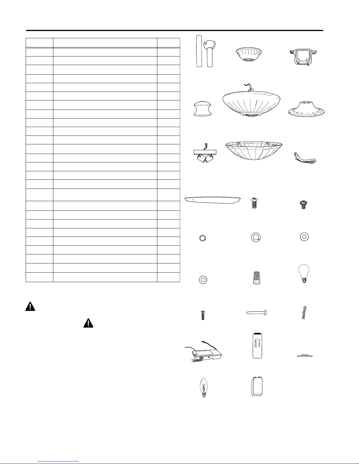
Part Description Quantity
A Downrod 2
B Canopy 1
C Mounting Bracket 1
D Yoke Cover 1
E* Motor Housing 1
F Shade Fitter 1
G Light Kit Fitter 1
H Glass Shade 1
I Blade Arm 5
J Blade 5
K Motor Screw (in motor) 10
L 3/16 Blade Screw (in hardware pack) 15
M 5/32 Lock Washer (in hardware pack) 2
N 5.4M/M Lock Washer
(in motor and hardware pack) 12
O Blade Washer (in hardware pack) 15
P 4M Washer (in hardware pack) 2
Q E3 Wire Connector
6 in remote control hardware pack)
(4 in regular hardware pack; 10
R* Candelabra Base Bulb 2
S Canopy Mounting Screw (attached to mounting bracket) 2
T Pin (in motor housing yoke) 1
U Clip (attached to pin) 1
V Remote Control Receiver 1
W Remote Control Transmitter 1
X Canopy Cover (in hardware pack) 1
Y* Candelabra Base Bulb
(pre-installed in lighted housing) 6
Z* 9-volt Battery (in hardware pack) 1
AB C
DE F
G
J
H
K
MN
I
L
O
IMPORTANT REMINDER: You must use
the parts provided with this fan for proper
installation and safety.
NOTE:
For replacement parts, call our customer service department
at 1-800-527-1292, 8:30 a.m.-5:00 p.m., CST, Monday-Friday.
When ordering parts, please have the Model # or Item # of the
fan available, which can be found on page 1.
* The parts denoted with an asterisk (*) above are NOT
replaceable.
P
S
V
Y
QR
TU
W
X
Z
4
PREPARATION
1. Before beginning assembly and installation of product, make sure all parts are present. Compare parts with
"Package Contents" list and diagrams on the previous page. If any part is missing or damaged, do not attempt to
assemble, install or operate the product. Contact customer service for replacement parts as indicated at the bottom
of page 4.
Estimated Assembly Time: 120 minutes
Tools Required for Assembly (not included): electrical tape, Phillips screwdriver, pliers, safety glasses, stepladder
and wire strippers
Helpful Tools (not included): AC tester light, tape measure, do-it-yourself-wiring handbook, available at Lowe’s, and
wire cutters
Bulbs Required: 6 candelabra base 15-watt max. bulbs (included), for lighted housing
2 candelabra base 60-watt max. bulbs (included), for light kit
DANGER: When using an existing outlet box, make sure the outlet box is securely attached to the building
structure and can support the full weight of the fan. Failure to do this can result in serious injury or death. The
stability of the outlet box is essential in minimizing wobble and noise in the fan after installation is complete.
CAUTION: Be sure outlet box is properly grounded and that a ground (green or bare) wire is present.
2. After opening top of carton, remove mounting hardware package from foam inserts. Remove motor from packing
and place on carpet or on foam to avoid damage to finish.
CAUTION: Carefully check all screws, bolts and nuts on fan motor assembly to ensure that they are secured.
INITIAL INSTALLATION
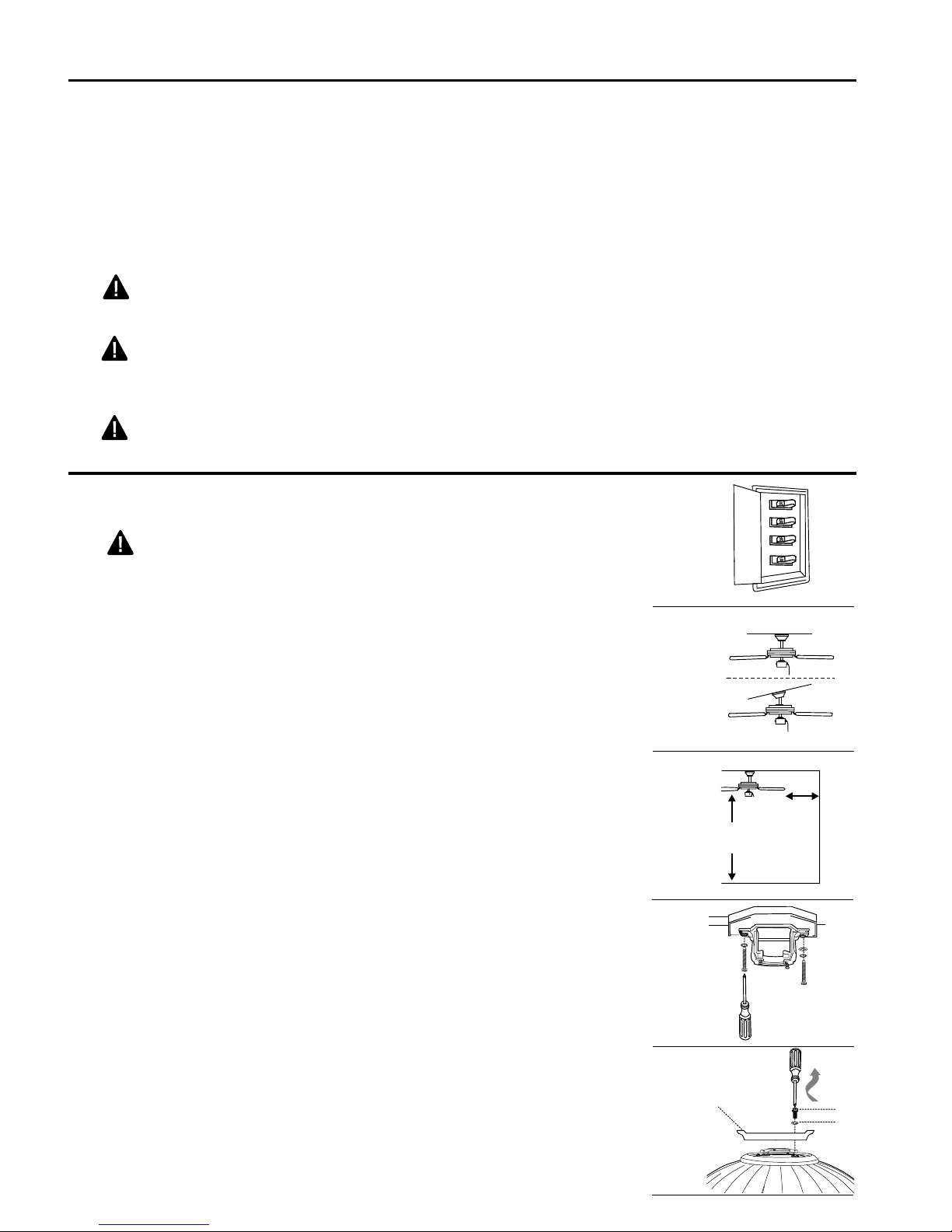
1. Turn off circuit breakers and wall switch to the fan supply line
leads. [Fig. 1]
DANGER: Failure to disconnect power supply prior to
installation may result in serious injury or death.
Fig. 1
2. Determine mounting method to use. [Fig. 2]
A. Normal mount
B. Angle mount
Important: If using the angle mount, check to make sure the
ceiling angle is not steeper than 19°.
A
3. Check to make sure blades (J) are at least 30 in. from any
obstruction. Check downrod (A) length to ensure blades (J) are at
least 7 ft. above the floor. [Fig. 3]
4. Secure mounting bracket (C) to outlet box using screws, spring
washers, and flat washers provided with the outlet box. [Fig. 4]
*Note: It is very important that you use the proper hardware when
installing the mounting bracket (C) as this will support the fan.
Important: If using the angle mount, make sure open end of
mounting bracket (C) is installed facing the higher point of the
ceiling.
5. Remove motor screws (K) and lock washers (N) from underside
of motor. Remove and discard blue motor stabilization plate. [Fig. 5]
Fig. 2
Fig. 3
Fig. 4
stabilization
plate
B
7 ft.
min.
J
30 in.
min.
C
K
N
E
5
Fig. 5
FAN MOUNTING
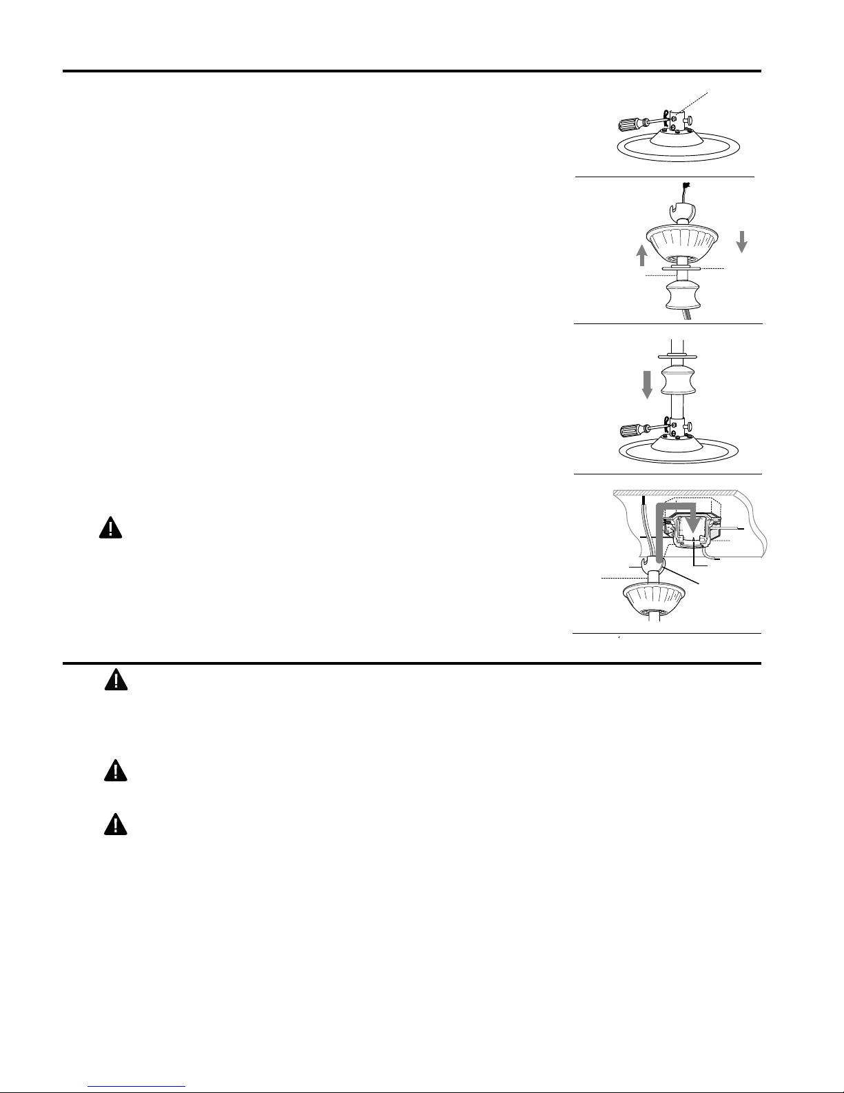
1. Remove pin (T) and clip (U) from motor housing yoke at top of motor
housing (E) and partially loosen set screws. [Fig. 1]
*Helpful Hint: Downrod style mounting is best suited for ceilings 8 ft.
high or higher. For taller ceilings you may want to use a longer
downrod (not included) than the ones supplied. Angle style mounting is
best suited for angled or vaulted ceilings. Longer downrods are
sometimes necessary to ensure proper blade clearance.
2. Choose downrod (A) length you wish to use.* If you chose to use the
12 in. downrod (A), remove hanging ball from the 6 in. downrod (A) and
attach to the 12 in. downrod (A). Insert downrod (A) through canopy
(B), canopy cover (X), and yoke cover (D). [Note: Canopy cover (X)
must be turned with the shiny side toward the motor housing (E).]
Thread wires from motor housing (E) through downrod (A). [Fig. 2]
3. Slip downrod (A) into housing yoke, align holes and re-install pin
(T) and clip (U). Tighten downrod (A) set screws and then tighten
nuts. Slide yoke cover (D) down until it rests on top of motor
housing (E). [Fig. 3]
4. Install ball end of downrod (A) into mounting bracket (C)
opening. Align slot in ball with tab in mounting bracket (C). [Fig. 4]
Fig. 1
Fig. 2
Fig. 3
U
T
Screw
E
B
Set
A
X
D
A
D
U
T
E
DANGER: Failure to align slot in ball with tab may result in
serious injury or death.
WIRING FOR REMOTE CONTROL AND FAN (continued on next page)
WARNING: To reduce the risk of fire, electrical shock, or personal
injury, wire connectors provided with this fan are designed to accept only one
12 gauge house wire and two lead wires from the fan. If your house wire is
larger than 12 gauge or there is more than one house wire to connect to the
two fan lead wires, consult an electrician for the proper size wire connectors
to use.
WARNING: If house wires are different colors than referred to in the
next steps, stop immediately. A professional electrician is recommended to
determine wiring.
CAUTION: Be sure wiring box is properly grounded and that a
ground wire (green or bare) is present.
Note: Black wire is hot power for fan. Orange wire is hot power for lighted
housing. Blue wire is hot power for light kit. White wire is common for fan
and light kit. Green wire is ground.
Note: Please refer to installation and operating instructions for remote
control.
A
Fig. 4
Ball
B
C
Tab
Hanging
Ball Slot
6
WIRING FOR REMOTE CONTROL AND FAN (continued from previous page)
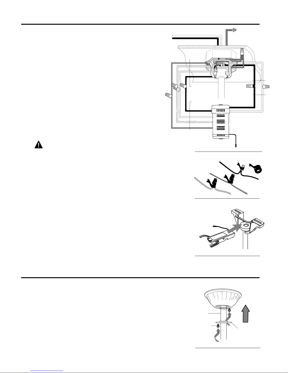
1. Make the necessary wiring connections for remote operation
according to Fig. 1. For each wire connection, use one of the
wire connectors (Q) provided, making sure to screw wire
connector (Q) on in a clockwise direction. [Make sure to
connect all GROUND (GREEN) wires together from fan (on
downrod and mounting bracket) to BARE/GREEN wire from
ceiling.]
WIRING TIP: Wiring your fan's remote control requires extreme
patience. Take mandatory breaks while wiring to allow your
arms to rest.
2. Tape wire connectors (Q) and wires together with electrical
tape. [Fig. 2]
Warning: Make sure no bare wire or wire strands are
visible after making connections. Place green and white
connections on opposite side of box from the black, orange and
blue (if applicable) connections.
white supply wire
black supply wire
blue
white
black
orange
from fan
from receiver
black
white
orange
blue
Fig. 1
ground
(green or bare)
ground (green
or bare)
black
from ceiling
from receiver
black
AC IN L
white
AC IN N
V
antenna
Q
white
3. Gently slide remote control receiver (V), flat side up, into
mounting bracket (C). Turn spliced/taped wires upward and
gently push wires and wire connectors (Q) into outlet box. Let
antenna from receiver (V) hang to the side. [Fig. 3]
Note: The remote control included with this fan meets the
following requirements:
a. Not for use with solid state fans.
b. Electrical rating: 120V / 60 Hz; motor amps:1.0 MAX.;
light watts: 300 (incandescent only).
FINAL INSTALLATION (continued on next page)
1. Locate two canopy mounting screws (S) on underside of
mounting bracket (C) and remove screw (S) closest to the open
end of of the hanging bracket (C). Partially loosen the other
screw (S). Lift canopy (B) to mounting bracket (C). Place
rounded part of slotted hole in canopy (B) over loosened screw
(S) in hanging bracket (C) and push up. Twist canopy (B) to
lock. Re-insert screw (S) that was removed, and then tighten
both screws (S) securely. Slide canopy cover (X) up to canopy
(B), aligning rounded part of slotted holes in canopy cover (X)
with screwheads in bottom of canopy (B). Turn canopy cover
(X) to the right (clockwise) until it stops. [Fig. 1]
Fig. 2
Fig. 3
Fig. 1
Q
Antenna
A
S
Q
C
V
A
B
X
7
FINAL INSTALLATION (continued from previous page)
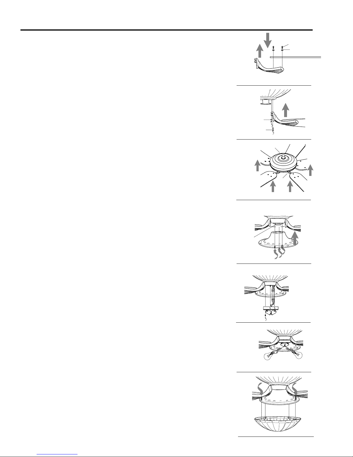
2. Position blade arm (I) under blade (J) and secure blade arm (I)
with screws (L) and washers (O). Do not tighten screws (L) until
each screw (L) has been started. Then, tighten each screw (L)
starting with the center screw (L). Repeat for the remaining blades
(J). [Fig. 2]
L
O
J
3. Locate motor screws (K) and lock washers (N) that were
previously removed on page 5. (Additional motor screws (K) and
lock washers (N) are in hardware pack.) Insert only one motor
screw (K), along with lock washer (N), through blade arm (I) to
attach blade arm (I) to motor and partially tighten the motor screw
(K). Repeat with remaining blade arms (I). [Fig. 3]
4. Place remaining lock washers (N) and insert motor screws (K).
Repeat with remaining blade arms (I). Tighten all motor screws
(K) securely. [Fig. 4]
5. Remove one screw on fitter plate (on underside of motor) and
loosen the other two screws. Align slotted holes in shade fitter (F)
with loosened screws in fitter plate. Twist shade fitter (F) to lock
and re-install screw that was previously removed. Tighten all
screws securely. [Fig. 5]
6. Partially loosen two screws on the underside of the shade
fitter (F) and remove the other screw. Connect WHITE wire from
light kit fitter (G) to WHITE wire from motor housing (E). Connect
BLACK wire from light kit fitter (G) to BLACK wire from motor
housing (E). Make sure that molex connections snap together
securely.
Carefully arrange wiring within light kit fitter (G). Align slotted
holes in light kit fitter (G) with loosened screws in shade fitter (F).
Twist light kit fitter (G) to lock. Re-insert screw that was removed
and tighten all screws securely. [Fig. 6]
Fig. 2
Fig. 3
Fig. 4
fitter
plate
Fig. 5
Fig. 6
I
E
N
K
I/J
E
I
J
E
F
E
F
G
7. Install two candelabra base 60 watt max. bulbs (R) included.
[Fig. 7]
Important: When replacing bulbs, allow bulb(s) and glass shade
(H) to cool before touching them.
8. Remove one screw from inside glass shade (H) and
partially loosen the other three screws. Align the three
loosened screws in glass shade (H) with slotted holes
in shade fitter (F). Twist glass shade to lock. Re-insert
screw that was previously removed and secure all four
screws with a Phillips screwdriver. [Fig. 8]
Tip:Use a short Phillips screwdriver for easier access
to screws in shade fitter (F).
E
F
R
Fig. 7
E
F
Fig. 8
H
8
 Loading...