

Harbor Breeze CSD52FBZ5C4S, CSD52BNK5C4S Installation Manual
ITEM #18037
18038
Harbor Breeze® is a registered trademark
of LF, LLC. All Rights Reserved.
CHESHIRE II CEILING FAN
MODEL #CSD52FBZ5C4S
CSD52BNK5C4S
español p. 17
Questions, problems, missing parts? Before returning to your retailer, call our customer
service department at 1-800-527-1292, 8:30 a.m.-5 p.m., CST, Monday-Friday.
E124404
1

TABLE OF CONTENTS
Safety Information ........................………………………………………………………......….3
Package Contents .............................…………………………………………………………..4
Hardware Contents .............................…………………………………………………...........5
Preparation .......................................….…………………..……………………….….....5 - 6
Initial Installation ............................................……………………...………..................6 - 7
Wiring ...............................................................................................……......................8 - 9
Final Installation ............………………….………….....................................................9 - 12
Using Fan Without Light Kit (Optional) ......................................................................................12
Fan Operation ..............................................……………………………......................12 - 13
Care and Maintenance .......................………………………......………...….....…..............13
Troubleshooting ...........................................………...……………………..….........…........14
Warranty ........................…………………………………….………………..............…......….15
Replacement Parts List .......................………………………......………...….....….............16
2
SAFETY INFORMATION
READ AND SAVE THESE INSTRUCTIONS
Please read and understand this entire manual before attempting to assemble, install or operate
the product. If you have any questions regarding the product, please call customer service at
1-800-527-1292, 8:30 a.m.-5:00 p.m., CST, Monday-Friday.
1. Before you begin installing the fan, disconnect the power by removing fuses or turning off
circuit breakers.
2. CAUTION: Read all instructions and safety information before installing your new fan.
Review the accompanying assembly diagrams.
3. WARNING: To avoid personal injury, the use of gloves may be necessary while handling
fan parts with sharp edges.
4. Make sure that all electrical connections comply with local codes, ordinances, the National
Electrical Code and ANSI/NFPA 70-199. Hire a qualified electrician or consult a do-it-yourself
wiring handbook, available at Lowe's, if you are unfamiliar with installing electrical wiring.
5. Make sure the installation site you choose allows a minimum clearance of 7 feet from the
blades to the floor and at least 30 in. from the end of the blades to any obstruction.
6. WARNING: To reduce the risk of fire, electrical shock, or personal injury, mount fan to
outlet box marked "ACCEPTABLE FOR FAN SUPPORT" and use mounting screws provided with
the outlet box. Most outlet boxes commonly used for the support of lighting fixtures are not
acceptable for fan support and may need to be replaced. Consult a qualified electrician if in
doubt. Secure the box directly to the building structure. The outlet box and its support must be
able to support the moving weight of the fan (at least 35 lbs.). Do NOT use a plastic outlet box.
7. After you install the fan, make sure that all connections are secure to prevent the fan from
falling.
8. WARNING: To reduce the risk of fire, electrical shock, or personal injury, wire connectors
provided with this fan are designed to accept only one 12 gauge house wire and two lead wires
from the fan. If your house wire is larger than 12 gauge or there is more than one house wire to
connect to the two fan lead wires, consult an electrician for the proper size
wire connectors to use.
9. WARNING: To reduce the risk of fire or electric shock, do not use the fan with
any solid state speed control device or control fan speed with a full range dimmer switch.
10. WARNING: To reduce the risk of fire, electric shock, or personal injury, do not bend
the blade arms when installing them, balancing the blades, or cleaning the fan. Do not insert
objects between the rotating fan blades.
11. WARNING: To reduce the risk of personal injury, use only parts provided with this
fan. The use of parts OTHER than those provided with this fan will void the warranty.
12. The net weight of this fan including the light kit is: 18,3 lbs. (8,3 kg).
3
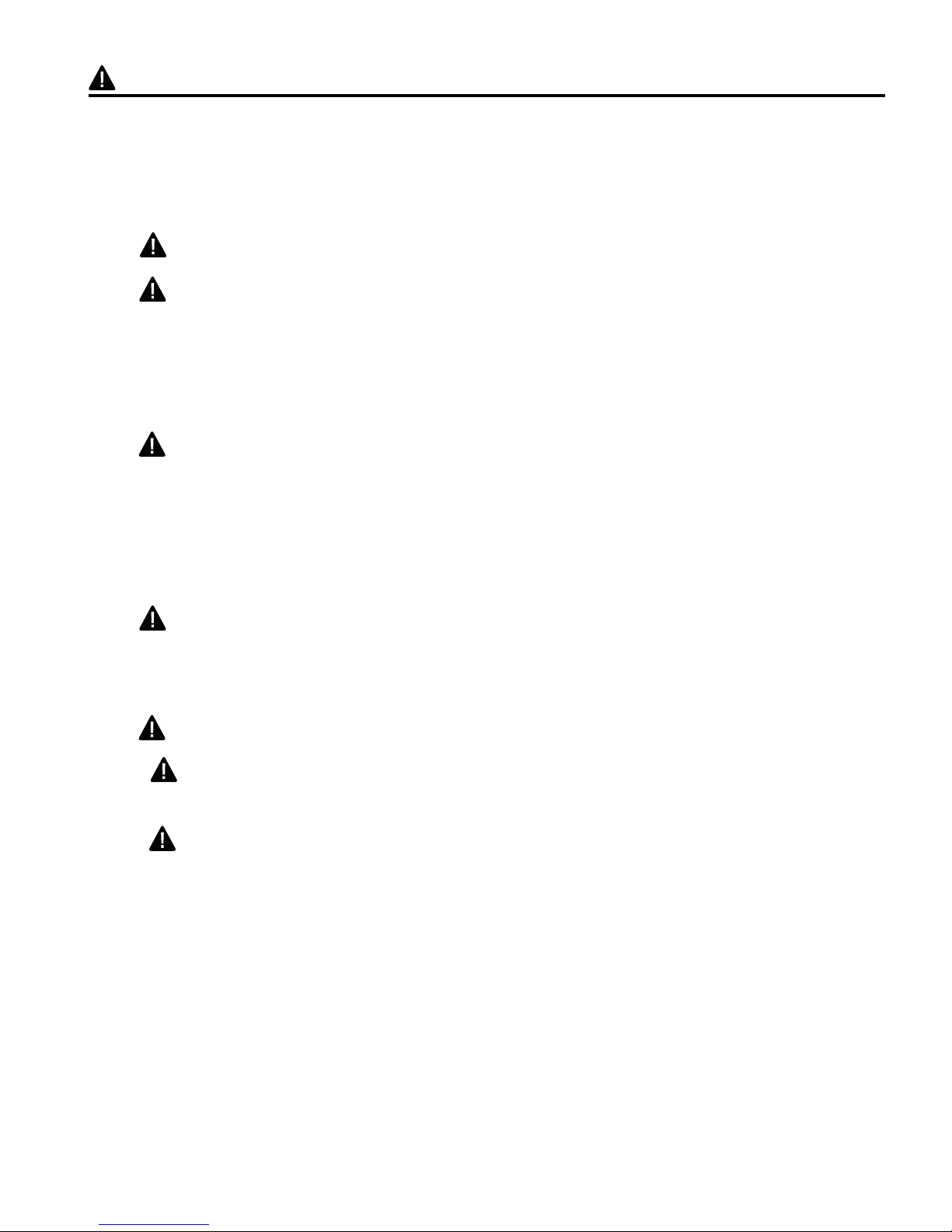
PACKAGE CONTENTS
Part Description Quantity
A Motor Housing 1
B Mounting Bracket 1
C Extra Switch Housing 1
D Motor Assembly 1
E Light Kit Fitter 1
F Glass Shade 4
G
Blade Arm 5
H Blade 5
I
Candelabra Base Bulb 4
J Pull Chain Extension 2
(in hardware pack)
K Plastic Lock Tab 1
L Socket Ring 4
(attached to light kit fitter)
A
D
B
E
C
F
IMPORTANT REMINDER: You must
use the parts provided with this fan for
proper installation and safety.
I
L
G
H
J K
4
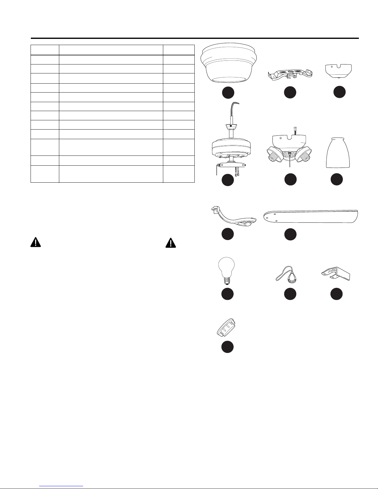
HARDWARE CONTENTS
Part Description Quantity Part Shown to Size
Motor Screw (10 in motor; 1 in hardware pack) 11
AA
3/16 Blade Screw (in hardware pack) 16
BB
5.4M/M Lock Washer (10 in motor; 11
CC
1 in hardware pack)
Blade Washer (in hardware pack) 16
DD
EE
E3 Wire Connector (in hardware pack) 4
Motor Housing Mounting Screw
FF
4
(attached to mounting bracket)
PREPARATION
1. Before beginning assembly, installation or operation of product, make sure all parts are
present. Compare parts with package contents list and diagram above. If any part is missing or
damaged, do not attempt to assemble, install or operate the product.
Estimated Assembly Time: 120 minutes
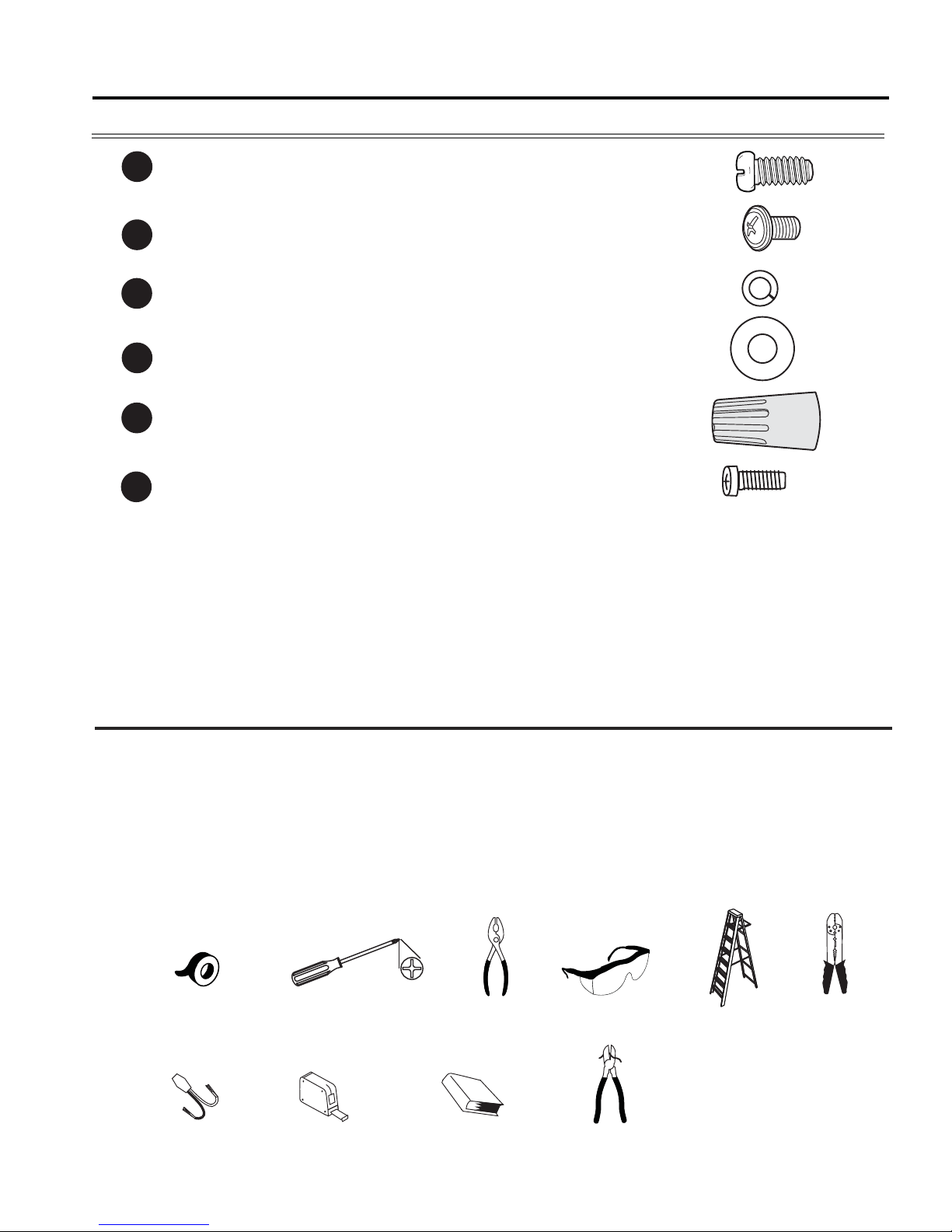
Tools Required for Assembly (not included): electrical tape, Phillips screwdriver, pliers, safety
glasses, stepladder, wire strippers.
Helpful Tools (not included): A/C tester light, tape measure, do-it-yourself wiring handbook
(available at Lowe’s), wire cutters.
5
PREPARATION
Bulbs Required (included): 4 candelabra base 60 watt max. bulbs
A-15
DANGER: When using an existing outlet box, make sure the outlet box is securely attached
to the building structure and can support the full weight of the fan. Failure to do this can result in
serious injury or death. The stability of the outlet box is essential in minimizing wobble and noise
in the fan after installation is complete.
CAUTION: Be sure outlet box is properly grounded and that a ground (green or bare) wire is
present.
2. After opening top of carton, remove mounting hardware package from foam inserts. Remove
motor from packing and place on carpet or on foam to avoid damage to finish.
CAUTION: Carefully check all screws, bolts and nuts on fan motor assembly to ensure that
they are secured.
INITIAL INSTALLATION
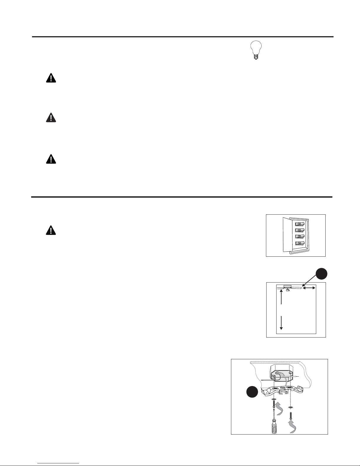
1. Turn off circuit breakers and wall switch to the fan supply
Fig. 1
line leads. (Fig. 1)
DANGER: Failure to disconnect power supply prior to
installation may result in serious injury or death.
2. Check to make sure blades (H) will be at least 30 in. from
any obstruction and at least 7 ft. above the floor. (Fig. 2)
3. Secure mounting bracket (B) to outlet box
using screws, spring washers, and flat
washers provided with the outlet box. (Fig. 3)
Pull wires from outlet box through center hole
in mounting bracket (B).
*Note: It is very important that you use the
proper hardware when installing the mounting
bracket (B) as this will support the fan.
Fig. 2
7 ft.
min.
Fig. 3
H
30 in.
min.
B
6
INITIAL INSTALLATION
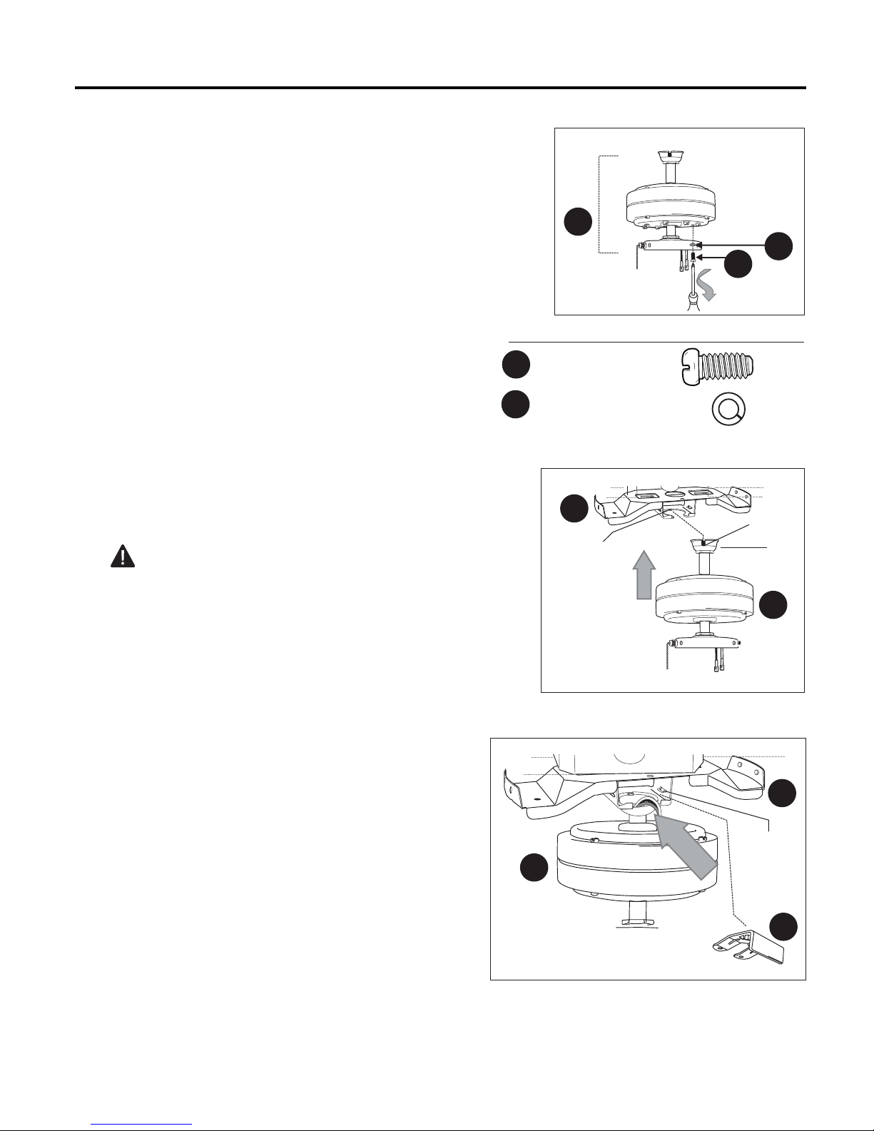
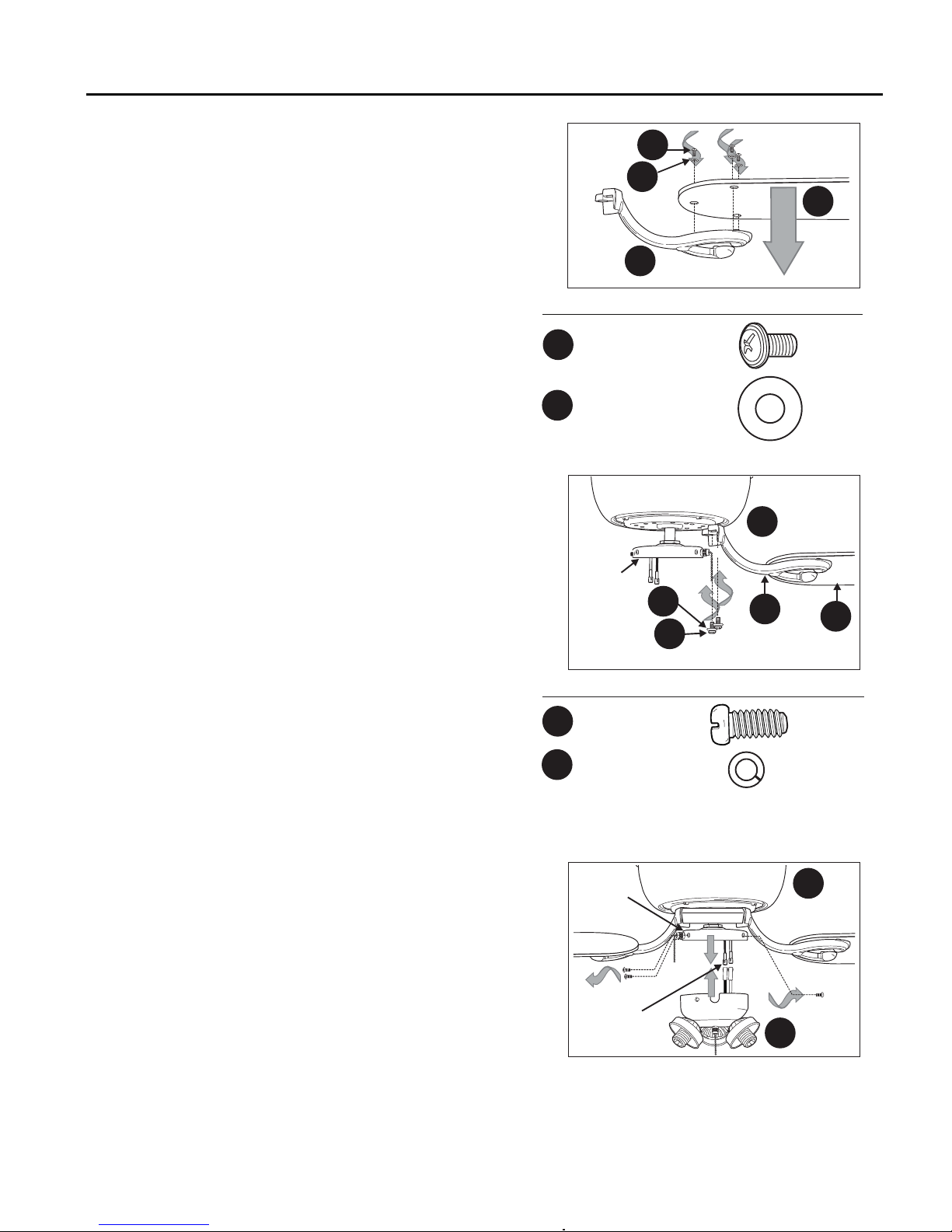
4. Remove motor screws (AA) and lock
washers (CC) from underside of motor--save
to attach blade arms (G) later on. If there are
also plastic motor blocks, discard them at
this time. (Fig. 4)
5. Install ball end of motor assembly (D) into
mounting bracket (B) opening. Align slot in ball
with tab in mounting bracket (A). (Fig. 5)
DANGER: Failure to align slot in ball with
tab in mounting bracket (B) may result in serious
injury or death.
Fig. 4
Motor
D
AA
Hardware Used
Motor Screw x 10
AA
CC
5.4 M/M Lock Washer x 10
Fig. 5
B
Slot
Tab
CC
Ball
D
6. To ensure the safety of the installation and to
prevent the motor assembly (D) from becoming
or coming loose, use the plastic lock tab (K).
Slide plastic lock tab (K) under bracket tabs so
that it will snap into place. (Fig. 6)
IMPORTANT: Keep in mind that it will require
some force to fully insert the plastic lock tab
(K) so that it does not move or come out
once in the correct position.
Fig. 6
B
Bracket
Tab
D
K
7
WIRING
WARNING: To reduce the risk of fire, electrical
shock, or personal injury, wire connectors provided with
this fan are designed to accept only one 12 gauge house
wire and two lead wires from the fan. If your house wire is
larger than 12 gauge or there is more than one house wire
to connect to the two fan lead wires, consult an electrician
for the proper size wire connectors to use.
CAUTION: Be sure wiring box is properly grounded
and that a ground (green or bare) wire is present.
WARNING: If house wires are different colors than
referred to in the following steps, stop immediately. A
professional electrician is recommended to determine wiring.
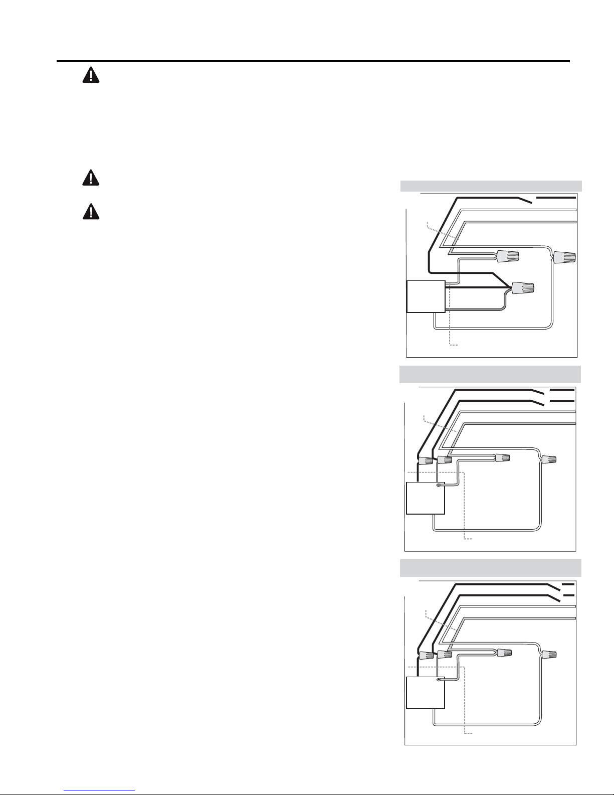
1. Choose wiring diagram (Fig. 1A, Fig. 1B or Fig. 1C) that
fits your situation and make appropriate wiring connections
as follows: [NOTE: For each wire connection below, use
one of the wire connectors (EE) provided, making sure to
screw wire connector (EE) on in a clockwise direction.]
1A. FAN AND LIGHT CONTROLLED BY PULL
CHAINS: Connect BLACK and BLUE wire from fan to
BLACK wire from ceiling. Connect WHITE wire from fan
to WHITE wire from ceiling. Connect GROUND
(GREEN) wire together from mounting bracket to
BARE/GREEN wire from ceiling. (Fig. 1A)
1B. FAN CONTROLLED BY PULL CHAIN, LIGHT BY
WALL SWITCH: If you intend to control the fan light with
a separate wall switch, connect BLACK wire from fan to
BLACK wire from ceiling. Connect BLUE wire from fan
to the BLACK wire from the independent wall switch for
the light. Connect WHITE wire from fan to WHITE wire
from ceiling. Connect GROUND (GREEN) wire together
from mounting bracket to BARE/GREEN wire from
ceiling. (Fig. 1B)
1C. FAN AND LIGHT CONTROLLED BY TWO WALL
SWITCHES: If you intend to control the fan and light with
separate wall switches, connect BLACK wire from fan to
BLACK wire from the independent wall switch for the
fan. Connect BLUE wire from fan to the BLACK wire
from the other independent wall switch for the light.
Connect WHITE wire from fan to WHITE wire from
ceiling. Connect GROUND (GREEN) wire together from
mounting bracket to BARE/GREEN wire from ceiling.
(Fig. 1C)
FAN AND LIGHT CONTROLLED BY PULL CHAINS
Fig. 1A
120 V Power
FROM
CEILING
FAN
FAN CONTROLLED BY PULL CHAIN, LIGHT BY
WALL SWITCH
Fig. 1B
120 V Power
FROM
CEILING
BLACK
FAN
FAN AND LIGHT CONTROLLED BY TWO WALL
SWITCHES
Fig. 1C
120 V Power
FROM
CEILING
BLACK
BLACK
WHITE
GROUND/GREEN (BARE)
GREEN
BLACK
BLUE
FROM FAN
BLACK
BLACK (WALL SWITCH)
WHITE
GROUND/GREEN (BARE)
BLUE
BLUE
GREEN
FROM FAN
BLACK (WALL SWITCH)
BLACK (WALL SWITCH FOR LIGHT)
WHITE
GROUND/GREEN (BARE)
GREEN
WHITE
WHITE
WHITE
WHITE
WHITE
Note: Black wire is hot power for fan. Blue wire is hot
power for light kit. White wire is common for fan and light
kit. Green or bare wire is ground.
FAN
FROM FAN
WHITE
8
WIRING
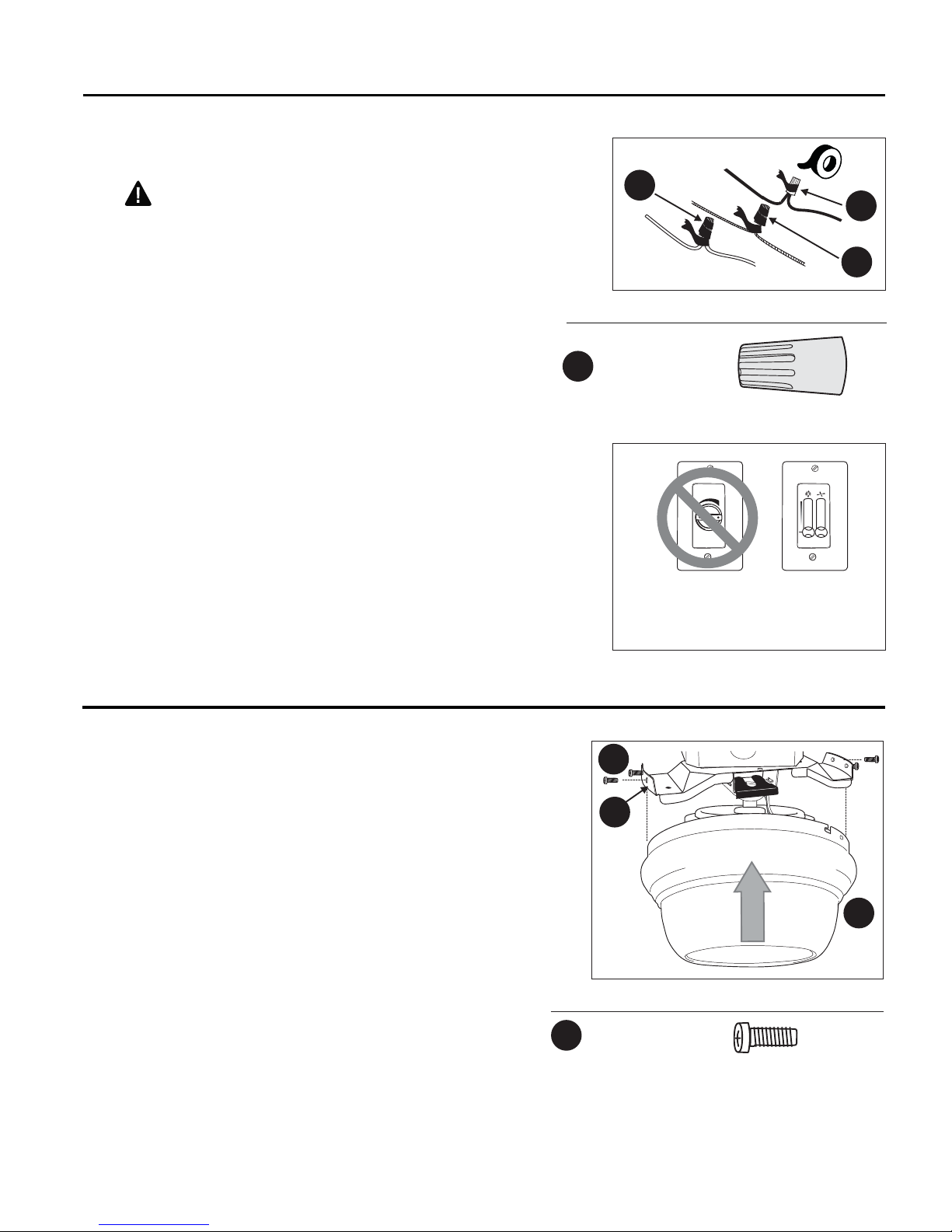
2. Wrap electrical tape around each wire connector
(EE) down to the wire as shown in Fig. 2.
WARNING: Make sure no bare wire or wire
strands are visible after making connections. Place
green and white connections on opposite side of box
from the black and blue (if applicable) connections.
Turn spliced/taped wires upward and gently push
wires and wire connectors (EE) into outlet box.
IMPORTANT: Using a full range dimmer switch to
control fan speed will cause a loud humming noise
from fan. To reduce the risk of fire or electric shock,
do NOT use a full range dimmer switch to control fan
speed. (Fig. 3)
Fig. 2
EE
Hardware Used
E3 Wire Connector x 4
EE
Fig. 3
3
2
1
EE
N
EE
FINAL INSTALLATION
1. Temporarily raise motor housing (A) to mounting
bracket (B) to determine which two screws (FF) align
with slotted holes in motor housing (A) and partially
loosen these two screws (FF). Remove the other two
screws (FF). Now, lift motor housing (A) to mounting
bracket (B) again, aligning slotted holes in motor
housing (A) with loosened screws (FF) in mounting
bracket (B). Twist motor housing (A) to lock. Re-insert
screws (FF) that were previously removed. Tighten all
four screws (FF) securely. (Fig. 1)
Dimmer
Switch
For illustrative purposes only--not
intended to cover all types of controls
Fig. 1
Speed
Switch
FF
B
Hardware Used
Motor Housing x 4
FF
Mounting Screw
A
9
FINAL INSTALLATION
Fig. 2
2. Partially insert three blade screws (BB), along with
three blade washers (DD), to attach one blade arm
(G) to a blade (H). Then, tighten each blade screw
(BB), starting with the one in the middle (Fig. 2)
Repeat with remaining blades (H).
3. Locate motor screws (AA) and lock washers (CC)
that were removed in Step 4 on page 7.
Insert one motor screw (AA), along with lock a
washer (CC), through one blade arm (G) to attach
blade arm (G) to motor. Partially tighten motor screw
(AA). Now, insert another motor screw (AA), along
with lock washer (CC), to secure blade arm (G).
Tighten both motor screws (AA) securely. (Fig. 3)
Note: For easy access to motor screws (AA), turn
motor so that the flat part of the switch housing plate
aligns with the two motor screw (AA) holes on blade
arm (G).
BB
DD
G
Hardware Used
3/16 Blade Screw x 15
BB
Blade Washer x 15
DD
Fig. 3
A
Switch
Housing
Plate
CC
G
AA
Hardware Used
Motor Screw x 10
AA
H
H
Repeat Step 3 with remaining blade arms (G),
making sure to completely secure each blade arm
(G) before proceeding with the next.
4. If you wish to USE the light kit, remove three
screws from switch housing plate on underside of
motor. Locate BLUE and WHITE wires in switch
housing plate labeled “FOR LIGHT” and remove
cardboard label and plastic from these two wires.
Connect WHITE wire from light kit fitter (E) to WHITE
wire from switch housing plate. Connect BLACK wire
from light kit fitter (E) to BLUE wire from switch
housing plate. Make sure that molex connections are
secure. (Fig. 4) Continue with Step 5.
If you do NOT wish to use the light kit, please go
to section entitled “Using Fan Without Light Kit” on
page 12.
CC
5.4 M/M Lock Washer x 10
Fig. 4
Switch
Housing
Plate
Molex
Connections
10
A
E
 Loading...