

Harbor Breeze CE-CSD42AB5C3, CE-CSD42LW5C3 User Manual
ITEM #0317058
0317060
CHESHIRE II CEILING FAN
Harbor Breeze® is a registered trademark
of LF, LLC. All Rights Reserved.
MODEL #CE-CSD42AB5C3
CE-CSD42LW5C3
Français p. 18
Federal regulations require ceiling fans with light kits manufactured or imported after
January 1, 2009, to limit total wattage consumed by the light kit to 190W. Therefore,
this fan is equipped with a wattage limiting device.
ATTACH YOUR RECEIPT HERE
Serial Number
Questions, problems, missing parts? Before returning to your retailer, call our customer
service department at 1-800-527-1292, 8:30 a.m. - 5 p.m., CST, Monday-Friday.
E124404
Purchase Date
1
TABLE OF CONTENTS
Safety Information ........................……………………………………………………….....2 - 3
Package Contents .............................…………………………………………………………..4
Hardware Contents .............................…………………………………………………...........5
Preparation .......................................….…………………..……………………….…..........5
Initial Installation ............................................……………………...………..................6 - 8
Wiring ...............................................................................................……....................8 - 10
Final Installation ............………………….…………...................................................10 - 12
Installing Fan Without Included Light Kit (Optional) ….…............................................
Operation Instructions ..............................................……………………….................13 - 14
Care and Maintenance .......................………………………......………...….....…..............15
...........
13
Troubleshooting ...........................................………...……………………..….........….15 - 16
Warranty ........................…………………………………….………………..............…......….16
Replacement Parts List .......................………………………......………...….....….............17
SAFETY INFORMATION
READ AND SAVE THESE INSTRUCTIONS
Please read and understand this entire manual before attempting to assemble, install or operate the
product. If you have any questions regarding the product, please call customer service at
1-800-527-1292, 8:30 a.m.- 5:00 p.m., CST, Monday - Friday.
• Do not discard fan carton or foam inserts. Should this fan need to be returned to the factory for
repairs, it must be shipped in its original packaging to ensure proper protection against damage that
might exceed the initial cause for return.
• Make sure that all electrical connections comply with local codes, ordinances, the National Electrical
Code and ANSI/NFPA 70-1999. Hire a qualified electrician or consult a do-it-yourself wiring handbook,
available at Lowe's, if you are unfamiliar with installing electrical wiring.
• Make sure the installation site you choose allows a minimum clearance of 7 feet from the blades to
the floor and at least 30 in. from the end of the blades to any obstruction.
• After you install the fan, make sure that all connections are secure to prevent the fan from falling.
• The net weight of this fan including the light kit is: 12.13 lbs. (5.5 kg).
2
SAFETY INFORMATION
WARNINGS
To reduce the risk of fire, electrical shock, or personal injury, mount fan to outlet box
marked "ACCEPTABLE FOR FAN SUPPORT" and use mounting screws provided with
the outlet box. Most outlet boxes commonly used for the support of lighting fixtures are
not acceptable for fan support and may need to be replaced. Consult a qualified electrician if in
doubt. Secure the outlet box directly to the building structure. The outlet box and its support must
be able to support the moving weight of the fan (at least 35 lbs.). Do NOT use a plastic outlet box.
To avoid personal injury, the use of gloves may be necessary while handling fan parts with
sharp edges.
To reduce the risk of fire, electrical shock, or personal injury, wire connectors provided with this
fan are designed to accept only one 12 gauge house wire and two lead wires from the fan. If your
house wire is larger than 12 gauge or there is more than one house wire to connect to the two fan
lead wires, consult an electrician for the proper size wire connectors to use.
To reduce the risk of fire or electrical shock, do not use the fan with any solid state speed
control device or control fan speed with a full range dimmer switch.
To reduce the risk of fire, electrical shock, or personal injury, do not bend the blade arms when
installing them, balancing the blades, or cleaning the fan. Do not insert objects between the
rotating fan blades.
To reduce the risk of personal injury, use only parts provided with this fan. The use of parts
OTHER than those provided with this fan will void the warranty.
This fan MUST be installed with the saftey cable provided with the fan. Failure to use the safety
cable provided may result in personal injury, damage to the fan or damage to other property.
CAUTIONS
Before proceeding, be sure to shut off electricity at main switch or circuit breaker in order to avoid
electrical shock.
Read all instructions and safety information before installing your new fan. Review the
accompanying assembly diagrams.
3
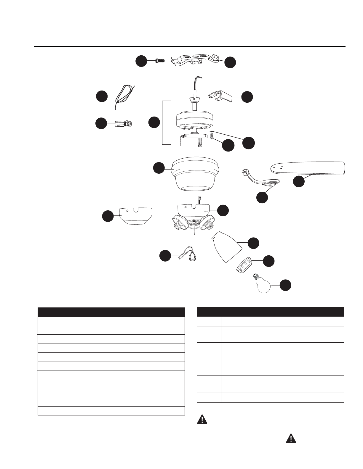
PACKAGE CONTENTS
N
B
M
Q
D
O
C
P
A
H
G
E
L
J
PART DESCRIPTION QUANTITY
A Motor Housing 1
B Mounting Bracket 1
C Plastic Lock Tab 1
D Motor Assembly 1
E Light Kit Fitter
1
F Glass Shade 3
G Blade Arm
5
H Blade 5
I Candelabra Base Bulb 3
J Pull Chain Extension 2
K Socket Ring
3
F
K
I
PART DESCRIPTION QUANTITY
L Extra Switch Housing
M Safety Cable
1
1
(preassembled)
N Motor Housing Mounting 4
Screw (preassembled)
O Motor Screw 10
(preassembled)
P
5.4 M/M Lock Washer 10
(preassembled)
Q
Vice (preassembled) 1
IMPORTANT REMINDER: You must
use the parts provided with this fan for
proper installation and safety.
4
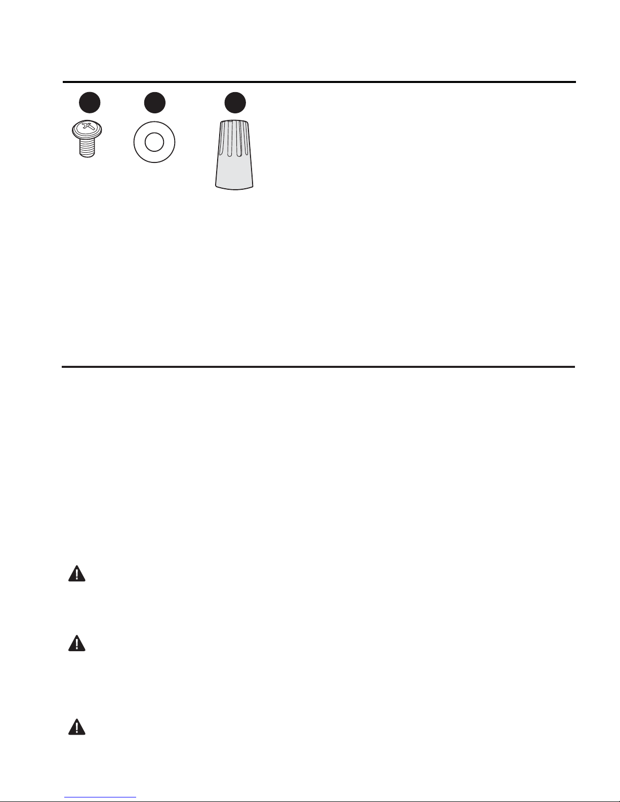
HARDWARE CONTENTS (shown actual size)
AA
Blade
Screw
Qty. 15
BB CC
Fiber
Blade
Washer
E3 Wire
Connector
Qty. 15
Qty. 4
PREPARATION
Before beginning assembly and installation of product, make sure all parts are present. Compare
parts with package contents list and hardware contents above. If any part is missing or
damaged, do not attempt to assemble the product. Contact customer service for replacement parts.
Estimated Assembly Time: 120 minutes
Tools Required for Assembly (not included): Electrical Tape, Phillips Screwdriver, Pliers, Safety
Glasses, Stepladder and Wire Strippers
Helpful Tools (not included): AC Tester Light, Tape Measure, Do-It-Yourself-Wiring Handbook
(available at Lowe’s) and Wire Cutters
Bulbs Required (included): 3 candelabra base 60-watt max. bulbs
DANGER: When using an existing outlet box, make sure the outlet box is securely attached to
the building structure and can support the full weight of the fan. Failure to do this can result in serious
injury or death. The stability of the outlet box is essential in minimizing wobble and noise in the fan
after installation is complete.
CAUTION: Be sure outlet box is properly grounded and that a ground wire (green or bare) is
present.
After opening top of carton, remove mounting hardware package from foam inserts. Remove motor
from packing and place on carpet or on foam to avoid damage to finish.
CAUTION: Carefully check all screws, bolts and nuts on fan motor assembly to ensure that they
are secured.
5
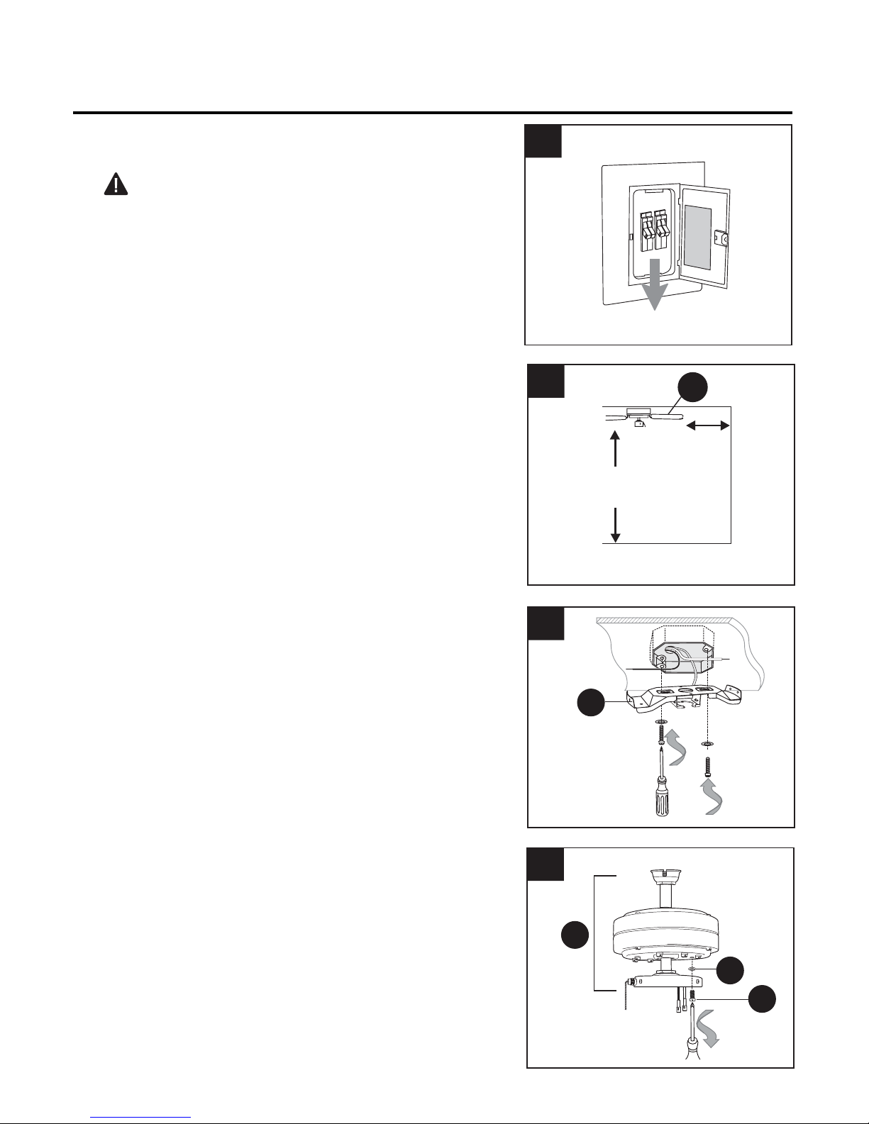
INITIAL INSTALLATION
1.
Turn off circuit breakers and wall switch to the fan
supply line leads. (Fig. 1)
DANGER: Failure to disconnect power supply
prior to installation may result in serious injury or
death.
2.
Check to make sure blades (H) are at least 30 in.
from any obstruction and at least 7 ft. above the
floor. (Fig. 2)
1
2
7 ft.
min.
ON
ON
OFF
OFF
H
30 in.
min.
3.
Secure mounting bracket (B) to outlet box using
screws, spring washers, and flat washers provided
with the outlet box. (Fig. 3) Pull wires from outlet
box through center hole in mounting bracket (B).
*Note: It is very important that you use the proper
hardware when installing the mounting bracket (B)
as this will support the fan.
4.
Remove motor screws (O) and 5.4 M/M lock
washers (P) from underside of motor and save for
blade arm (G) attachment later on. [If there are
plastic motor blocks installed with motor screws (O)
and 5.4 M/M lock washers (P), discard the plastic
motor blocks.] (Fig. 4)
3
B
4
D
P
O
6
 Loading...