

Harbor Breeze 41107, 41108, 40949, 40948 User Manual

Harbor Breeze® is a registered trademark
of LF, LLC. All Rights Reserved.
ITEM #0176493, 0179178, 0922357, 0922356
LANSING CEILING FAN
MODEL #40948, 40949, 41108, 41107
Español p. 21
ATTACH YOUR RECEIPT HERE
Purchase Date _________________________
Questions, problems, missing parts? Before returning to your retailer, call our customer
service department at 1-800-643-0067, 8 a.m. - 6 p.m., EST, Monday - Thursday,
8 a.m. - 5 p.m., EST, Friday.
BM18022
1

TABLE OF CONTENTS
Package Contents .................................................................3
Hardware Contents ................................................................4
Safety Information .................................................................5
Preparation ......................................................................6
Initial Installation ..................................................................7
Standard or Angled Mounting Instructions. . . . . . . . . . . . . . . . . . . . . . . . . . . . . . . . . . . . . . . . . . . . . . . 9
Closemount Instructions ...........................................................11
Wiring .........................................................................12
Final Installation. . . . . . . . . . . . . . . . . . . . . . . . . . . . . . . . . . . . . . . . . . . . . . . . . . . . . . . . . . . . . . . . . . 13
Operating Instructions .............................................................17
Care and Maintenance ............................................................18
Troubleshooting ..................................................................18
Limited Lifetime Warranty ..........................................................19
Replacement Parts List ............................................................20
2
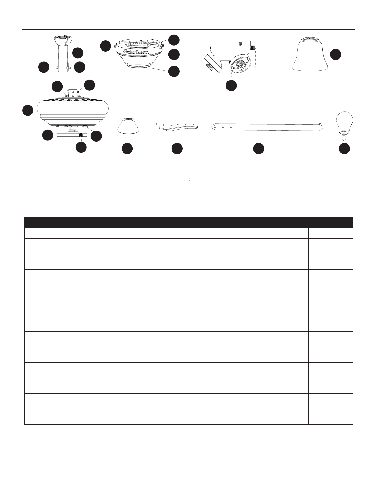
PACKAGE CONTENTS
R
A
D
E
H
E
CB
Q
P
F
F
G
I
I
J
O
S
K
K L M N
M
N
PART DESCRIPTION QUANTITY
A Downrod 1
B Downrod Pin (preassembled to Downrod [A]) 1
C Downrod Clip (preassembled to Downrod [A]) 1
D Mounting Bracket (preassembled to Canopy [E]) 1
E Canopy 1
F Canopy Cover (preassembled to Canopy [E]) 1
G Light Kit 1
H Glass Shade 3
I Motor Assembly 1
J Fitter Plate (preassembled to Motor Assembly [I]) 1
K Yoke Cover 1
L Blade Arm 5
M Blade 5
N Bulb 3
O Motor Screw (preassembled to Motor Assembly [I]) 10
P Set Screw (preassembled to Motor Assembly [I]) 2
Q Phillips-head Closemount Screw (preassembled to Motor Assembly [I]) 3
R Mounting Bracket Screw (preassembled to Mounting Bracket [D]) 4
S Fitter Plate Screw (preassembled to Fitter Plate [J]) 3
3
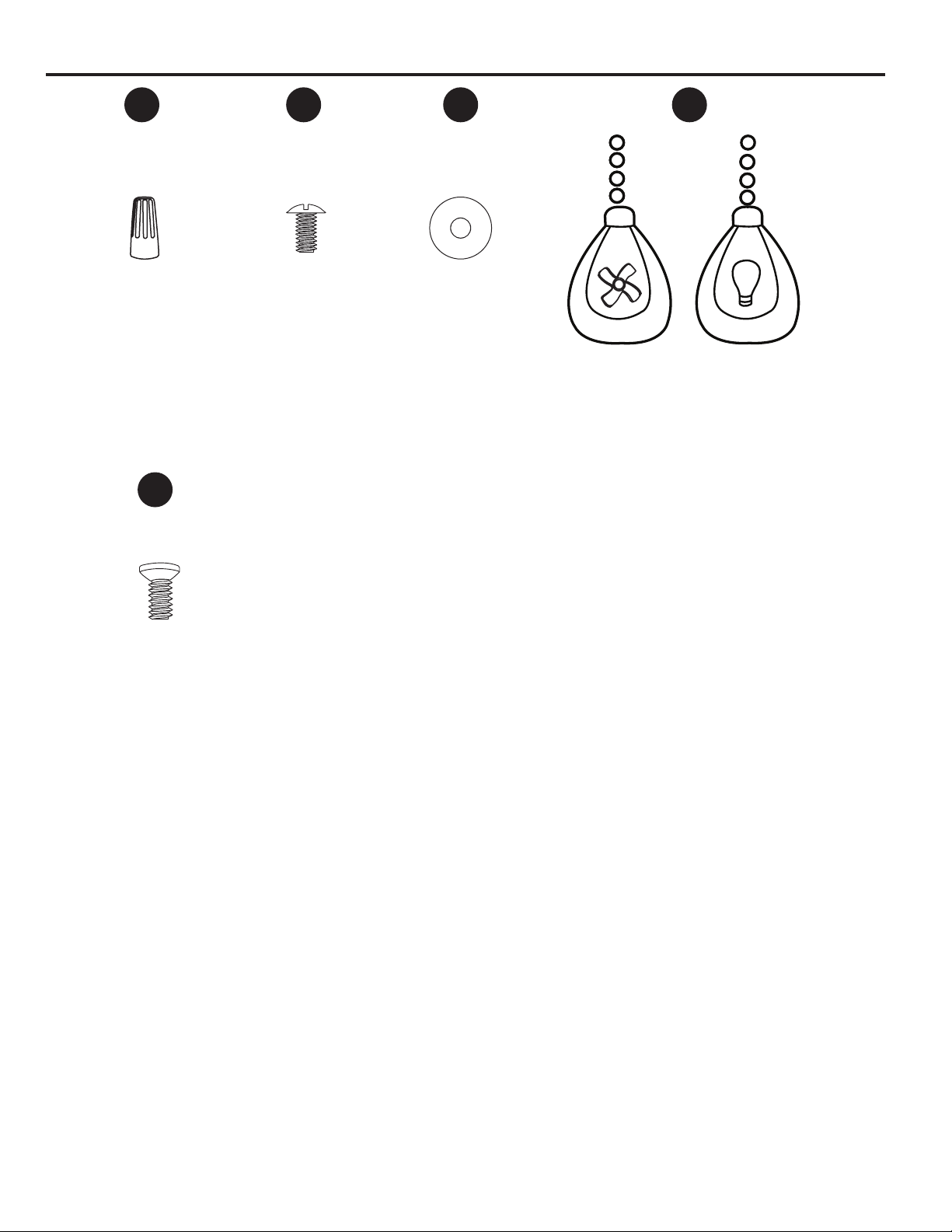
HARDWARE CONTENTS
AA BB CC DD
Wire
Connector
Qty. 3
+ 1 extra
XX
Motor Screw
1 extra
Blade Screw
Qty. 15
+ 1 extra
Blade Washer
Qty. 15
+ 1 extra
H
a
r
b
o
z
e
e
r
B
r
H
e
a
r
b
o
Pull Chain Extension
Qty. 2
e
z
e
e
r
B
r
4

SAFETY INFORMATION
Please read and understand this entire manual before attempting to assemble, operate, or install the product.
• Before you begin installing the fan, disconnect the power by removing fuses or turning off the circuit
breakers.
• Make sure that all electrical connections comply with local codes, ordinances, the National
Electrical Code, and ANSI/NFPA 70-199. Hire a qualied electrician or consult a do-it-yourself
wiring handbook if you are unfamiliar with installing electrical wiring.
• Make sure the installation site you choose allows a minimum clearance of 7 ft. from the blades to
the oor and at least 30 in. from the end of the blades to any obstruction.
• The net weight of this fan is: 14.01 lbs.
DANGER: When using an existing outlet box, make sure the outlet box is securely attached to
the building structure and can support the full weight of the fan. Failure to do this can result in serious
injury or death. The stability of the outlet box is essential in minimizing wobble and noise in the fan
after installation is complete.
WARNING: To avoid personal injury, the use of gloves may be necessary while handling fan
parts with sharp edges.
WARNING: Using a full-range dimmer switch to control fan speed will cause a loud humming
noise from the fan. To reduce the risk of re or electric shock, do NOT use a full-range dimmer switch
to control the fan speed.
WARNING: To reduce the risk of re or electric shock, do NOT use this fan with any solid-state
speed control device.
WARNING: To reduce the risk of re, electric shock, or personal injury, mount the fan to an
outlet box marked “ACCEPTABLE FOR FAN SUPPORT” and use the mounting screws provided with
the outlet box. Most outlet boxes commonly used for the support of lighting xtures are not acceptable
for fan support and may need to be replaced. Consult a qualied electrician if in doubt. Secure the
outlet box directly to the building structure. The outlet box and its support must be able to support the
moving weight of the fan (at least 35 lbs.).
WARNING: To reduce the risk of re, electrical shock, or personal injury, wire connectors
provided with this fan are designed to accept only one 12-gauge house wire and two lead wires from
the fan. If your house wire is larger than 12-gauge or there is more than one house wire to connect to
the two fan lead wires, consult an electrician for the proper size wire connectors to use.
WARNING: To reduce the risk of re, electric shock, or personal injury, do not bend the blade
arms when installing them, balancing the blades, or cleaning the fan. Do not insert objects between
the rotating fan blades.
WARNING: To reduce the risk of personal injury, use only parts provided with this fan. The use
of parts OTHER than those provided with this fan will void the warranty.
5

SAFETY INFORMATION
CAUTION: Read all instructions and safety information before installing your new fan. Review the
accompanying assembly diagrams.
CAUTION: Be sure the outlet box is properly grounded or that a ground (green or bare) wire is present.
CAUTION: Carefully check all screws, bolts and nuts on the fan motor assembly to ensure they are
secured.
PREPARATION
Before beginning the assembly of this product, ensure that all parts are present. Compare all parts
with the package contents list and hardware contents list. If any part is missing or damaged, do not
attempt to assemble the product.
Estimated Assembly Time: 90 minutes
Tools Required for Assembly (not included): Electrical Tape, Phillips Screwdriver, Pliers, Safety
Glasses, Step Ladder and Wire Strippers
Helpful Tools (not included): AC Tester Light, Tape Measure, Wiring Handbook and Wire Cutters
6
 Loading...