

Harbor Breeze 40081, 40082 Installation Manual
Harbor Breeze® is a registered trademark
of LF, LLC. All Rights Reserved.
ITEM #0451798, 0451799
52 IN CLASSIC STYLE
CEILING FAN
MODEL #40081, 40082
Español p. 22
ATTACH YOUR RECEIPT HERE
Serial Number _________________________ Purchase Date _________________________
Questions, problems, missing parts? Before returning to your retailer, call our customer
service department at 1-800-643-0067, 8 a.m. - 6 p.m., EST, Monday - Thursday, 8 a.m. - 5 p.m.,
EST, Friday.
EB13350
LISTED FOR
WET LOCATION
Lowes.com/harborbreeze
1

TABLE OF CONTENTS
Package Contents .................................................................3
Hardware Contents ................................................................4
Safety Information .................................................................5
Preparation ......................................................................6
Initial Installation ..................................................................7
Standard or Angle Mounting Instructions. . . . . . . . . . . . . . . . . . . . . . . . . . . . . . . . . . . . . . . . . . . . . . . . 9
Closemount Instructions ...........................................................12
Final Installation. . . . . . . . . . . . . . . . . . . . . . . . . . . . . . . . . . . . . . . . . . . . . . . . . . . . . . . . . . . . . . . . . . 15
Operating Instructions .............................................................17
Care and Maintenance ............................................................18
Troubleshooting ..................................................................18
Limited Lifetime Warranty ..........................................................20
Replacement Parts List ............................................................21
2
Lowes.com/harborbreeze
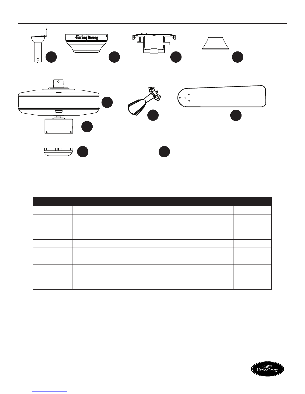
PACKAGE CONTENTS
A
G
B
C D
E
H
I
F
J
PART DESCRIPTION QUANTITY
A Downrod 1
B Canopy (preassembled to Mounting Bracket (C)) 1
C Mounting Bracket 1
D Yoke Cover 1
E Motor Assembly 1
F Switch Housing (preassembled to Motor Assembly (E)) 1
G Switch Housing Cap (preassembled to Switch Housing (F)) 1
H Blade Arm 5
I Blade 5
J Canopy Cover (preassembled to Canopy (B)) 1
3
Lowes.com/harborbreeze
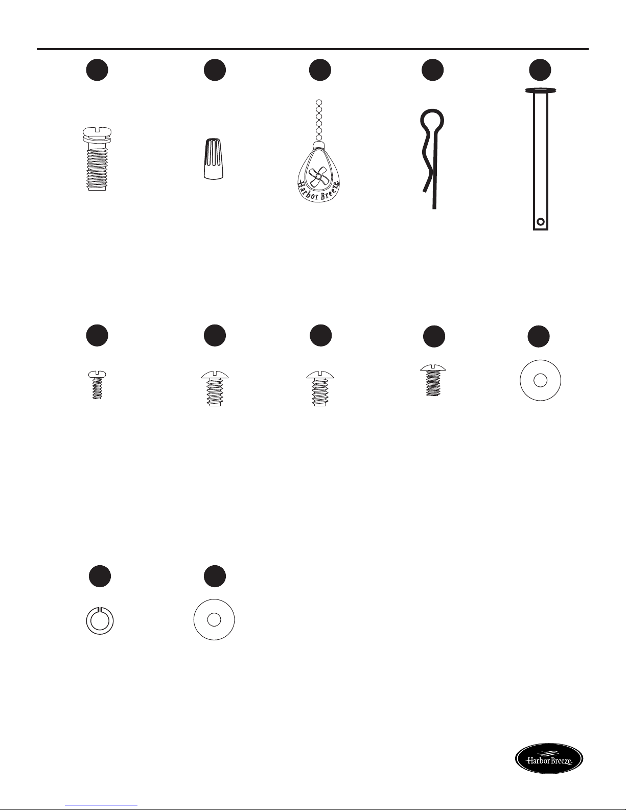
HARDWARE CONTENTS
AA
Motor Screw
Qty. 10
(preassembled to
Motor Assembly (E))
+ 1 extra
FF HH
BB
Wire
Connector
Qty. 3 + 1 extra
GG
CC DD
Pull Chain
Downrod Clip
Extension
Qty. 1
(preassembled to
Downrod (A))
Downrod Pin
Qty. 1
(preassembled to
Downrod (A))
II JJ
EE
Qty. 1
Motor Housing Set
Screw
Qty. 2
(preassembled to
Motor
Assembly (E))
KK
Spring Washer
Qty. 10
(preassembled to
Motor Screw (AA))
+1 extra
Closemount
Screw
Qty. 3
(preassembled to
Motor
Assembly (E))
LL
Rubber Washer
Qty. 5 + 1 extra
Mounting Bracket
Screw
Qty. 4
(preassembled to
Mounting Bracket
(C))
Blade Screw
Qty. 5 + 1 extra
Blade Washer
Qty. 5 + 1 extra
4
Lowes.com/harborbreeze
SAFETY INFORMATION
Please read and understand this entire manual before attempting to assemble, operate or install the product.
• Before you begin installing the fan, disconnect the power by removing fuses or turning off the circuit
breakers.
• Make sure that all electrical connections comply with local codes, ordinances, the National
ElectricalCode,andANSI/NFPA70-199.Hireaqualiedelectricianorconsultado-it-yourself
wiring handbook if you are unfamiliar with installing electrical wiring.
• Make sure the installation site you choose allows a minimum clearance of 7 ft. from the blades to
theoorandatleast30in.fromtheendofthebladestoanyobstruction.
• The net weight of this fan is: 12.32 lbs.
DANGER: When using an existing outlet box, make sure the outlet box is securely attached to
the building structure and can support the full weight of the fan. Failure to do this can result in serious
injury or death. The stability of the outlet box is essential in minimizing wobble and noise in the fan
after installation is complete.
DANGER: If using the fan in a wet location, the fan must be connected to a supply circuit that is
protected by a Ground Fault Circuit Interrupter (GFCI) to reduce the risk of personal injury, electrical
shock or death.
WARNING: To avoid personal injury, the use of gloves may be necessary while handling fan
parts with sharp edges.
WARNING: Toreducetheriskofre,electricshockorpersonalinjury,mountthefantoan
outlet box marked “ACCEPTABLE FOR FAN SUPPORT” and use the mounting screws provided with
theoutletbox.Mostoutletboxescommonlyusedforthesupportoflightingxturesarenotacceptable
forfansupportandmayneedtobereplaced.Consultaqualiedelectricianifindoubt.Securethe
outlet box directly to the building structure. The outlet box and its support must be able to support the
moving weight of the fan (at least 35 lbs.). Do NOT use a plastic outlet box.
WARNING: Toreducetheriskofre,electricalshock,orpersonalinjury,wireconnectors
provided with this fan are designed to accept only one 12-gauge house wire and two lead wires from
the fan. If your house wire is larger than 12 gauges or there is more than one house wire to connect
to the two fan lead wires, consult an electrician for the proper size wire connectors to use.
WARNING: Toreducetheriskofreorelectricshock,donotusethefanwithanysolid-state
speed-control device or control the fan speed with a full-range dimmer switch.
WARNING: Toreducetheriskofre,electricshock,orpersonalinjury,donotbendtheblade
arms when installing them, balancing the blades, or cleaning the fan. Do not insert objects between
the rotating fan blades.
WARNING: To reduce the risk of personal injury, use only parts provided with this fan. The use
of parts OTHER than those provided with this fan will void the warranty.
5
Lowes.com/harborbreeze

SAFETY INFORMATION
CAUTION: Read all instructions and safety information before installing your new fan. Review the
accompanying assembly diagrams.
CAUTION: Be sure the outlet box is properly grounded or that a ground (green or bare) wire is present.
CAUTION: Carefully check all screws, bolts, and nuts on the fan motor assembly to ensure they are
secured.
PREPARATION
Before beginning the assembly of this product, ensure all parts are present. Compare all parts with
the package contents list and hardware contents list. If any part is missing or damaged, do not
attempt to assemble the product.
After opening the top of the carton, remove the mounting hardware package from the foam inserts,
then remove the motor from the packaging and place it on a soft surface, such as a carpet, to avoid
damagetothenish.
Estimated Assembly Time: 120 minutes
Tools Required for Assembly (not included): Electrical Tape, Phillips Screwdriver, Pliers, Safety
Glasses, Step Ladder, and Wire Strippers
Helpful Tools (not included): AC Tester Light, Tape Measure, Wiring Handbook and Wire Cutters
6
Lowes.com/harborbreeze
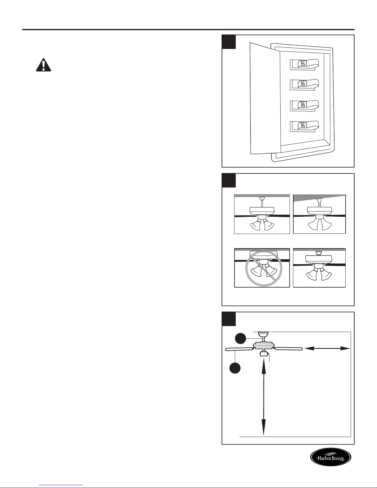
INITIAL INSTALLATION
1. Turn off the circuit breakers and the wall switch to the
fan supply line leads.
DANGER: Failure to disconnect the power
supply prior to installation may result in serious injury
or death.
2. Determine the mounting method to use.
Helpful Hint: Downrod mounting is best suited for
ceilings 8 ft. or higher. For taller ceilings you may
want to use a longer downrod (not included). Angle
mounting is best suited for angled or vaulted ceilings.
A longer downrod is sometimes necessary to ensure
proper blade clearance.
Note: Flushmount installation is not available for this
item.
1
2
Downrod Mounting
Angle Mounting
Important: If using the angle mount, check to ensure
the ceiling angle is not steeper than 23°.
3. Ensure the blades (I) will be at least 30 in. from any
obstructions. Also check the downrod (A) length to
ensure the blades (I) will be at least 7 ft. above the
oor.
3
Flushmount Closemount
A
I
7 ft.
minimum
30 in.
minimum
7
Lowes.com/harborbreeze

C
INITIAL INSTALLATION
4. Remove the two mounting bracket screws (HH)
from the round holes of the canopy (B). Set aside
for later use. Detach mounting bracket (C) from
canopy (B).
Hardware Used
HH
Mounting
Bracket Screw
x 2
5. Feed black, blue and white wires up from the plug on
the mounting bracket (C) up through the hole in the
top.
4
C
HH
B
5
6. Remove and discard the three rubber stoppers and
theveplasticspacersfromtheundersideofthe
motor assembly (E).
For Standard or Angle Mounting Instructions,
continue to page 9. For Closemount Instructions,
proceed to page 12.
6
Rubber
Stopper
Plastic
Spacer
E
8
Lowes.com/harborbreeze
STANDARD OR ANGLE MOUNTING INSTRUCTIONS
WARNING:Toreducetheriskofre,electricalshock,orpersonalinjury,wireconnectors
provided with this fan are designed to accept only one 12-gauge house wire and two lead wires from
the fan. If your house wire is larger than 12 gauges and there is more than one house wire to connect
to the two fan lead wires, consult an electrician for the proper size wire connectors to use.
CAUTION: Be sure the outlet box (not included) is properly grounded or that a ground (green or bare) wire
is present.
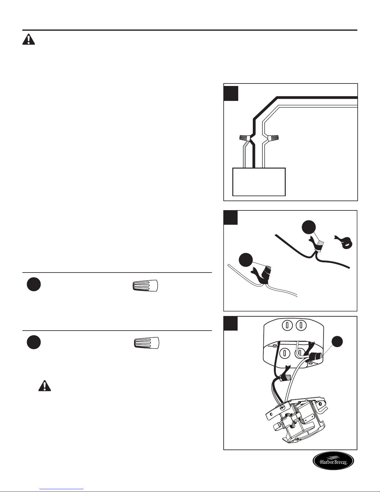
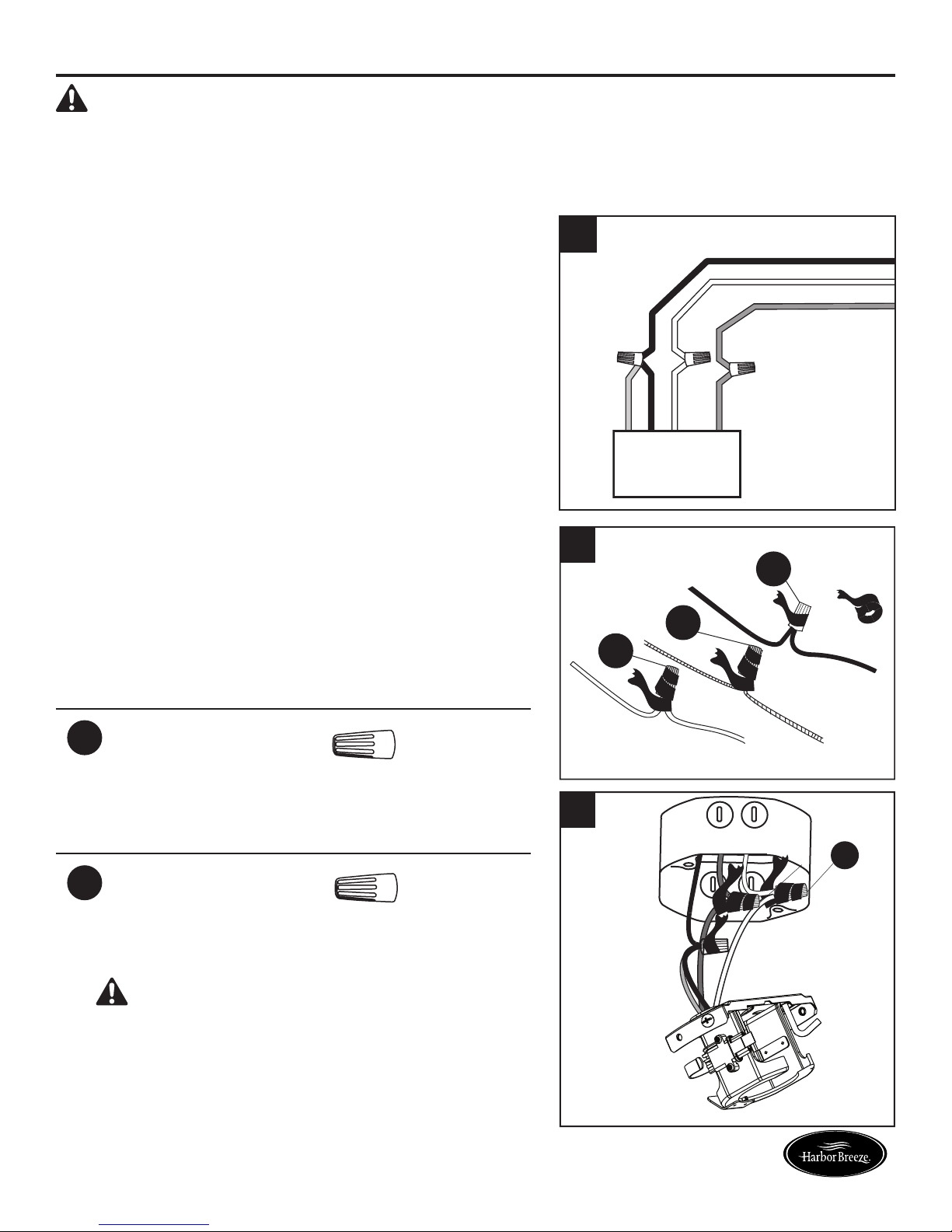
1. Connect with supply and mounting bracket (C) wires
according to the diagram and these steps:
1
Black
White
•ConnecttheWhitewirefromthemountingbracket
(C) to the White supply wire.
•ConnecttheBlueandBlackwirefromthemounting
bracket (C) to the Black supply wire.
•Secureallwiringconnectionstogetherwithwire
connectors (BB).
Note: The Black wire is hot power for the fan. The
White wire is common. The Blue wire is
hot power for light (sold separately; wiring
instructions will differ if optional light kit is
purchased. Refer to light kit manufacturer’s
instructions). The Green wire is the ground
wire and will be connected later. If house wires
are different colors than referred to above, stop
immediately. It is recommended a professional
electrician determines the proper wiring.
Hardware Used
BB
Wire Connector x 2
2. Wrap electrical tape (not included) around each
individual wire connector (BB) down to the wire.
Hardware Used
2
3
Blue
Mounting
Bracket
BB
Black
White
BB
BB
Wire Connector x 2
3. Turn the spliced/taped wires upward and gently push
the wires and wire connectors (BB) into the outlet box.
WARNING: Ensure no bare wire or wire strands
are visible after making connections. Place the Black
and White wire connections on opposite sides of the
outlet box.
BB
A
9
Lowes.com/harborbreeze
STANDARD OR ANGLE MOUNTING INSTRUCTIONS
E
A
DD
EE
FF
A
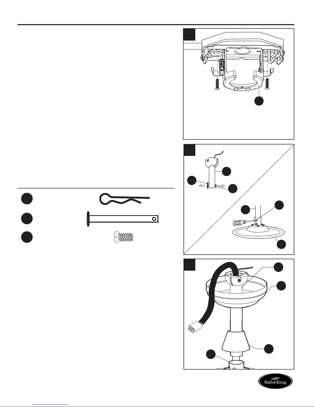
4. Feed green/bare (ground) supply wire down through
the hole in the top of the mounting bracket (C). Secure
the mounting bracket (C) to the outlet box using
screws and washers provided with the outlet box.
5. Remove the downrod clip (DD) and downrod pin
(EE) from the downrod (A). Then partially loosen the
motor housing set screws (FF) in the yoke at the top
of the motor assembly (E).
4
C
5
Hardware Used
DD
EE
FF
Downrod Clip x 1
Downrod Pin x 1
Motor Housing
Set Screw
6. Place the downrod (A) into the canopy (B) and yoke
cover (D). Feed the wire harness from the motor
assembly (E) through the downrod (A).
x 2
6
12
A
B
D
E
10
Lowes.com/harborbreeze
STANDARD OR ANGLE MOUNTING INSTRUCTIONS
C
A
C
A
Tab
Slot
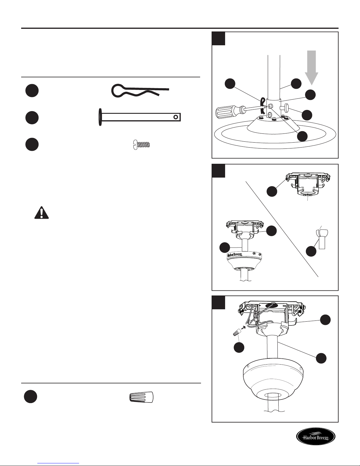
7. Slide the downrod (A) into the yoke of the motor
assembly (E), align the holes, and re-install the
downrod clip (DD) and downrod pin (EE). Then
tighten the motor housing set screws (FF).
Hardware Used
DD
EE
FF
Downrod Clip x 1
Downrod Pin x 1
Motor Housing
Set Screw
8. Carefully lift the downrod (A) onto the mounting
bracket (C). Rotate the downrod (A) until the slot on
the downrod (A) engages the tab on the mounting
bracket (C).
x 2
7
8
DD
A
E
EE
FF
DANGER: Failure to align the slot in the ball
with the tab may result in serious injury or death.
9. Connect the green wires from the downrod (A) and
the mounting bracket (C) to the bare/green (ground)
supply wire using a wire connector (BB).
Then, wrap electrical tape around the wire connector
(BB) down to the wire. Turn the spliced/taped wires
upward and gently push the wires and wire connector
(BB) into the outlet box.
Proceed to Final Installation on page 15.
Hardware Used
9
C
BB
A
BB
Wire Connector x 1
11
Lowes.com/harborbreeze
CLOSEMOUNT INSTRUCTION
WARNING:Toreducetheriskofre,electricalshock,orpersonalinjury,wireconnectors
provided with this fan are designed to accept only one 12-gauge house wire and two lead wires from
the fan. If your house wire is larger than 12 gauges and there is more than one house wire to connect
to the two fan lead wires, consult an electrician for the proper size wire connectors to use.
CAUTION: Be sure the outlet box (not included) is properly grounded or that a ground (green or bare) wire
is present.
1. Connect with supply and mounting bracket (C) wires
1
Black
according to the diagram and these steps:
•Connectthegreenwirefromthemountingbracket
(C) to the Bare/Green (ground) supply wire.
White
Bare/Green
•ConnecttheWhitewirefromthemountingbracket
(C) to the White supply wire.
•ConnecttheBlueandBlackwirefromthemounting
bracket (C) to the Black supply wire.
Blue
White
Green
Black
•Secureallwiringconnectionstogetherwithwire
connectors (BB).
Mounting Bracket
Note: The Black wire is hot power for the fan. The
White wire is common. The Blue wire is hot power
for light (sold separately; wiring instructions will
differ if optional light kit is purchased. Refer to light
kit manufacturer’s instructions). The Green wire
2
BB
is the ground. If house wires are different colors
than referred to above, stop immediately. It is
recommended a professional electrician determines
BB
BB
the proper wiring.
Hardware Used
BB
Wire Connector x 3
2. Wrap electrical tape (not included) around each
individual wire connector (BB) down to the wire.
Hardware Used
BB
Wire Connector x 3
3. Turn the spliced/taped wires upward and gently push
the wires and wire connectors (BB) into the outlet box.
WARNING: Ensure no bare wire or wire strands
are visible after making connections. Place the Black
and White wire connections on opposite sides of the
outlet box.
12
3
BB
A
Lowes.com/harborbreeze
CLOSEMOUNT INSTRUCTIONS
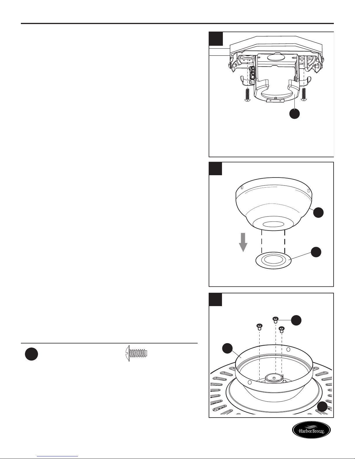
4. Secure the mounting bracket (C) to the outlet box
using screws and washers provided with the outlet
box.
5. Remove the canopy cover (J) from the bottom of the
canopy (B).
4
1
5
C
Helpful Hint: Closemount-style mounting is more
suitable for ceilings lower than 8 ft. high. The
downrod (A) and canopy cover (J) are not used in
this type of installation.
6. Remove closemount screws (GG) from the top of the
motor assembly (E). Align the canopy (B) with the
holes in the top of the motor assembly (E). Secure
the canopy (B) to the top of the motor assembly (E)
with the closemount screws (GG).
Hardware Used
GG
Closemount
Screw
x 3
B
J
6
GG
B
13
E
Lowes.com/harborbreeze
 Loading...