

Harbor Breeze 35086 Installation Manual
ITEM #0552025
CEILING FAN
MODEL #35086
Français p. 14
ATTACH YOUR RECEIPT HERE
Serial Number
Questions, problems, missing parts? Before returning to your retailer, call our
customer service department at 1-800-643-0067, 8 a.m. - 6 p.m., EST, Monday - Thursday,
8 a.m. - 5 p.m., EST, Friday.
Purchase Date
1
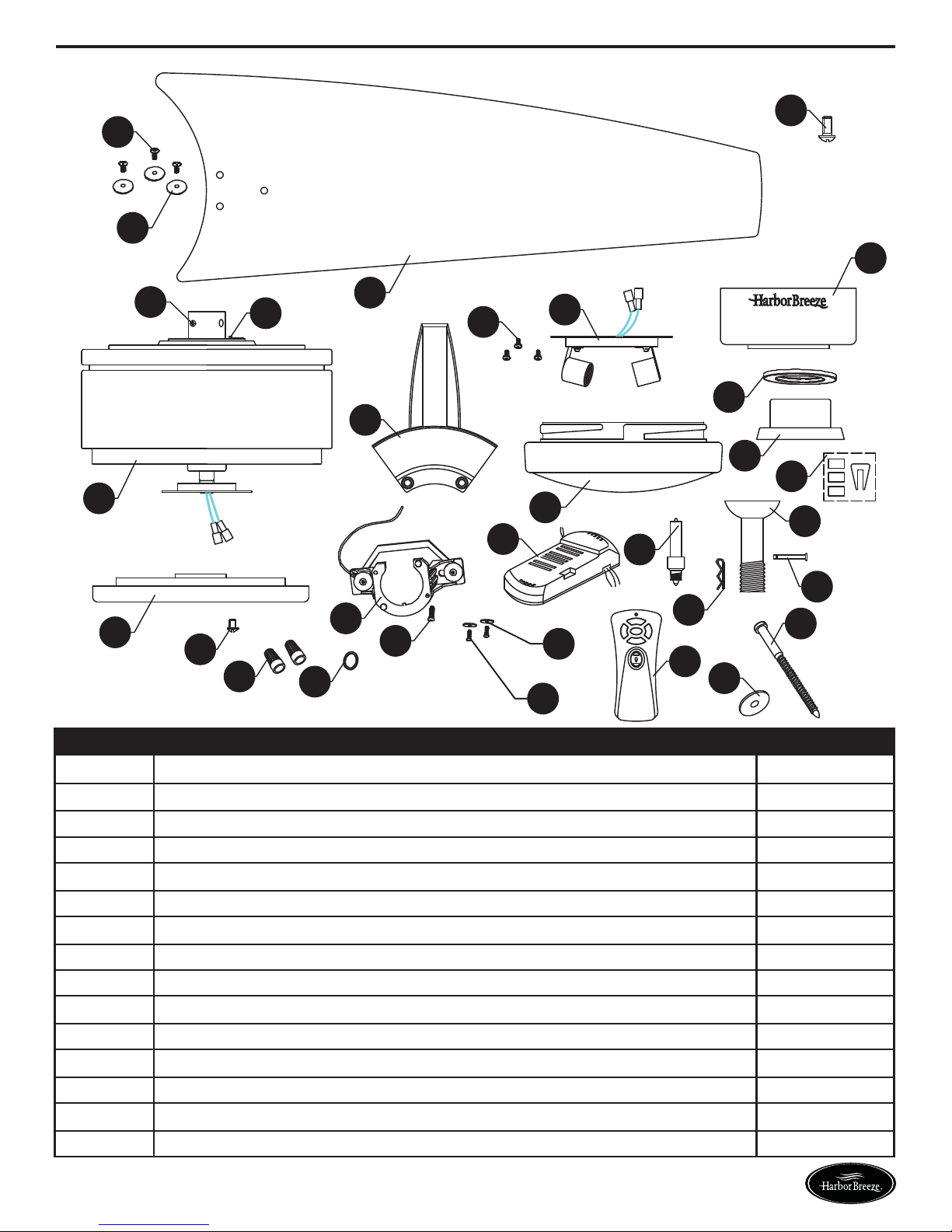
PACKAGE CONTENTS
M
L
EE
G
T
S
K
X
Y
H
I
O
N
J
V
D
Q
W
F
E
CC
R
DD
P
A
Z
AA
BB
U
B
C
PART DESCRIPTION QUANTITY
A
B
C
D
E
F
G
H
I
J
K
L
M
N
O
Hanging Bracket 1
Washer 2
Mounting Screw 2
Down Rod 1
Hair Pin 1
Clevis Pin 1
Canopy 1
Canopy Hole Cover 1
Blade Bracket 5
Motor Assembly 1
Fan Blade 5
Blade Washer 15
Blade Screw 15
Blade Balancing Kit 1
Motor Coupling Cover 1
2
Lowes.com/harborbreeze
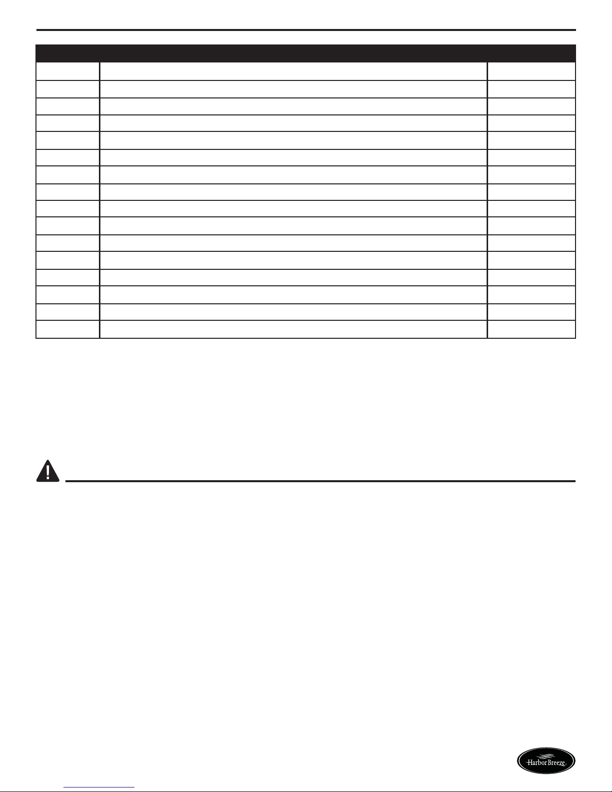
PACKAGE CONTENTS
PART DESCRIPTION QUANTITY
P
Q
R
S
T
Glass Mounting Ring 1
Receiver 1
Remote 1
Reverse Switch 1
Set Screw 2
U
V
W
X
Y
Z
AA
BB
CC
DD
EE
Shoulder Screw 2
Glass Shade 1
50 Watt E11 Bulb 2
Light Assembly Screw 3
Light Assembly 1
Glass Mounting Ring Screw 3
Wire Connector 6
Spring Washer 1
Lag Screw 1
Lag Washer 1
Blade Bracket Screw 10
SAFETY INFORMATION
Please read and understand this entire manual before attempting to assemble, operate or install the
product.
WARNING:
• Important: When using an existing outlet box, be sure the box is securely attached to the building
structure and can support the full weight of the fan. Failure to do so can result in serious injury or
death.
• Turn off circuit breakers and wall switch to the fan supply wire leads. Warning: Failure to
disconnect power supply prior to installation may result in serious injury or death.
• Do not install fan on a ceiling with a pitch greater than 20°.
• Installation work and electrical wiring must be done by qualified person(s) in accordance with all
applicable codes and standards (ANSI/NFPA 70-1999). If you are unfamiliar with the wiring
codes, contact a qualified electrician.
• Important: Be sure wiring box is properly grounded or that a ground (green) wire is present.
• Make sure the installation site you choose allows a minimum of 7 feet from the floor to the end of
the blades
3
Lowes.com/harborbreeze
PREPARATION
Before beginning assembly of product, make sure all parts are present. Compare parts with package
contents list and diagram. If any part is missing or damaged, do not attempt to assemble the product.
Contact customer service for replacement parts.
Estimated assembly time: 30 minutes to 1 hour.
Tools Required for Assembly (not included): Phillips screwdriver, flathead screwdriver, wire strippers,
electrical tape, ladder, safety glasses, silicone caulk, caulking gun.
ASSEMBLY INSTRUCTIONS
• WARNING-To reduce risk of fire, electric shock, or personal injury, mount to outlet box marked
“Acceptable for Fan Support of 15.9kg (35lbs) or less” and use mounting screws provided with the
outlet box and/or support directly from building structure. Most outlet boxes commonly used for
the support of luminaries are not acceptable for fan support and may need to be replaced.
Consult a qualified electrician if in doubt.
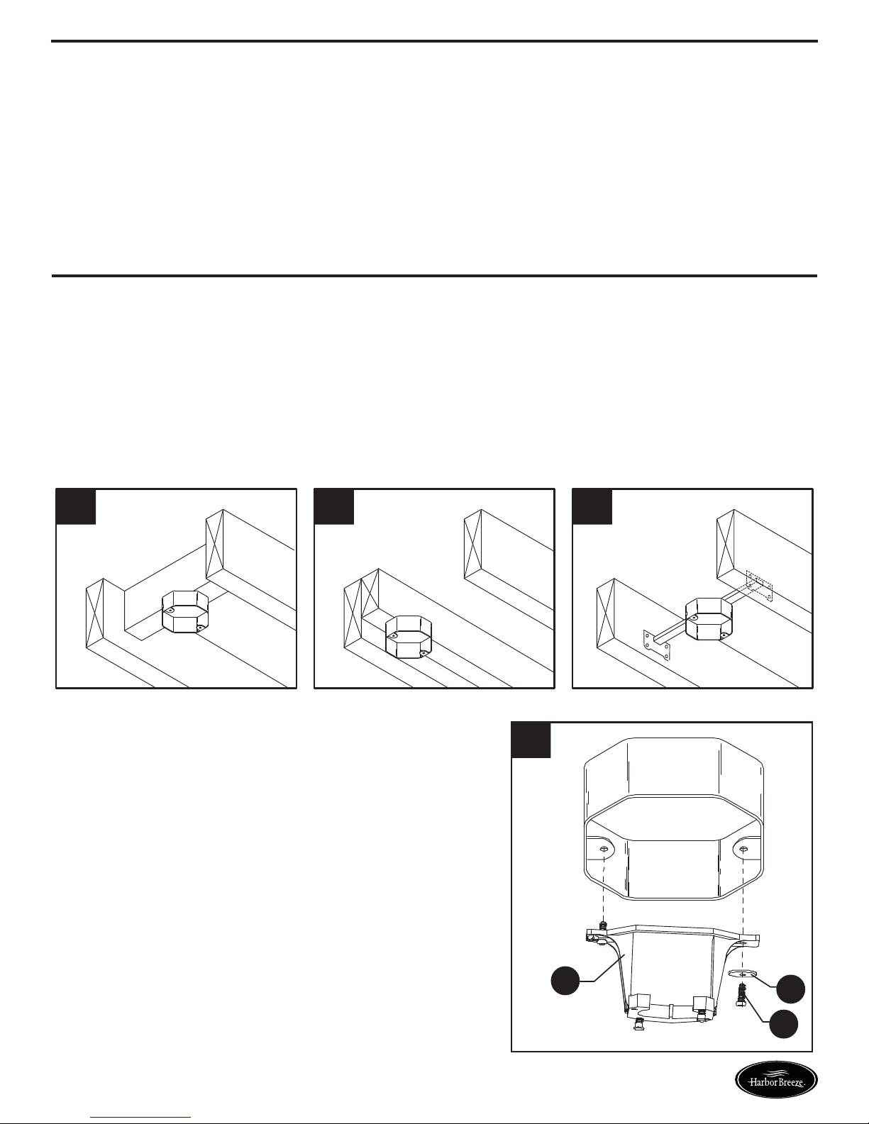
• Warning-Risk of fire, electric shock, or personal injury. Ceiling fans may be either directly
supported from a structural framing member of a building and (see examples in figures A & B) or
may be mounted to an outlet box marked acceptable for fan support of 31.8 kg (70 lbs) to 15.9kg
(35 lbs) (see example in figure C).
A B C
1. Secure the hanger bracket (A) to the ceiling outlet
box using mounting screws (C) and washers (B)
provided with the outlet box. Important: If attaching
the fan to a sloped ceiling, make sure open end of
mounting bracket is installed facing the roof. Do not
install fan on a ceiling with a pitch greater than 20°.
1
A
B
C
4
Lowes.com/harborbreeze
ASSEMBLY INSTRUCTIONS
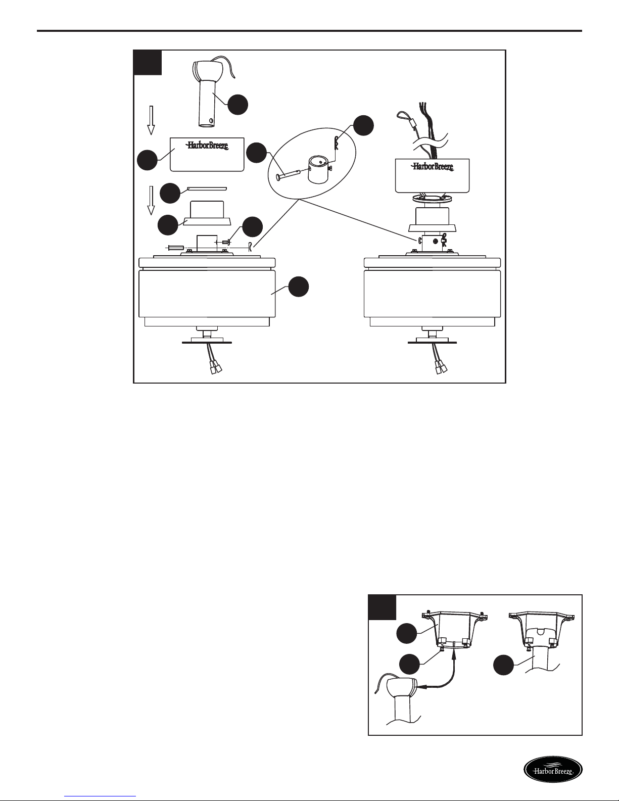
2
D
E
G
F
H
O
T
J
2. Remove the hairpin (E) clip and clevis pin (F) from the downrod support of the motor assembly (J)
and loosen the two set screws (T). Slide the downrod (D) through the canopy (G), canopy hole
cover (H) and motor coupling cover (O). Feed the black, white and blue wires with safety cable
from fan through the downrod (D). Insert the downrod into motor assembly (J) Secure clevis pin
(F) with hairpin (E) clip and tighten setscrews (T).
3. Loosen the two shoulder screws (U) without fully
removing in the hanger bracket (A). Carefully lift the
fan and seat the downrod (D)/hanger ball assembly
on the hanger bracket (A) that was just attached to
the outlet box. Be sure the groove in the ball is lined
up with the tab on the hanger bracket (A).
3
A
U
5
Lowes.com/harborbreeze
D
ASSEMBLY INSTRUCTIONS
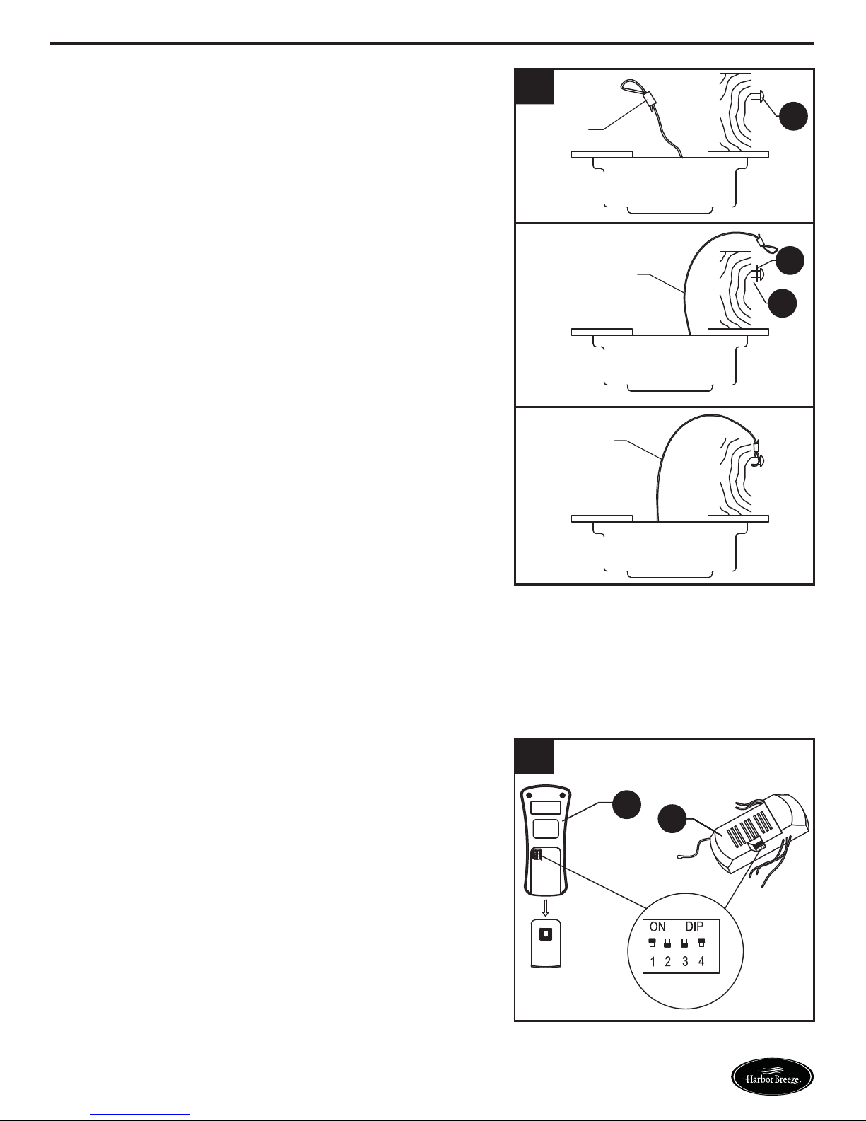
4. For Canadian installation and for USA fans over 35
lbs, the safety cable must be installed into the house
structure beams using a 3” lag screw (CC). Make
sure that when the safety cable is fully extended the
lead wires are longer than the cable and no stress is
placed on the lead.
4
Safety
Cable
Safety
Cable
Safety
Cable
CC
DD
BB
5. The frequency switches on your receiver and
transmitter have been preset at the factory. Remove
the transmitter battery cover and make sure the
switches are set to the same position. This must be
done so that your fan will communicate properly. If
you are using more than one fan in the same area
and want to control them separately, change one
fan’s dip switch settings in the transmitter and
remote to a new pattern.
NOTE: If not using for long periods of time, remove
battery to prevent damage to transmitter. Store the
remote away from excessive heat or humidly.
5
R
6
Q
Lowes.com/harborbreeze
ASSEMBLY INSTRUCTIONS
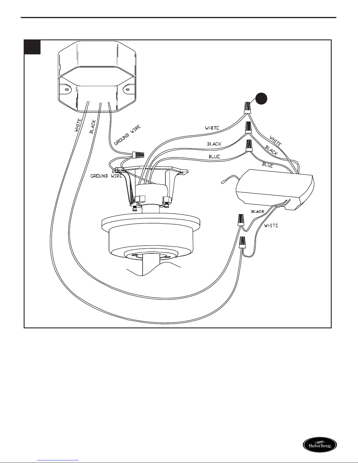
6
AA
6. Wiring the fan per wiring diagram and Securely connect wires with wire connectors (AA):
• Connect WHITE fan motor wire to WHITE receiver unit wire marked TO MOTOR N.
• Connect BLUE fan motor wire to BLUE receiver unit wire marked FOR LIGHT.
• Connect BLACK fan motor wire to BLACK receiver unit wire marked TO MOTOR L.
• Connect BLACK supply wire to BLACK receiver unit wire marked AC IN L.
• Connect WHITE supply wire to WHITE receiver unit wire marked AC IN N.
• Connect GROUND (GREEN) wires from hanger bracket and downrod ball, to GROUND (GREEN
or BARE COPPER) from house.
7
Lowes.com/harborbreeze
ASSEMBLY INSTRUCTIONS
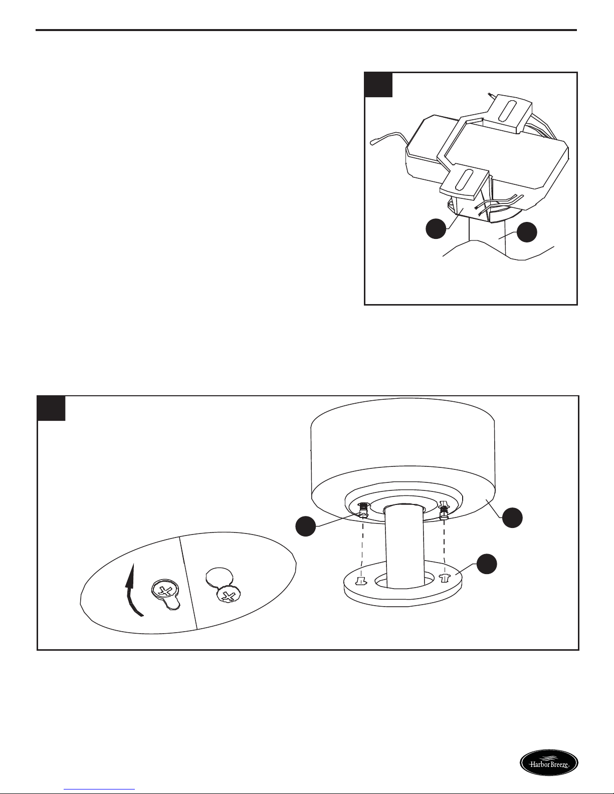
7. Once wiring step has been completed, slide the
wired remote receiver in between the bracket (A)
and the top of the downrod ball (D) with the flat side
of the receiver facing the ceiling. Turn lead wires
upward and carefully push them into the outlet box,
with the white and green wires to one side of the box
and the black wire toward the other side.
7
8
U
A
D
G
8. Loosen the two shoulder screws (U) without fully removing the hanger bracket (A). Assemble
canopy (G) by rotating keyhole slot in canopy over shoulder screws (U) in hanger bracket (A).
Tighten shoulder screws (U). Securely attach and tighten the canopy hole cover (H) over the
shoulder screws (U) in the hanger bracket (A) utilizing the keyhole slot twist-lock feature.
H
8
Lowes.com/harborbreeze
 Loading...