

Harbor Breeze 1179 Package Contents Manual
PREPARATION
SAFETY INFORMATION
HARDWARE CONTENTS
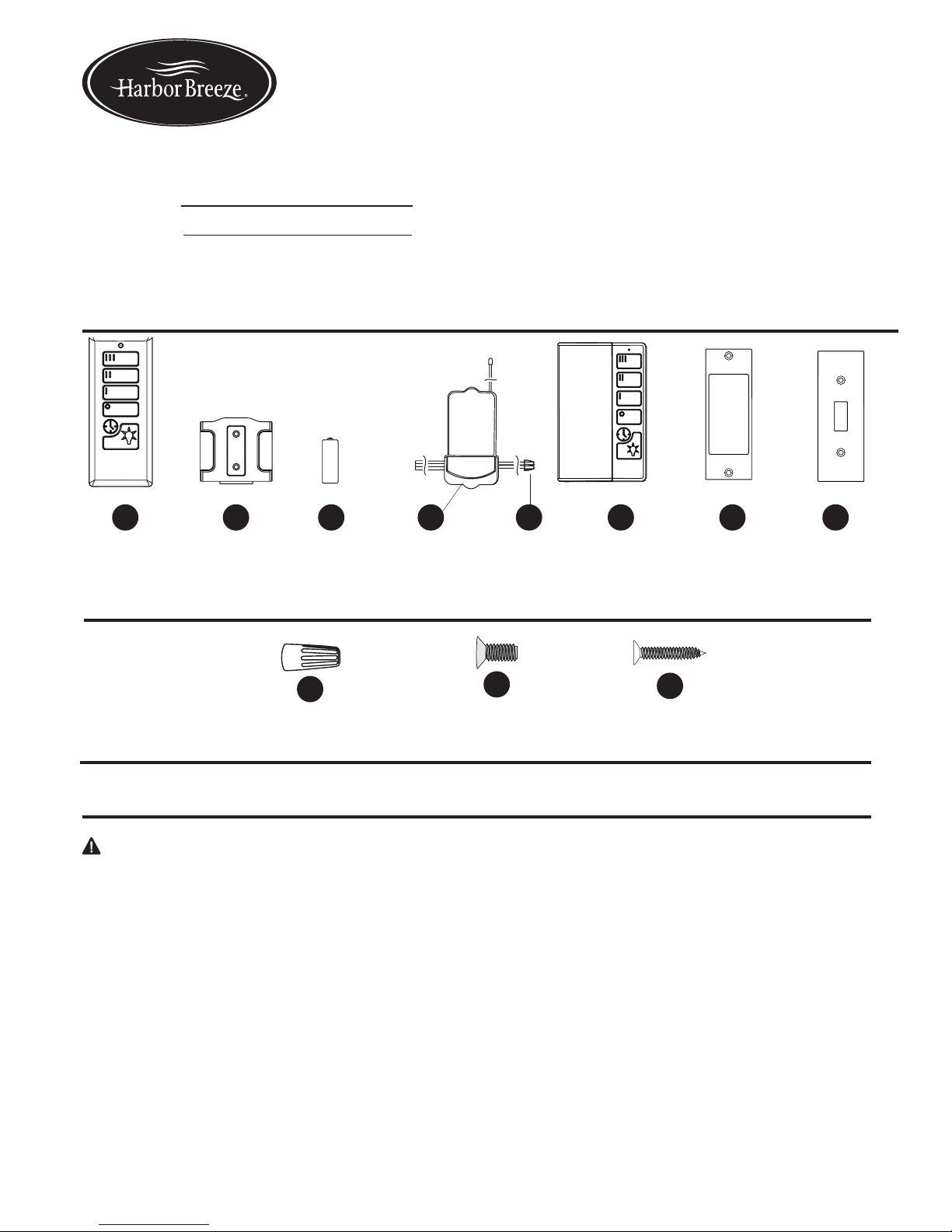
PACKAGE CONTENTS
WALL CONTROL AND REMOTE
ITEM #0745365
MODEL #41179
Serial Number
Purchase Date
ATTACH YOUR RECEIPT HERE
Harbor Breeze® is a registered trademark
of LF, LLC. All rights reserved.
Remote
Qty. 1
Wall Bracket
Qty. 1
Battery
Qty. 2
Receiver
Qty. 1
Push-on
Connector
Qty. 2
Wall Control
Qty. 1
Decor
Plate
Qty. 1
Standard
Plate
Qty. 1
Wire Connector
Qty. 3
Plate Screw
Qty. 2
A B C D E F G
AA
BB
H
Read instructions completely before installing the remote.
WARNING: If the color of the household supply wires is different than what is referred to in the instructions below, a
professional electrician should determine proper wiring.
CAUTION:
• Do not install in damp locations. For indoor use only.
• Do not use with fans that have integrated remote controls.
• Be sure the outlet box is properly grounded or that a green or bare (ground) wire is present.
• This unit is intended to control a ceiling fan with electrical source of AC 110/120V, 60Hz.
• To reduce the risk of fire or electric shock, do NOT use a full-range dimmer switch to control the fan speed.
• This equipment has been tested and found to comply with the limits for a Class B digital device, pursuant to Part 15 of
the FCC Rules. These limits are designed to provide reasonable protection against harmful interference in a residential
installation. This equipment generates, uses and can radiate radio frequency energy and, if not installed and used in
accordance with the instructions, may cause harmful interference to radio communications.
However, there is no guarantee that interference will not occur in a particular installation. If this equipment does cause
harmful interference to radio or television reception, which can be determined by turning the equipment off and on, the
user is encouraged to try to correct the interference by one or more of the following measures: Reorient or relocate the
receiving antenna. --Increase the separation between the equipment and receiver. --Connect the equipment into an
outlet on a circuit different from that to which the receiver is connected. --Consult the dealer or an experienced radio/
TV technician for help. Any changes or modications not expressly approved by the grantee of this device could void the
user’s authority to operate the equipment. FCC ID: KUJCE 10409, KUJCE 10003
Questions? Call our customer service department
at 1-800-643-0067, 8 a.m. - 6 p.m., EST, Monday Thursday, 8 a.m. - 5 p.m., EST, Friday.
Mounting Screw
Qty. 2
CC
Tools required for assembly (not encluded): Electrical Tape and Phillips Screwdriver
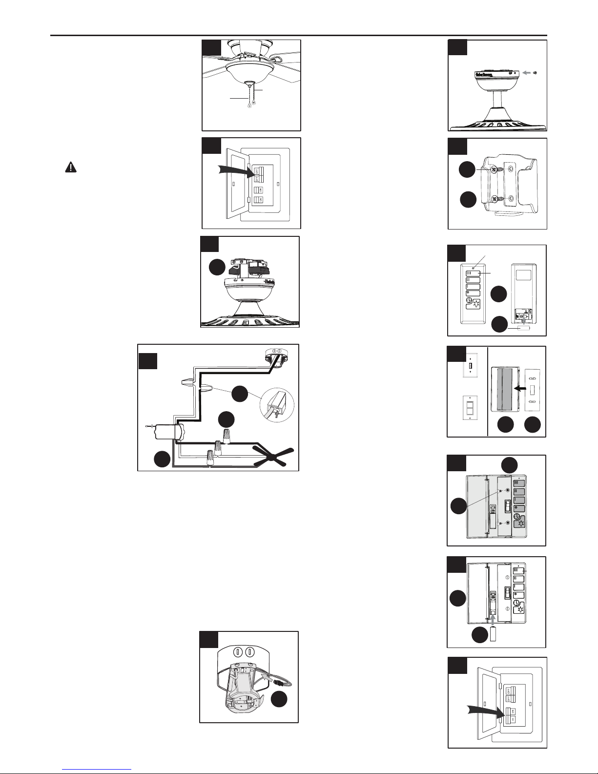
ASSEMBLY INSTRUCTIONS
5. Wrap electrical tape (not
included) around each wire
connector (AA) down to
the wire. Then, push wire
connections into the outlet
box. Place the White wire
connections on the opposite
side of the outlet box from
the Black and Blue wire
connections.
8
9
5
6
7
12
10
11
High
LED Indicator
AA
CC
B
F
H
F
BB
C
F
A
C
High
OFF
Standard
Style
Decor
Style
Back
H
a
r
b
o
r
B
r
e
e
z
e
H
a
r
b
o
r
B
r
e
e
z
e
1. Use existing pull chains on the
desired fan to set fan speed to
high and to turn the light on.
2. Turn off circuit breakers and wall
switch to the fan.
DANGER: Failure to
disconnect power supply prior to
installation may result in serious
injury or death.
3. Lower the canopy of the
previously assembled fan and
insert receiver (D). Note: If
installing this product with a new
fan, insert the receiver (D) in the
mounting bracket before wiring
the fan; wire the fan according to
these instructions, then continue
fan assembly as directed in the
fan’s instruction manual.
2
1
3
4. Disconnect
existing wire
connections, then
secure all wire
connections with
wire connectors
(AA) and push-on
connectors (E)
according to
diagram and
these steps:
Fan Pull
Chain
Light Pull
Chain
Black (hot/power)
White (neutral)
White
White
White
Black
Black
Blue
Blue
Black
Antenna
4
• Connect the Blue wire with white label from the receiver
(D) to the Blue fan wire.
• Connect the Black wire with white label from the
receiver (D) to the Black fan wire.
• Connect the White wire with white label from the receiver
(D) to the White fan wire.
• Connect the Black wire with red label from the receiver
(D) to the Black (hot/power) supply wire.
• Connect the White wire with red label from the receiver
(D) to the White (neutral) supply wire.
D
D
AA
E
6. Reinstall the canopy.
7. If desired, the wall bracket
(B) can be attached to a
wall using the mounting
screws (CC). Slide small
plate over mounting
screws, then rest the
remote in the wall bracket
for easy storage.
8. Remove the battery cover
from the back of remote (A)
and install an A23 12-volt
battery (C). Replace the
battery cover and press the
High button to ensure the
LED indicator illuminates
and the fan turns on.
9. Select the adapter plate
that corresponds to the
style of wall switch to which
the wall control (F) will be
mounted -- decor plate (G)
or standard plate (H). Then
snap the plate into the back
of the wall control (F).
10. Remove the two screws
from the wall switch to
which the wall control (F)
will be mounted. With door
to wall control (F) open, use
the two plate screws (BB)
to attach the wall control (F)
to the switch plate.
11. Insert the remaining A23
12-volt battery (C) into the
battery compartment of wall
control (F). Press the High
button to ensure the LED
indicator illuminates and the
fan turns on.
12. Turn on power to wall
control and ceiling fan.
 Loading...