

Harbor Breeze 00966 Installation Manual
ITEM #0451808
IMPACT CEILING FAN
MODEL #00966
UL MODEL #IPT48
Harbor Breeze® is a registered trademark
of LF, LLC. All rights reserved.
Español p. 16
ATTACH YOUR RECEIPT HERE
Serial Number
Purchase Date
Questions, problems, missing parts? Before returning to your retailer, call our customer
service department at 1-800-643-0067, 8 a.m. - 6 p.m., EST, Monday - Thursday, 8 a.m. 5 p.m., EST, Friday.
EB15512
Lowes.com/harborbreeze
1
2
TABLE OF CONTENTS
3
Lowes.com/harborbreeze
Lowes.com/harborbreeze
Safety Information ................................................................................................................3
Package Contents ................................................................................................................4
Hardware Contents ..............................................................................................................5
Preparation........................................................................................................................... 5
Assembly instructions...........................................................................................................6
Operating Instructions ........................................................................................................13
Care and Maintenance .......................................................................................................14
Troubleshooting..................................................................................................................14
Warranty.............................................................................................................................15
Replacement Parts List ......................................................................................................15
SAFETY INFORMATION
READ AND SAVE THESE INSTRUCTIONS
Please read and understand this entire manual before attempting to assemble, operate, or install
the product.
• When using an existing outlet box, be sure the box is securely attached to the building structure
and can support the full weight of the fan, so as to avoid potential serious injury or death.
• All wiring must be in accordance with the National Electrical Code “ANSI/NFPA 70-1999” and
local electrical codes. Electrical installation should be performed by a qualified licensed
electrician.
• DO NOT use bulbs with a wattage greater than the maximum value stated on the fixture and in
this manual. Using a higher wattage bulb than specified will increase fixture temperature and
cause risk of fire.
• Disconnect the electrical supply circuit to the fan before installing light kit.
• Electrical diagrams are for reference only.
• The net weight of this fan including the light kit is: 15.4 lbs.
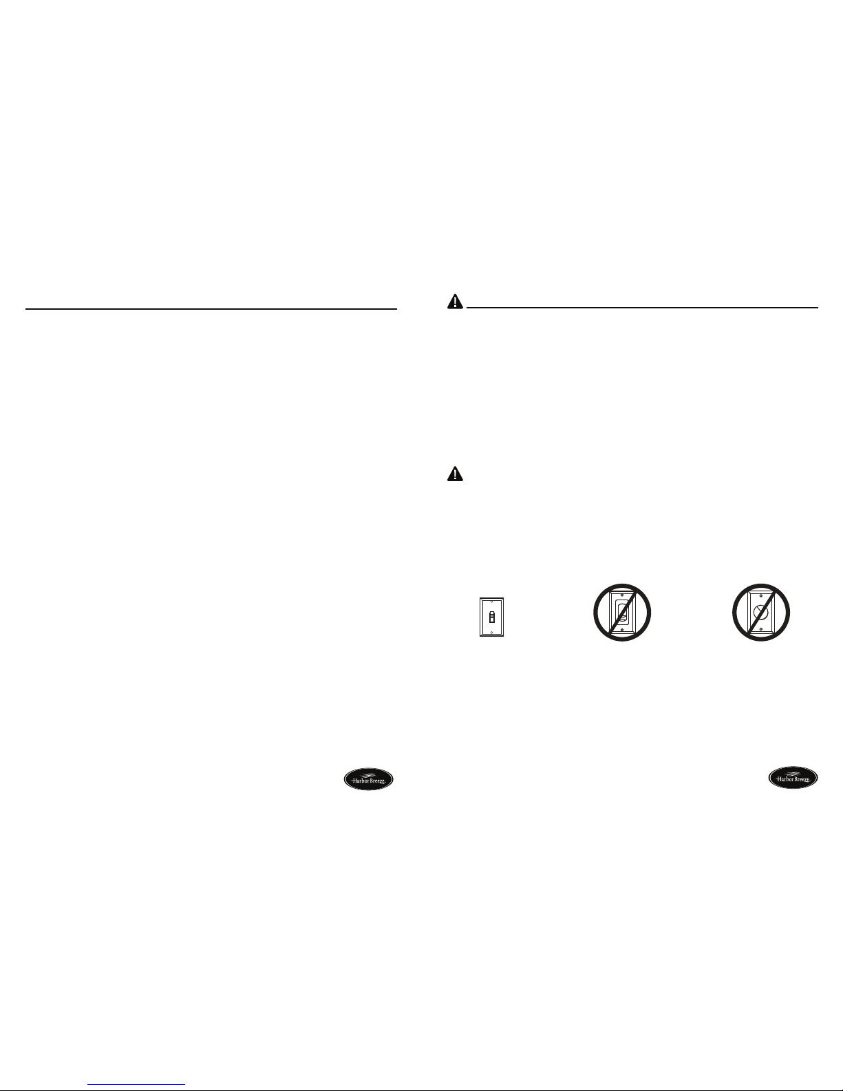
WARNING
ON
ON / OFF switch NO Variable speed wall control NO Dimmer switch
• ELECTRIC SHOCK HAZARD - To reduce the risk of electric shock, do not use this fan with any
solid-state speed control device.
• ELECTRIC SHOCK HAZARD - To reduce the risk of electric shock, make sure electricity has
been turned off at the circuit breaker or fuse box before beginning installation.
• PERSONAL INJURY HAZARD - To reduce the risk of injury to persons, install fan so that the
blade is at least 7 ft. above the floor.
• ELECTRIC SHOCK HAZARD - Do not install this fan with variable speed wall control or
wall-mounted dimmer switch. It will permanently damage the fan’s remote control receiver and
cause the fan’s functions to fail.
• FIRE, ELECTRIC SHOCK OR PERSONAL INJURY HAZARD - To reduce the risk of fire,
electric shock, or personal injury, mount to outlet box marked “ACCEPTABLE FOR FAN
SUPPORT OF 35.1 lbs or less” and use mounting screws provided with the outlet box. Most
outlet boxes commonly used for the support of lighting fixtures are not acceptable for fan
support and may need to be replaced. Consult a qualified electrician if in doubt.
CAUTION
• PERSONAL INJURY HAZARD - To reduce the risk of personal injury, do not bend the brackets
when installing the brackets, balancing the blades, or cleaning the fan. DO NOT inset foreign
objects in between rotating fan blades.
5
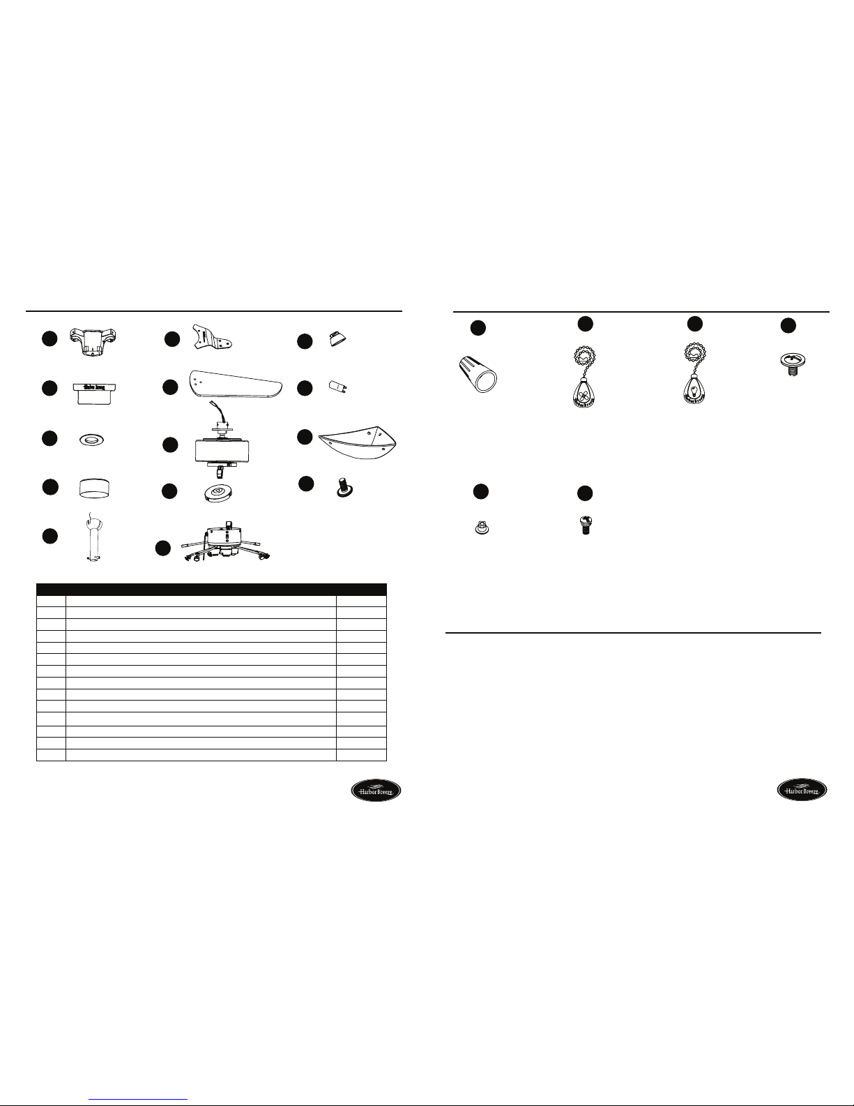
HARDWARE CONTENTS (shown actual size)
Blade Bracket Screw
Qty. 6
Wire Connector
Qty. 4
AA
BB
CC
K
4
PACKAGE CONTENTS
F
A
I
H
G
D
C
B
E
J
L
N
Fan Pull Chain
Extension
Qty. 1
(NOT TO SCALE)
Light Pull Chain
Extension
Qty. 1
(NOT TO SCALE)
EE
Blade Screw
Qty. 9
M
Lowes.com/harborbreeze
PART DESCRIPTION QUANTITY
A Mounting Bracket 1
B Canopy 1
C Canopy Cover 1
D Yoke Cover 1
E Downrod 1
F Blade Bracket 3
G Blade 3
H Motor Housing Assembly 1
I Switch Housing Cover (preassembled to Motor Housing Assembly (H)) 1
J Light Kit Assembly 1
K Bulb Cover 3
L Bulb 3
M Glass Bowl 1
N Finial (preassembled to Light Kit Assembly (J)) 6
Lowes.com/harborbreeze
Decorative Nut
Qty. 9
DD
FF
PREPARATION
Estimated Assembly Time: 45 minutes
Before beginning assembly of product, make sure all parts are present. Compare parts with package
contents list and hardware contents list. If any part is missing or damaged, do not attempt to
assemble the product.
Tools Required for Assembly (not included): Phillips screwdriver, step ladder, electrical tape, pliers,
wire cutters, wire strippers.
 Loading...