

Harbor Breeze 00892 User Manual
1
Español p. 19
CLASSIC STYLE
CEILING FAN
ITEM #0076253
MODEL #00892
Serial Number Purchase Date
Harbor Breeze® is a registered trademark of LF,
LLC. All Rights Reserved.
Questions, problems, missing parts? Before returning to your retailer,
call our customer service department at 1-800-643-0067, 8 a.m. - 6 p.m., EST,
Monday - Thursday, 8 a.m. - 5 p.m., EST Friday
PB18424
ATTACH YOUR RECEIPT HERE
UL MODEL #CSS36
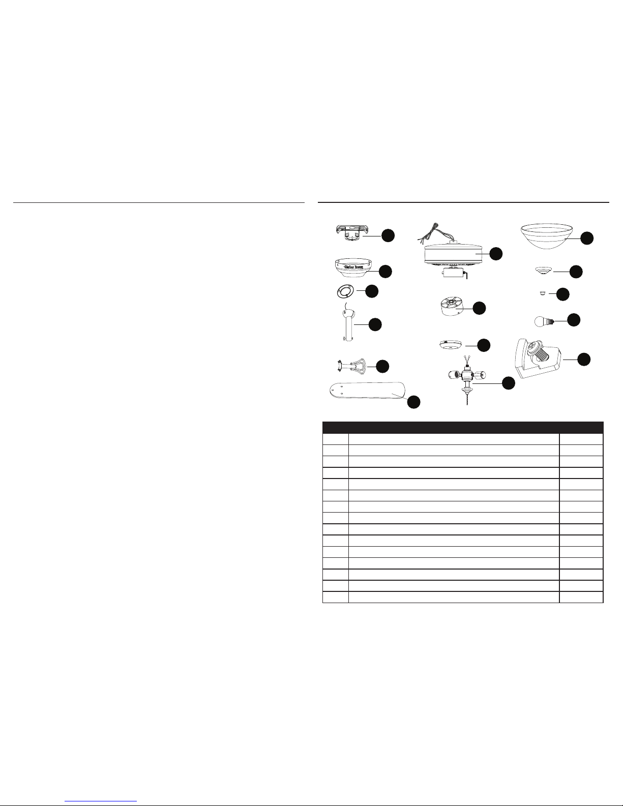
TABLE OF CONTENTS
Package Contents...................................................................................................... 3
Hardware Contents..................................................................................................... 4
Preparation ............................................................................................................... 4
Safety Information....................................................................................................... 5
Assembly Instructions ............................................................................................... 6
Downrod style fan mounting ...................................................................................... 7
Closemount style fan mounting ................................................................................. 8
Operating Instructions ............................................................................................... 16
Care and Maintenance ............................................................................................. 17
Troubleshooting......................................................................................................... 17
Warranty..................................................................................................................................18
Replacement Parts List ............................................................................................. 18
32
PACKAGE CONTENTS
PART DESCRIPTION QUANTITY
A Mounting Bracket (preassembled to canopy (B)) 1
B Canopy 1
C Canopy Cover (preassembled to canopy (B)) 1
D Downrod Assembly 1
E Blade Bracket 5
F Blade 5
G Motor Housing 1
H Switch Housing (preassembled to motor housing (G)) 1
I Switch Housing Cover 1
J Light Kit 1
K Glass Bowl 1
L Bowl Cap (preassembled to light kit (J)) 1
M Finial (preassembled to light kit (J)) 1
N Bulb 2
O Rubber Motor Stopper with Screw 3
B
A
C
F
G
H
D
I
J
K
L
E
)
N
O
M
54
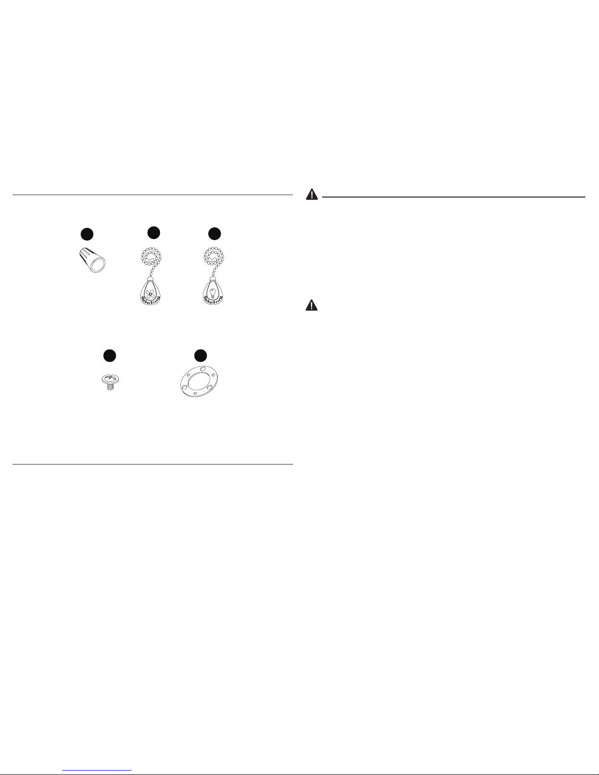
HARDWARE CONTENTS
SAFETY INFORMATION
READ AND SAVE THESE INSTRUCTIONS
Please read and understand this entire manual before attempting to assemble, operate or install the product.
• When using an existing outlet box, be sure the box is securely attached to the building structure and can
support the full weight of the fan, so to avoid potential serious injury or death.
• All wiring must be in accordance with the National Electrical Code “ANSI/NFPA 70-1999” and local electrical
codes. Electrical installation should be performed by a qualied licensed electrician.
• DO NOT use bulbs with wattage greater than the maximum value stated on the xture and in this manual.
Using a higher wattage bulb than specied will increase xture temperature and cause risk of re.
• Disconnect the electrical supply circuit to the fan before installing kit.
• Electrical diagrams are for reference only.
• The net weight of this fan including the light kit is: 13.27 lbs.
WARNING
• ELECTRIC SHOCK HAZARD - To reduce the risk of electric shock, do not use this fan with any solid-state
speed control device.
• ELECTRIC SHOCK HAZARD - To reduce the risk of electric shock, make sure the electricity has been turned
off at the circuit breaker or fuse box before beginning installation.
• PERSONAL INJURY HAZARD - To reduce the risk of personal injury, do not bend the blade brackets when
installing the brackets, balancing the blades, or cleaning the fan. DO NOT insert foreign objects in between
the rotating fan blades.
• FIRE, ELECTRIC SHOCK OR PERSONAL INJURY HAZARD - To reduce the risk of re, electric shock,
or personal injury, mount to an outlet box marked “ACCEPTABLE FOR FAN SUPPORT OF 35 lbs OR
LESS” and use the mounting screws provided with the outlet box. Most outlet boxes commonly used for
the support of lighting xtures are not acceptable for fan support and may need to be replaced. Consult a
qualied licensed electrician if in doubt.
• PERSONAL INJURY HAZARD - To reduce the risk of injury to persons, install fan so the blades are 7 ft.
above the oor.
PREPARATION
Before beginning assembly of product, make sure all parts are present. Compare parts
with package contents list and hardware contents list. If any part is missing or damaged,
do not attempt to assemble the product.
Estimated Assembly Time: 45 minutes.
Tools Required for Assembly (not included): Phillips screwdriver, step ladder, electrical
tape, pliers, wire cutters, wire strippers.
Helpful Tools (not included): Electrical circuit tester.
CC
DD
BB
EE
AA
Wire Connector
Qty. 4
Blade Screw
Qty. 16
Light Pull Chain
Extension
Qty. 1
Fan Pull Chain
Extension
Qty. 1
Rubber Gasket
Qty. 1
(not to scale)
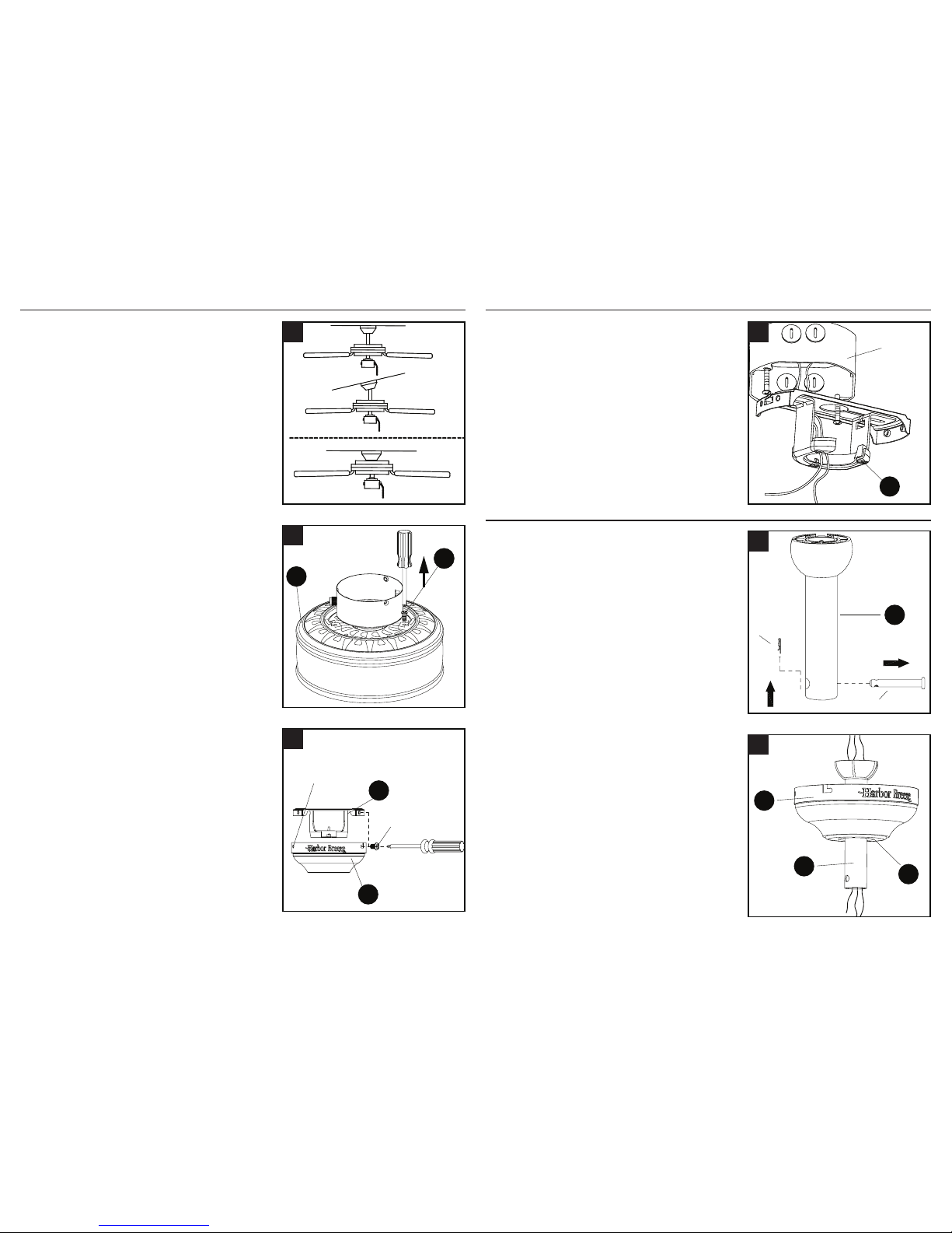
ASSEMBLY INSTRUCTIONS
1. Determine mounting method to use.
A - Downrod Mount (standard or angled ceiling)
B - Closemount (normal ceiling only)
IMPORTANT: lf using the angle mount, check
to make sure the ceiling angle is not steeper
than 20°.
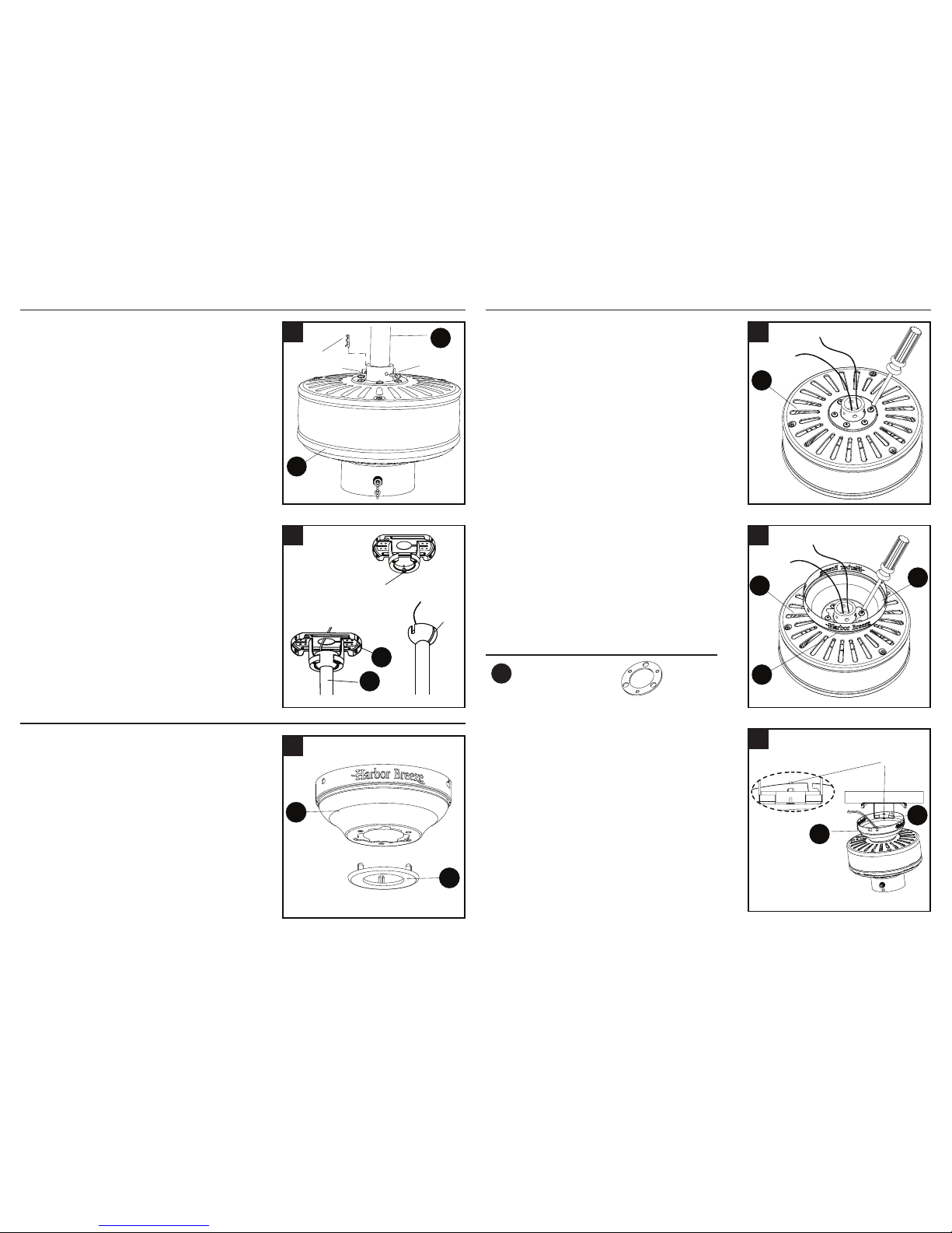
2. Remove the rubber motor stoppers (O) from
the bottom of the fan motor assembly (G)
by loosening the three screws. Discard the
rubber motor stopper and screws.
3. Remove the mounting bracket (A) from the
canopy (B) by loosening the four screws
on the top of the canopy (B). Remove the
two non-slotted screws and save, then
loosen the slotted screws. This will enable
you to remove the mounting bracket (A).
76
4. Install the mounting bracket (A) to the outlet box
(not included), sliding the mounting bracket (A)
over the two outlet box screws (not included).
Securely tighten the two outlet box screws.
IMPORTANT: If using the angle mount, make
sure open end of mounting bracket (A) is
installed facing the ceiling.
A
B
1
A
Outlet
box
4
D
clip
pin
1
C
B
D
2
G
O
2
A
B
Loosen but
do not remove
Remove
and save
3
ASSEMBLY INSTRUCTIONS
DOWNROD STYLE FAN MOUNTING
1. Remove pin and clip from downrod assembly
(D) and save.
2. Insert downrod assembly (D) through
canopy (B), canopy cover (C). Thread
wires from the motor housing assembly (G)
through downrod (D).
Follow mounting instructions for “Downrod
Style Fan Mounting” or “Closemount Style
Fan Mounting”, depending on mounting
method (A or B) chosen in step 1 on previous
page.
98
DOWNROD STYLE FAN MOUNTING
3. Loosen the two set screws from the yoke on
the top of the motor housing (G). Slip downrod
assembly (D) into housing yoke, aligning holes
in downrod assembly (D) and yoke. Insert the
pin through yoke and downrod assembly (D).
Insert clip into pin until it snaps into place.
Tighten set screws.
4. Install hanger ball on the top of downrod (D)
into mounting bracket (A) opening. Rotate fan
until slot on hanger ball engages the tab on
the mounting bracket (A).
1. Remove the canopy cover (C) from the
bottom of the canopy (B).
D
G
clip
pin
set
screw
3
A
D
slot
tab
4
B
C
1
WARNING: Be careful when aligning the tab
to the slot! If not fully engaged, there is a
possibility of fan falling, which may result in
serious injury or death.
CLOSEMOUNT STYLE FAN MOUNTING
CLOSEMOUNT STYLE FAN MOUNTING
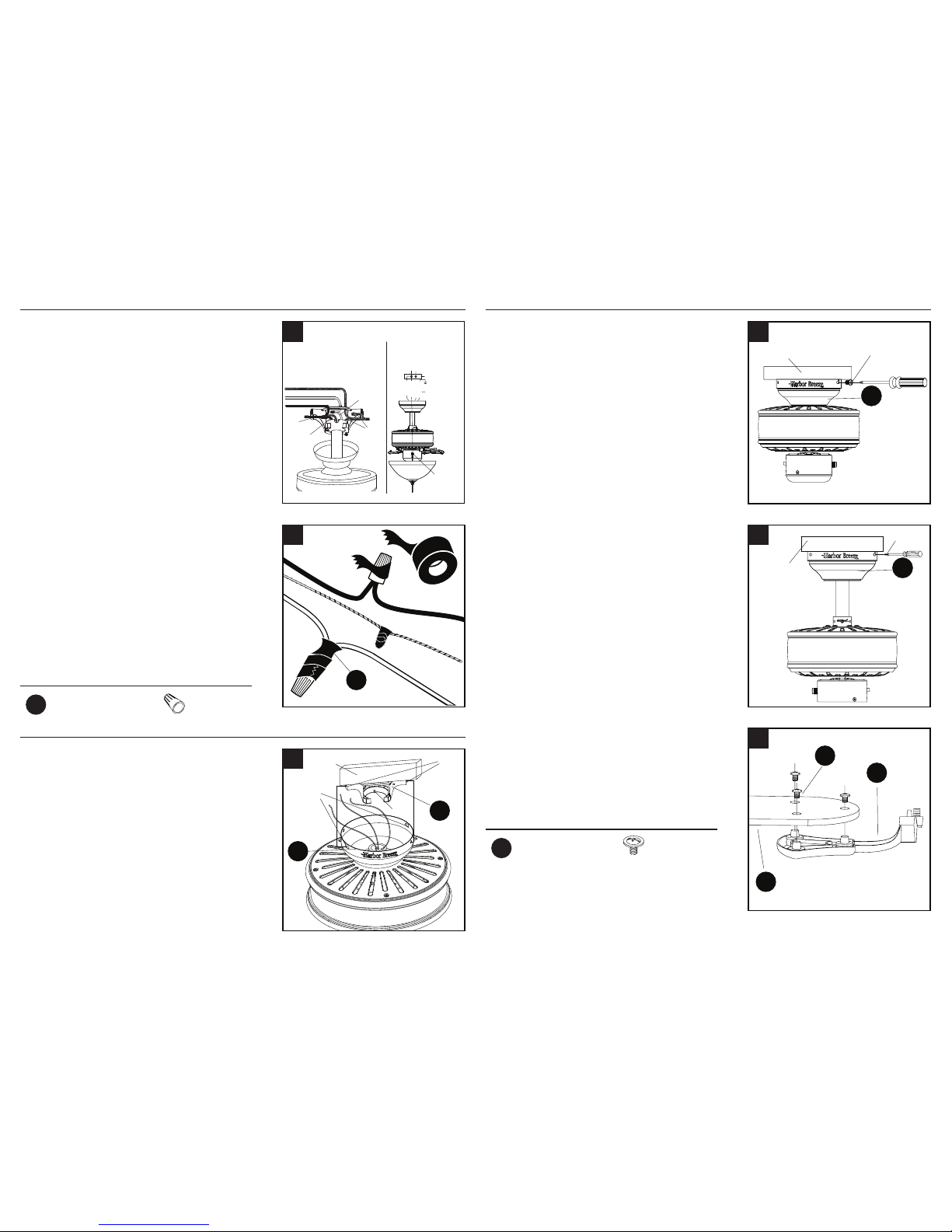
2. Remove three of the six screws and
lockwashers (every other one) securing
the motor collar to the top of the fan motor
housing (G).
3. Place the rubber gasket (EE) over the
remaining screws. Pull wires through hole in
canopy (B), and attach canopy (B) to motor
housing (G). Align the mounting holes with
the holes in the motor and fasten using the
three screws removed in previous step.
Tighten the screws securely.
4. Hang the fan on the hook on the mounting
bracket (A) using one of the non-slotted
holes in the canopy (B).
G
2
G
EE
B
3
B
A
hook
4
You may now proceed to the WIRING section
on page 10.
Hardware Used
Rubber gasket x 1
EE
1110
WIRING
2. To connect wires, twist wire ends together
and screw wire with wire connectors (AA) in a
clockwise direction. Tape the wire connectors
(AA) and wires together with electrical tape (not
included). Be sure no bare wire or wire strands
are visible after making connection.
1. Remove the fan from the hook on the
mounting bracket (A). Align the locking slots
of the canopy (B) with the two screws in the
mounting bracket (A). Push up to engage
the slots and turn clockwise to lock in place.
Immediately tighten the two screws rmly.
AA
2
outlet
box
screws
hook
locking
slots
A
B
1
Place GREEN and WHITE connections on
opposite side of box from the BLACK and
BLUE connections. The splices should be
turned upward and pushed carefully up into
the outlet box.
FINAL INSTALLATION
FINAL INSTALLATION
2. Install the two screws that were removed in
previous step and tighten securely.
3. Directly align the locking slots of the canopy
(B) with the two screws in the mounting
bracket (A). Push up to engage the slots and
turn clockwise to lock in place. Immediately
tighten the two screws rmly. Install the two
screws that were removed in previous step
and tighten securely.
4. Attach a blade (F) to a blade bracket (E)
using the blade screws (DD).
Repeat for remaining blade assemblies.
B
screw
outlet box
2
B
screw
outlet box
3
E
F
DD
4
Hardware Used
Blade Screw x 16
DD
1. Connect the BLACK and BLUE wires from
the fan to the house BLACK wire. Connect
the WHITE wire from fan to the house WHITE
wire. Connect all GROUNDED (GREEN)
wires together from fan to the house GREEN/
GROUND wire.
NOTE: BLACK wire is hot power for fan.
BLUE wire is hot power for light kit. WHITE
wire is common for fan and light kit. GREEN
wire is ground wire. If house wires are
different colors than referred to above, stop
immediately. Consult a licensed electrician to
determine proper wiring.
Hardware Used
Wire Connector x 4
AA
If you installed the fan with “Closemount Style
Fan Mounting”, continue to Steps 1 and 2. If
you installed the fan with “Downrod Style Fan
Mounting”, skip to Step 3.
Grounded/Green
Black
White
Grounded/
Green
Black
Blue
White
outlet box
blue
black
white
green
white
Green/
Grounded
black
Supply Circuit
speed
switch
1
You may now proceed to Step 4.
 Loading...