

Harbor Breeze 00723 User Manual
1
LYNSTEAD
CEILING FAN
ITEM #0807420
MODEL #00723
Español p. 14
Serial Number
Purchase Date
Harbor Breeze ® is a registered trademark of LF,
LLC. All Rights Reserved.
Questions, problems, missing parts? Before returning to your retailer, call our customer
service department at 1-800-643-0067, 8 a.m. - 6 p.m., EST, Monday - Thursday,
8 a.m. - 5 p.m., EST, Friday.
EB16372
ATTACH YOUR RECEIPT HERE
UL #LSD52
COVER - Page 1
Page 12

3
2
TABLE OF CONTENTS
Safety Information............................................................................................................... 3
Package Contents............................................................................................................... 4
Hardware Contents...............................................................................................................5
Preparation ......................................................................................................................... 5
Assembly Instructions ......................................................................................................... 6
Operating Instructions ........................................................................................................ 12
Care and Maintenance ....................................................................................................... 12
Troubleshooting................................................................................................................... 12
Warranty.............................................................................................................................. 13
Replacement Parts List ...................................................................................................... 13
SAFETY INFORMATION
WARNING
READ AND SAVE THESE INSTRUCTIONS
Please read and understand this entire manual before attempting to assemble, operate or install the
product.
• When using an existing outlet box, be sure the box is securely attached to the building structure
and can support the full weight of the fan, so as to avoid potential serious injury or death.
• All wiring must be in accordance with the National Electrical Code “ANSI/NFPA 70-1999” and local
electrical codes. Electrical installation should be performed by a qualied licensed electrician.
• Electrical diagrams are for reference only.
• Do not use bulbs that have a wattage greater than the maximum value stated on the xture and
in this manual. Using a higher wattage bulb than specied will increase xture temperature and
cause risk of re. Disconnect the electrical supply circuit to the fan before installing light kit.
• After making the wire connections, the wires should be spread apart with the grounded conductor
and the equipment-grounding conductor on one side of the outlet box and the ungrounded
conductor on the other side of the outlet box.
• Splices after being made should be turned upward and pushed carefully up into the outlet box.
• All set screws must be checked and retightened during and before installation.
• The net weight of this fan including the light kit is: 26.4 lbs.
• ELECTRIC SHOCK HAZARD - To reduce the risk of electric shock, do not use this fan with
any solid-state speed control device.
• ELECTRIC SHOCK HAZARD - To reduce the risk of electric shock, make sure the electricity
has been turned off at the circuit breaker or fuse box before beginning installation.
• PERSONAL INJURY HAZARD - To reduce the risk of injury to persons, install fan so that the
blade is at least 7 ft. above the oor.
• FIRE, ELECTRIC SHOCK OR PERSONAL INJURY HAZARD - To reduce the risk of re,
electric shock, or personal injury, mount to an outlet box marked “ACCEPTABLE FOR FAN
SUPPORT OF 35 lbs OR LESS” and use the mounting screws provided with the outlet box.
Most outlet boxes commonly used for the support of lighting xtures are not acceptable for fan
support and may need to be replaced. Consult a qualied licensed electrician if in doubt.
• PERSONAL INJURY HAZARD - Reduce the risk of personal injury, do not bend the blade
brackets when installing the brackets, balancing the blades or cleaning the fan. DO NOT insert
foreign objects in between the rotating fan blades.
Page 3
Page 2
54
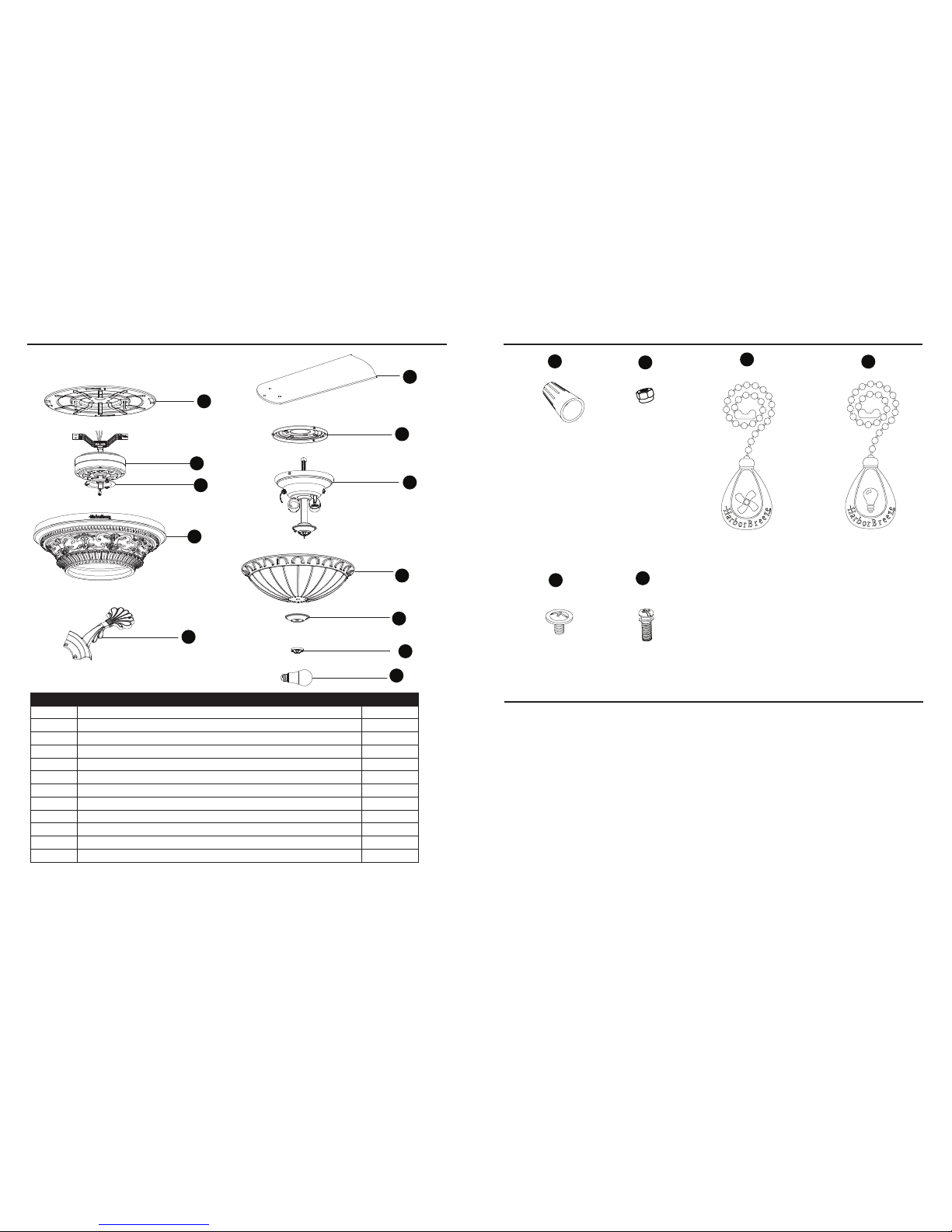
HARDWARE CONTENTS (shown actual size)
PREPARATION
Before beginning assembly of product, make sure all parts are present. Compare parts with package
contents list and hardware contents list. If any part is missing or damaged, do not attempt to
assemble the product.
Estimated Assembly Time: 45 minutes
Tools Required for Assembly (not included): Phillips screwdriver, step ladder, electrical tape, pliers,
wire cutters, wire strippers.
PACKAGE CONTENTS
PART DESCRIPTION QUANTITY
A Mounting Plate 1
B Motor 1
C Switch Housing Plate (preassembled to motor (B)) 1
D Motor Housing 1
E Blade Bracket 5
F Blade 5
G Switch Housing 1
H Light Kit 1
I Glass Bowl 1
J Bowl Cap (preassembled to light kit (H)) 1
K Finial (preassembled to light kit (H)) 1
L Bulb 2
B
A
C
F
G
H
D
I
J
K
L
E
CC
DD
BB
EE
FF
AA
Wire Connector
Qty. 3 + 1 extra
Lock Nut
Qty. 3
Blade Screw
Qty. 15 + 1 extra
Blade Bracket Screw
with Washer
Qty. 10 + 1 extra
Fan Pull Chain
Extension
Qty. 1
Light Pull Chain
Extension
Qty. 1
Page 4 Page 5
AA
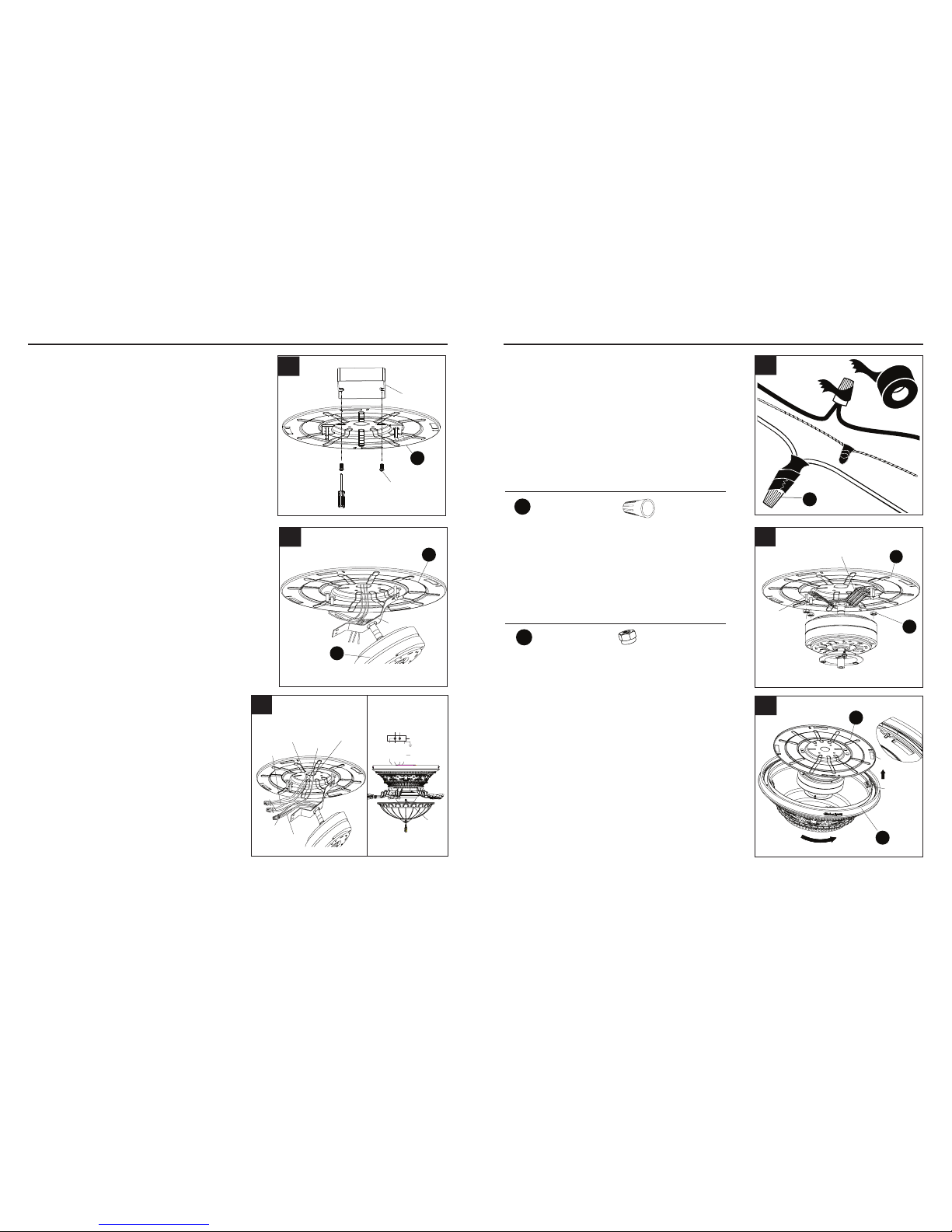
4. Tape the wire connectors (AA) and wires together.
The wires should be spread apart with the
grounded conductor and the equipment-grounding
conductor on one side of the outlet box and the
ungrounded conductor on the other side of the
outlet box. Be sure no bare wire or wire strands are
visible after making connection. Place green and
white connections on opposite side of box from the
black and blue connections. The splices should
be turned upward and pushed carefully up into the
outlet box.
A
Outlet box
Screw
6
7
ASSEMBLY INSTRUCTIONS ASSEMBLY INSTRUCTIONS
NOTE: Black wire is hot power for fan.
Blue wire is hot power for light kit. White
wire is common for fan and light kit. Green
wire is grounded wire. lf house wires are
different colors than referred to above, stop
immediately. A professional electrician is
recommended to determine proper wiring.
1. Securely attach the mounting plate (A) to the
outlet box (not included) using two screws
(supplied with outlet box). Pull the black, white
and grounded wires out of the outlet box
through the hole in the mounting plate (A) and
lay them to the side.
5. Lift the motor bracket so the threaded studs on the
mounting plate (A) protrude through the slots in the
motor bracket. Securely tighten the three lock nuts
(BB) onto the threaded studs.
NOTE: Lightly shake the motor bracket to ensure
the assembly is tight.
2. Carefully lift the motor (B) and engage the slot
in the preassembled bracket with the hook
on the mounting plate (A) so it is securely
suspended.
3. Connect the supply GROUNDED/GREEN wire to
the GREEN/GROUNDED wires from the motor
bracket using the wire connector (AA). Connect
the fan motor WHITE wire to the supply WHITE
wire using the wire connector (AA). Connect the
fan motor BLACK and BLUE wires to the supply
BLACK wire using the wire connector (AA).
E
Threaded
stud
Motor bracket
BB
A
5
Page 6 Page 7
A
B
Bracket
2
1
B
Grounded/
Green
Black
White
Green
Black
Blue
White
outlet box
blue
black
white
green
white
GREEN/
black
Supply circuit
speed
switch
GROUNDED
3
Hardware Used
4
NOTE: Make sure the outlet box is securely
installed in place such that it is able to support
at least the fan weight.
Hardware Used
x 3
Lock Nut
BB
x 3 + 1 extra
Wire Connector
AA
6. Align the four clips on the inside of the motor
housing (D) with the four slots on the outer
edge of the mounting plate (A). Twist the motor
housing (D) clockwise until it stops to hold on
the mounting plate (A).
Clip
Slot
A
D
6
G
G
Screw
8 9
ASSEMBLY INSTRUCTIONS ASSEMBLY INSTRUCTIONS
Hardware Used
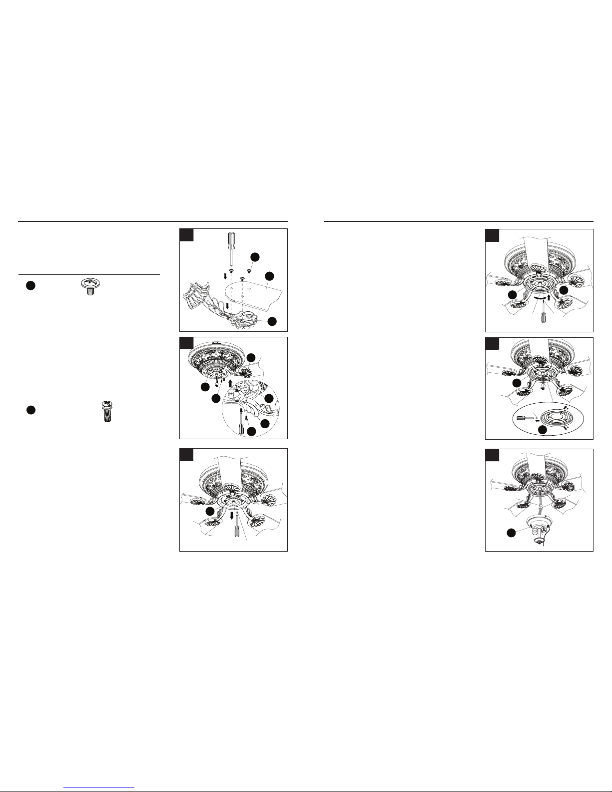
7. Attach a blade (F) to a blade bracket (E) using
the blade screws (EE). Tighten each blade
screw (EE) securely. Repeat for the remaining
blades (F).
10. Insert the wires from the motor (B) through the
middle hole in the switch housing (G). Attach
the switch housing (G) to the switch housing
plate (C). Align the keyslot holes and twist to
lock. Replace the screw previously removed
(Step 9, page 8) and tighten all three screws.
8. Align the holes between the blade bracket
(E) and motor (B). Install the blade assembly
to the motor (B) using blade bracket screws
with washers (FF). Tighten each blade bracket
screw with washer (FF) securely. Repeat for the
remaining blade assemblies.
11. Remove the preassembled screws from the
switch housing (G).
F
E
EE
7
Screw
Keyslot
hole
G
C
10
E
E
B
B
FF
FF
8
11
9. Loosen two screws and remove one screw from
the switch housing plate (C).
C
Screw
9
Hardware Used
EE
Blade Screw x 15 + 1 extra
FF
Blade Bracket Screw
with Washer
10 + 1 extra
12. Connect male plug from fan to female plug from
the light kit (H).
Male plug
Female
plug
H
12
Page 8 Page 9
 Loading...