

Harbor Breeze 00598 User Manual
Español p. 16
SARATOGA CEILING FAN
ITEM #0883772
MODEL #00598
Serial Number
Purchase Date
Harbor Breeze ® is a registered trademark of LF,
LLC. All Rights Reserved.
Questions, problems, missing parts? Before returning to your retailer, call our customer
service department at 1-800-643-0067, 8 a.m. - 6 p.m., EST, Monday - Thursday
8 a.m. - 5 p.m., EST Friday
AB17943
ATTACH YOUR RECEIPT HERE
UL MODEL #48-STG
3
2
TABLE OF CONTENTS
Safety Information............................................................................................................... 2
Package Contents............................................................................................................... 4
Hardware Contents...............................................................................................................5
Preparation ......................................................................................................................... 5
Assembly Instructions...........................................................................................................6
Operating Instructions ........................................................................................................ 13
Care and Maintenance ....................................................................................................... 14
Troubleshooting................................................................................................................... 14
Warranty.............................................................................................................................. 15
Replacement Parts List ...................................................................................................... 15
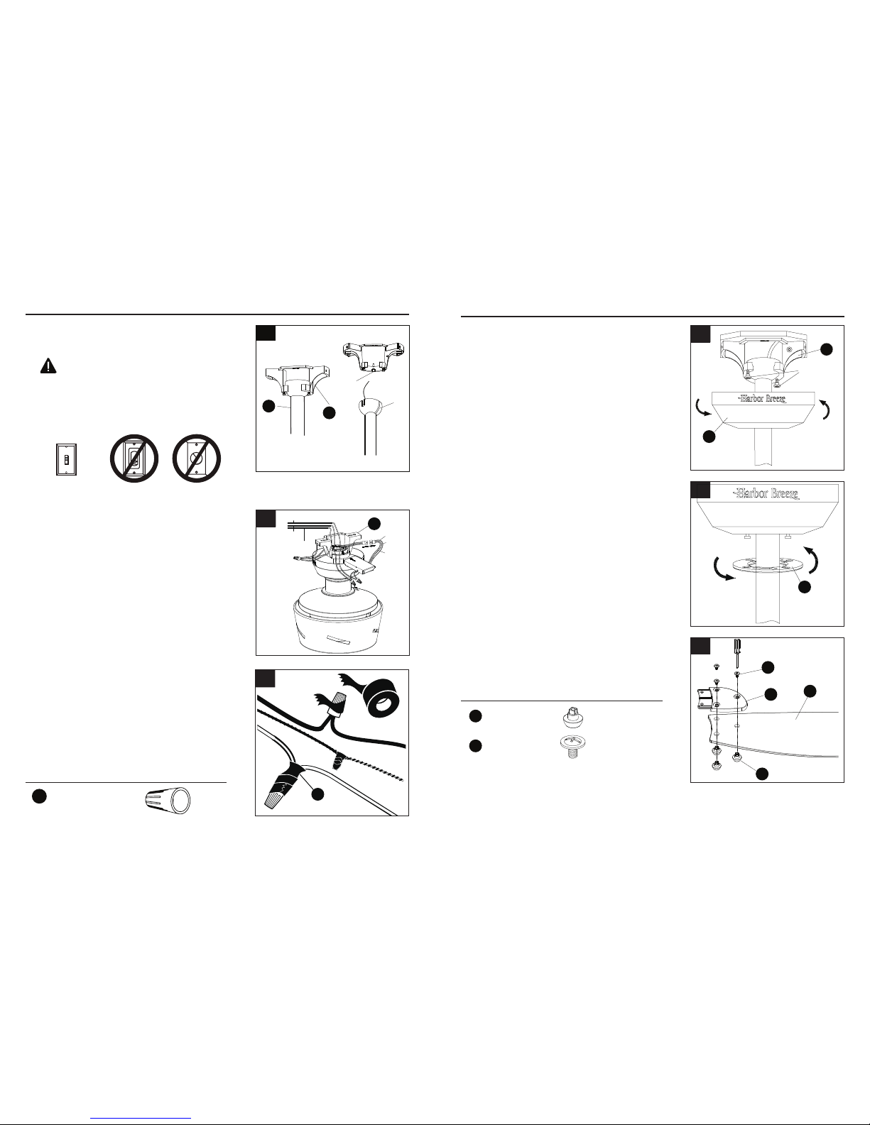
SAFETY INFORMATION
WARNING
CAUTION
READ AND SAVE THESE INSTRUCTIONS
Please read and understand this entire manual before attempting to assemble, operate or
install the product.
• When using an existing outlet box, be sure the box is securely attached to the building structure
and can support the full weight of the fan, so to avoid potential serious injury or death.
• All wiring must be in accordance with the National Electrical Code “ANSI/NFPA 70” and local
electrical codes. Electrical installation should be performed by a qualied licensed electrician.
• DO NOT use bulbs with wattage greater than the maximum value stated on the xture and in
this manual. Using a higher wattage bulb than specied will increase xture temperature and
cause risk of re.
• Disconnect the electrical supply circuit to the fan before installing kit.
• Electrical diagrams are for reference only.
• Suitable for use in damp locations.
• Use only with light kits marked suitable for use in damp locations.
• The net weight of this fan including the light kit is: 18.96 lbs.
• Suitable for use with solid-state speed controls.
• WARNING - To reduce the risk of electric shock, this fan must be installed with an isolating wall
control/switch.
• ELECTRIC SHOCK HAZARD - To reduce the risk of electric shock, make sure the electricity
has been turned off at the circuit breaker or fuse box before beginning installation.
• PERSONAL INJURY HAZARD - To reduce the risk of injury to persons, install fan so that the
blades are 7 ft. above the oor.
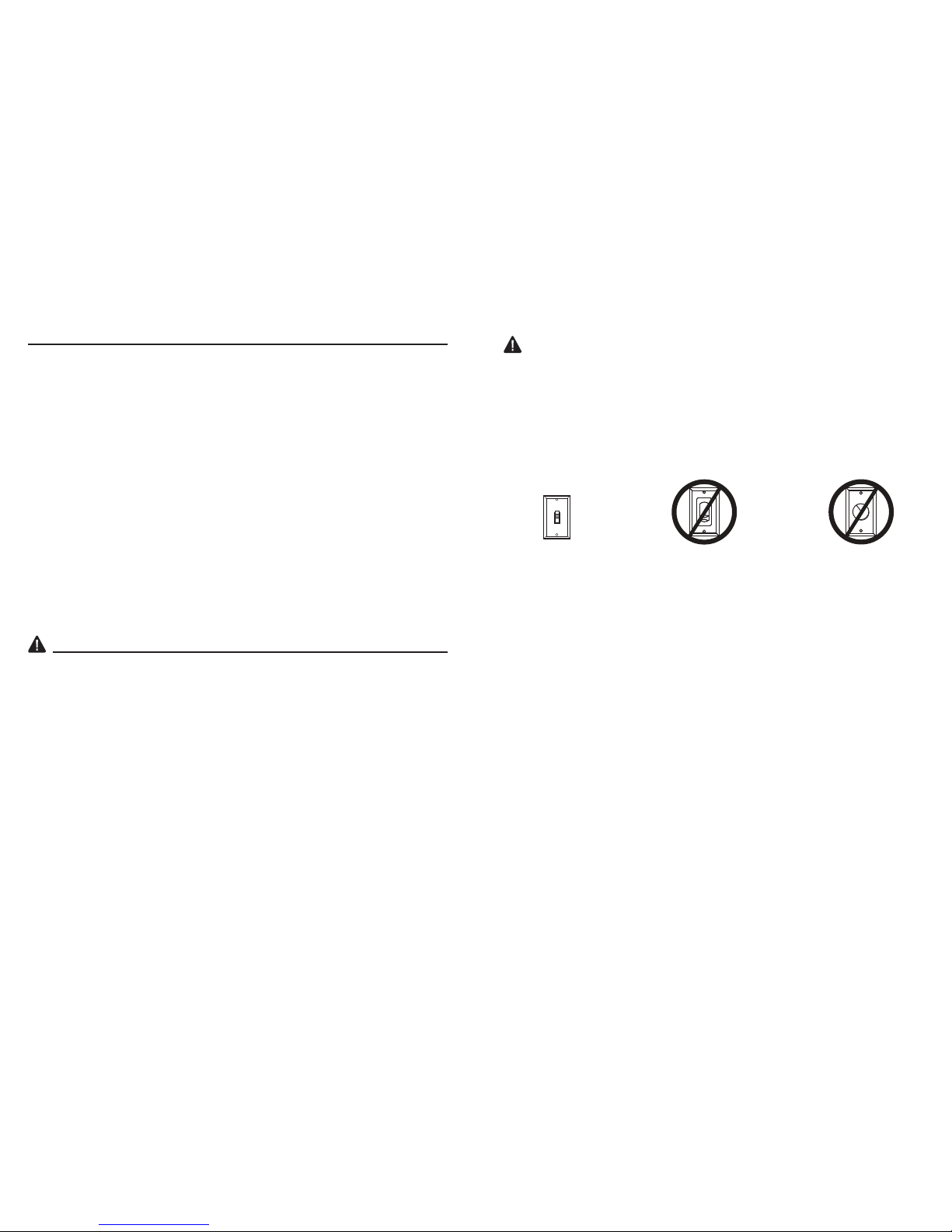
• ELECTRIC SHOCK HAZARD - Do not install this fan with variable speed wall control or wallmounted dimmer switch. It will permanently damage the fan’s remote control receiver and cause
the fan’s functions to fail.
ON
ON / OFF switch NO Variable speed wall control NO Dimmer switch
• FIRE, ELECTRIC SHOCK OR PERSONAL INJURY HAZARD - To reduce the risk of re, electric
shock, or personal injury, mount to an outlet box marked “ACCEPTABLE FOR FAN SUPPORT
OF 35.1 LBS. OR LESS” and use the mounting screws provided with the outlet box. Most outlet
boxes commonly used for the support of lighting xtures are not acceptable for fan support and
may need to be replaced. Consult a qualied licensed electrician if in doubt.
• PERSONAL INJURY HAZARD - To reduce the risk of personal injury, do not bend the blade
arms when installing the brackets, balancing the blades, or cleaning the fan. DO NOT insert
foreign objects in between the rotating fan blades.
Page 3
Page 2
This equipment has been tested and found to comply with the limits for a Class B digital device,
pursuant to Part 15 of the FCC Rules. These limits are designed to provide reasonable protection
against harmful interference in a residential installation. This equipment generates, uses and can
radiate radio frequency energy and, if not installed and used in accordance with the instructions,
may cause harmful interference to radio communications. However, there is no guarantee
that interference will not occur in a particular installation. If this equipment does cause harmful
interference to radio or television reception, which can be determined by turning the equipment off
and on, the user is encouraged to try to correct the interference by one or more of the following
measures:
Reorient or relocate the receiving antenna.
Increase the separation between the equipment and receiver.
Connect the equipment into an outlet on a circuit different from that to which the receiver is
connected.
Consult the dealer or an experienced radio/TV technician for help.
CAUTION: Any changes or modications not expressly approved by the grantee of this device
could void the user’s authority to operate the equipment.
This device complies with Part 15 of the FCC Rules. Operation is subject to the following two
conditions:
(1) This device may not cause harmful interference, and (2) this device must accept any
interference received, including interference that may cause undesired operation.
A 1
B 1
C 1
D 1
E 1
F 5
G 5
H 1
I 1
J 1
K 1
L 1
M 1
54
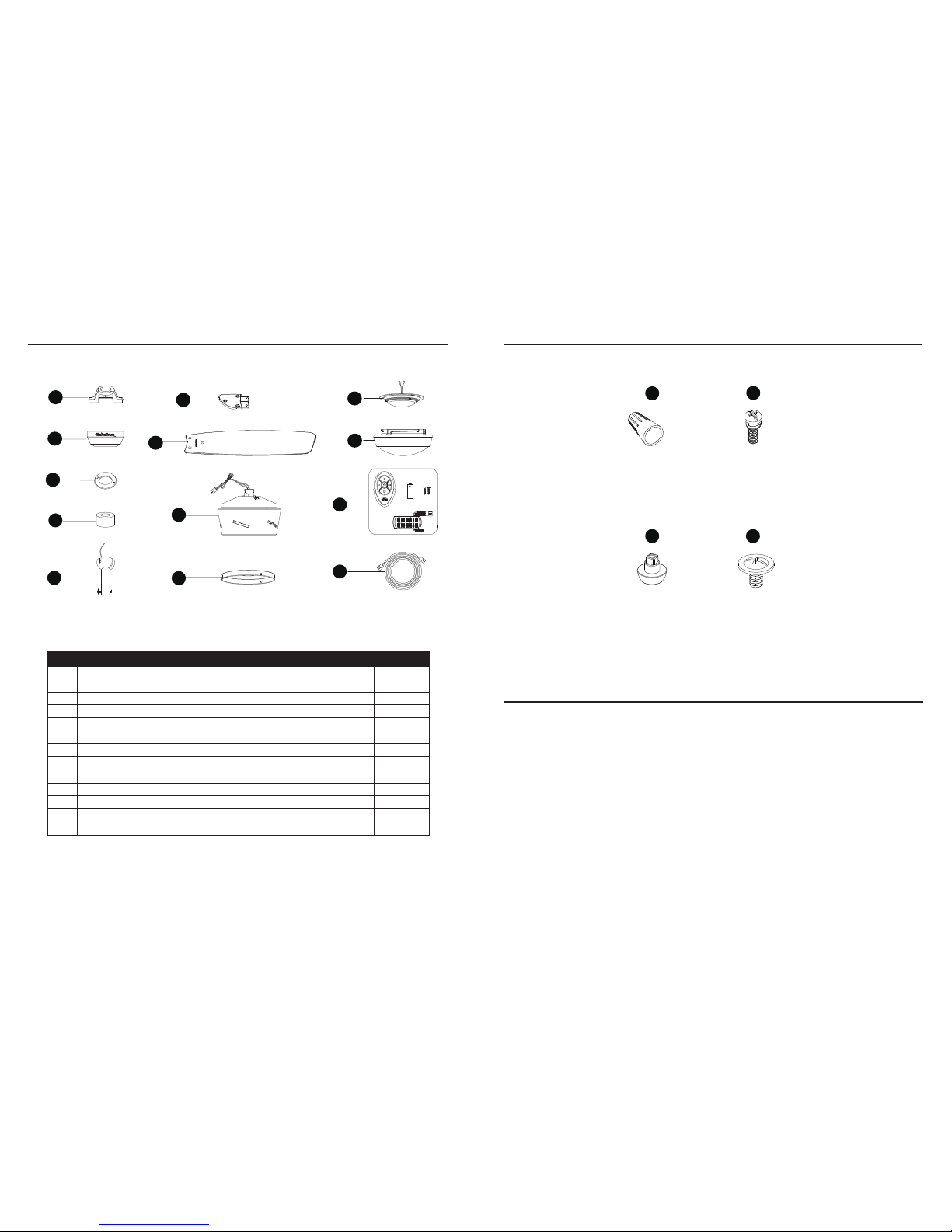
HARDWARE CONTENTS (shown actual size)
PREPARATION
Before beginning assembly of product, make sure all parts are present. Compare parts with package
contents list and hardware contents list. If any part is missing or damaged, do not attempt to
assemble the product.
Estimated Assembly Time: 45 minutes.
Tools Required for Assembly (not included): Phillips screwdriver, step ladder, electrical tape, pliers,
wire cutters, wire strippers.
Helpful Tools (not included): Electrical circuit tester.
PACKAGE CONTENTS
A
Mounting Bracket
Canopy
Canopy Cover
Yoke Cover
Downrod
Blade Arm
Blade
Fan Motor Assembly
Fitter Plate
Light Fixture
Glass
Remote Pack
Lead Wire
PART
DESCRIPTION
QUANTITY
B
A
C
D
E
G
F
H
I
K
J
L
M
BB
CC
DD
AA
Wire Connector
Qty. 3 + 1 extra
Blade Screw
Qty. 15 + 1 extra
Blade Arm Screw
with Washer
Qty. 10 + 1 extra
Decorative Nut
Qty. 15
A
Outlet box
6 7
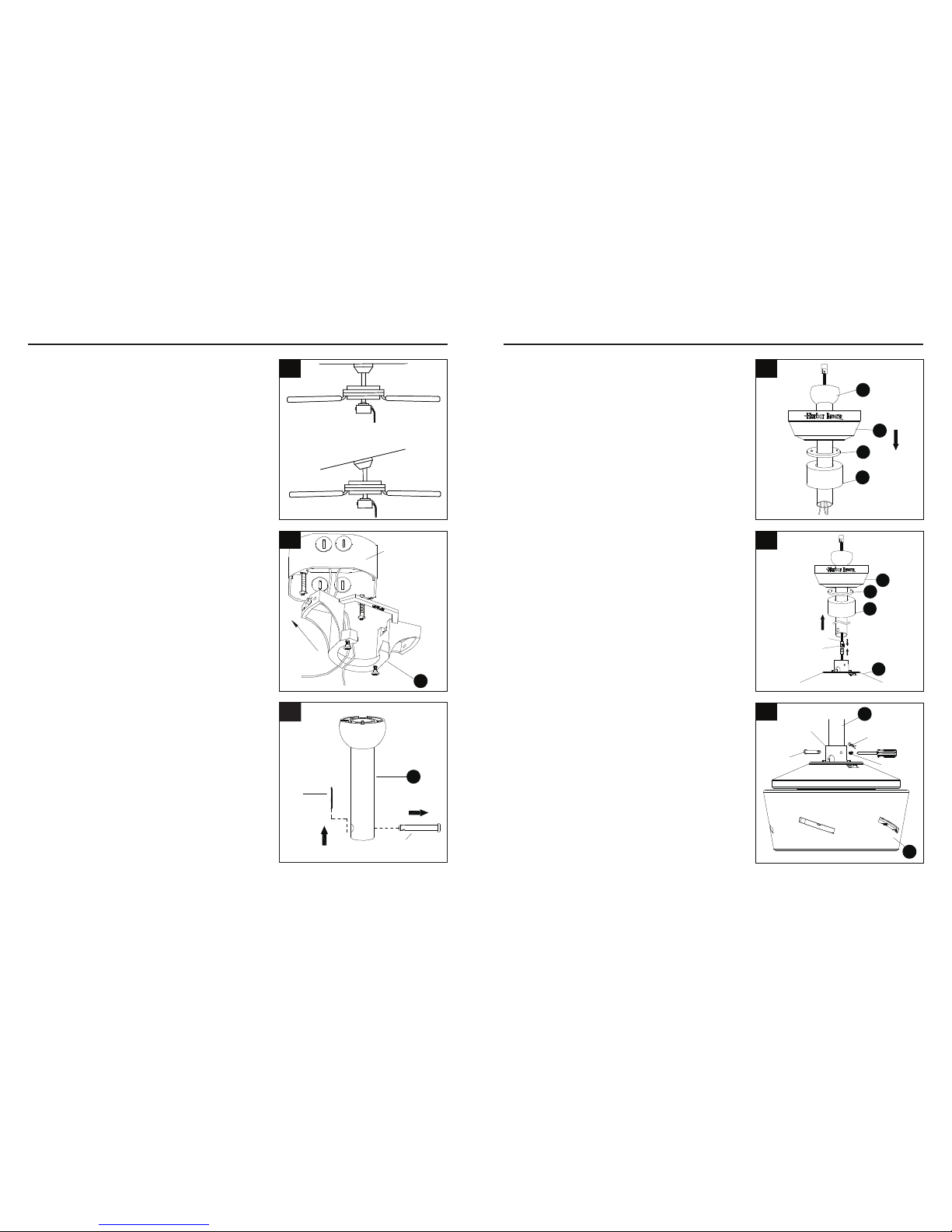
ASSEMBLY INSTRUCTIONS ASSEMBLY INSTRUCTIONS
1. Determine mounting method.
Downrod Mount (standard or angled ceiling)
Important: lf angle mounting, check to make sure the
ceiling angle is not steeper than 20°.
3. Remove preassembled pin and clip from downrod (E).
Save for later use.
5. Loosen preassembled set screws from yoke on fan
motor assembly (H). Slip downrod (E) into housing
yoke, aligning holes on both parts. Insert previously
removed pin through holes on yoke and downrod (E),
then insert previously removed clip into pin until it
snaps into place. Tighten set screws.
E
Pin
Clip
3
2. Install mounting bracket (A) to outlet box (not included
by sliding mounting bracket (A) over the two outlet box
screws (not included). Securely tighten two outlet box
screws.
Important: If angle mounting, make sure open end of
mounting bracket (A) is installed facing the higher part
of the ceiling.
4a. STANDARD DOWNROD INSTALLATION:
Insert downrod (E) through canopy (B), canopy
cover (C), and yoke cover (D). Thread wires from fan
motor assembly through downrod (E).
2
1
E
C
B
D
4a
E
H
Clip
Set screw
Pin
Yoke
5
4b. EXTENDED DOWNROD INSTALLATION:
If you are installing the fan with a longer downrod
(sold separately), insert it through the canopy (B),
canopy cover (C) and yoke cover (D). Then, thread
lead wire (N) through the downrod and connect the
MALE plug from the top of motor assembly (H) to the
FEMALE plug from the lead wire (N).
C
B
D
Female Plug
Male Plug
H
4b
NOTE: The male plug of the lead wire (N) should
extend out of the other end of the downrod.
NOTE: The remainder of the instructions will
reference downrod assembly (D), but note all of
the instructions are applicable even if an accessory
downrod was used.
8 9
ASSEMBLY INSTRUCTIONS
7. Insert the receiver from the remote pack (L) into the
mounting bracket (A) with the at side towards the
ceiling. Connect BLACK wire from receiver to BLACK
wire from ceiling. Connect WHITE wire from receiver
to WHITE wire from ceiling. Connect all GROUNDED
(GREEN) wires together from fan to GREEN/
GROUNDED wire from ceiling. Connect the male plug
from fan to female plug from the receiver together.
NOTE: BLACK wire is hot power for fan and light kit.
WHITE wire is common for fan and light kit. GREEN
wire is grounded wire. lf house wires are different
colors than referred to above, stop immediately and
consult a professional electrician to determine proper
wiring.
7
Grounded/Green
Black
White
Grounded/
Green
Black
White
Blue
A
Hardware Used
8. Twist wire ends together and screw wire connectors
(AA) on in a clockwise direction. Tape wire
connectors (AA) and wires together with electrical
tape (not included).
8
ASSEMBLY INSTRUCTIONS
10. Slide canopy cover (C) over two screws and rotate
clockwise until it locks.
11. Attach blade (G) under blade arm (F) using three
decorative nuts (CC) and three blade screws (DD).
Repeat for remaining blades (G), blade arms (F),
decorative nuts (CC) and blade screws (DD).
Hardware Used
DD
F
G
CC
11
C
10
x 4
Wire Connector
AA
NOTE: After making connections, make sure bare
wire or wire strands are NOT visible. Place green
and white connections on opposite side of box from
black and blue connections. Splices should be turned
upward and pushed carefully up into outlet box.
AA
NOTE: Adjust screws as necessary until canopy (B)
and canopy cover (C) are snug.
CC
Decorative Nut x 15
DD
Blade Screw x 15 + 1 extra
9. Slide canopy (B) up against ceiling and over two
screws on mounting bracket (A). Rotate canopy (B)
clockwise to lock it into place. Tighten two screws.
Screws
B
A
9
6. Install hanger ball on top of downrod (E) into
mounting bracket (A) opening. Rotate fan until slot on
hanger ball engages the tab on mounting bracket (A).
Slot
A
E
Tab
6
ON
ON / OFF
switch
NO Variable
speed wall
control
NO Dimmer
switch
Important: Do NOT use this fan with dimmer switch
or variable speed wall control. Using a dimmer switch
or variable speed wall control will damage the fan.
DANGER: Be careful when aligning tab to slot.
If not fully engaged, the fan could fall, which could
result in serious injury or death.
 Loading...