

Page 1
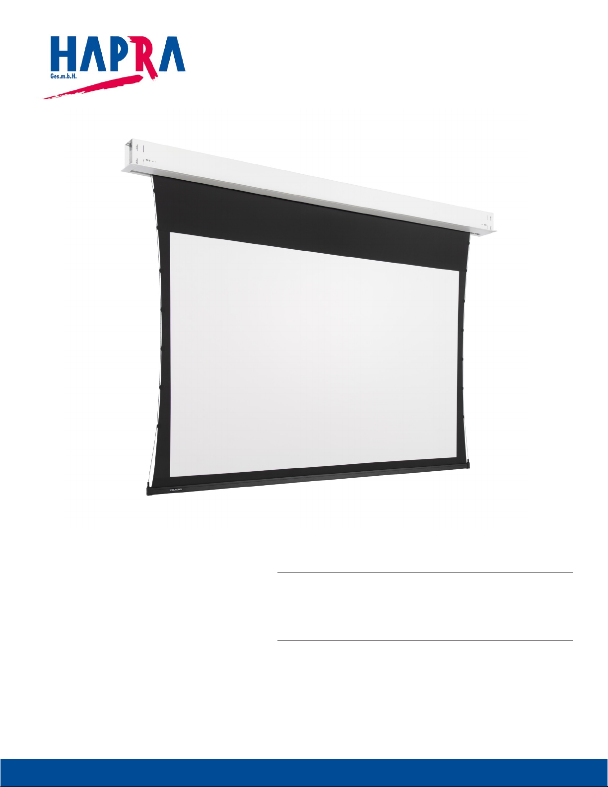
PRÄSENTATIONSTECHNIK
30751167 /05-2018
INSTRUCTION BOOK FOR
DescenderPro
Karl-Leitl-Str. 1 | 4048 Puchenau | T +43 732 70 04 25 | F +43 732 70 04 25-55 | offi[email protected] | www.hapra.at
Page 2
Original Instructions
L1
Disclaimer
Milestone and its ailiated corporations and subsidiaries (collectively "Milestone"), intend to make this manual accurate and complete.
However, Milestone makes no claim that the information contained herein covers all details, conditions or variations, nor does it provide
for every possible contingency in connection with the installation or use of this subject to change without notice or obligation of any
kind. Milestone makes no representation of warranty, expressed or implied, regarding the information contained herein. Milestone
assumes no responsibility for accuracy, completeness or suiciency of the information contained in this document.
Projecta® is a registered trademark of Milestone AV Technologies. All rights reserved.
Important Safety Instructions
When using your video equipment, basic safety precautions
should always be followed, including the following:
1. Read and understand all instructions before using.
2. Maximum surrounding air temperature 50°c.
3. Main disconnect must be incorporated in the ixed wiring in
accordance with the wiring rules.
4. Rated for indoor use only.
5. Use copper rated conductors rated 75°c or higher.
6. If the supply cord is damaged, it must be replaced by the
manufacturer, its service agent or similarly qualiied persons in
order to avoid hazard.
7. Position the cord so that it will not be tripped over, pulled, or
contact hot surfaces.
8. If an extension cord is necessary, a cord with a current rating at
least equal to that of the appliance should be used. Cords rated
for less amperage than the appliance may overheat.
9. To reduce the risk of electric shock, do not disassemble this
appliance. Contact an authorized service dealer when repair
work is required. Incorrect reassembly can cause electric shock
when the appliance is used subsequently.
10. The use of an accessory attachment not recommended by the
manufacturer may cause a risk of ire, electric shock, or injury to
persons.
11. Failure to provide adequate structural strength for this
component can result in serious personal injury or damage to
equipment! It is the installer’s responsibility to make sure the
structure to which this component is attached can support the
weight of all equipment. Reinforce the structure as required
before installing the component.
12. Use this projection screen only for its intended use as described
in these instructions. Do not use attachments not recommended
by the manufacturer.
Save These Instructions
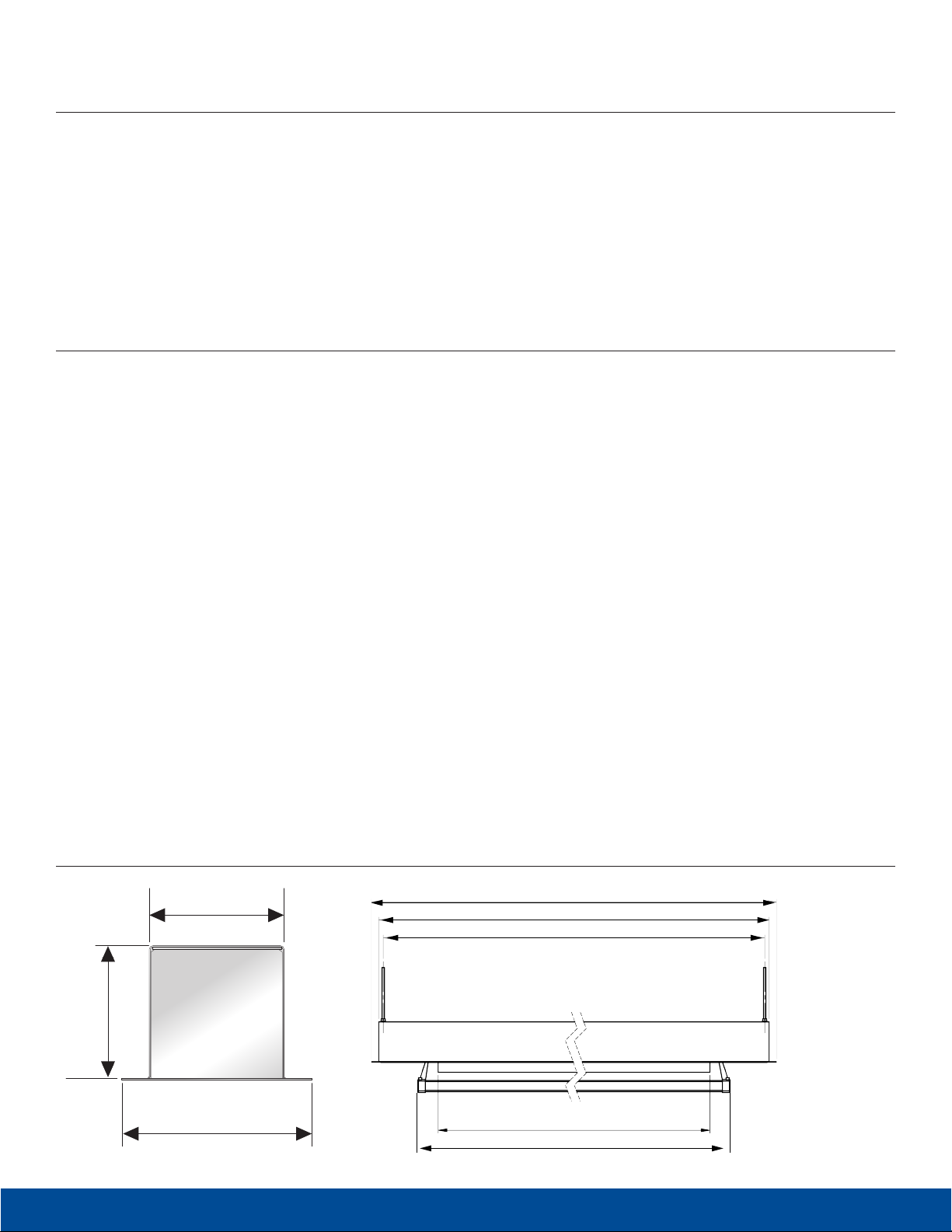
Technical drawing
126
132
174
2
Karl-Leitl-Str. 1 | 4048 Puchenau | T +43 732 70 04 25 | F +43 732 70 04 25-55 | offi[email protected] | www.hapra.at
L2
L3
VAW
L4
Page 3
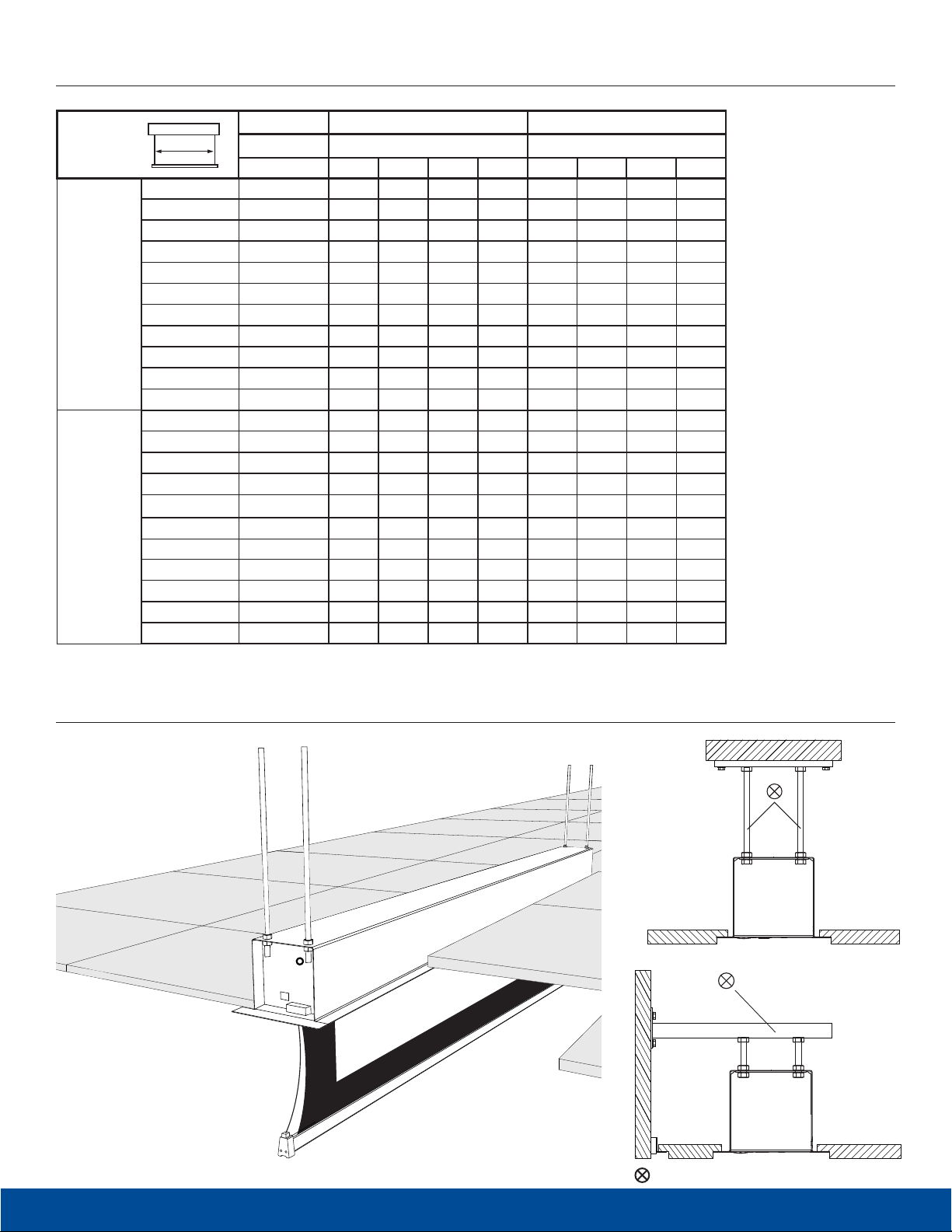
Case dimensions
200
220
240
260
280
16:10
16:9
300
320
340
360
380
400
200
220
240
260
280
300
320
340
360
380
400
Tensioned DescenderPro DescenderPro
Viewing Area Dimensions (mm) Dimensions (mm)
cm L1 L2 L3 L4 L1 L2 L3 L4
119 x 190 2378 2348 2329 2127 2178 2148 2129 2040
131 x 210 2578 2548 2529 2341 2378 2348 2329 2240
144 x 230 2778 2748 2729 2525 2578 2548 2529 2440
156 x 250 2978 2948 2929 2771 2778 2748 2729 2640
169 x 270 3178 3148 3129 2933 2978 2948 2929 2840
181 x 290 3378 3348 3329 3145 3178 3148 3129 3040
194 x 310 3603 3573 3554 3355 3378 3348 3329 3240
206 x 330 3823 3793 3774 3567 3578 3548 3529 3440
219 x 350 3978 3948 3929 3779 3778 3748 3729 3640
231 x 370 4178 4148 4129 3991 3978 3948 3929 3840
244 x 390 4378 4348 4329 4105 4178 4148 4129 4040
107 x 190 2378 2348 2329 2113 2178 2148
118 x 210 2578 2548 2529 2325 2378 2348 2329 2240
129 x 230 2778 2748 2729 2539 2578 2548 2529 2440
141 x 250 2978 2948 2929 2751 2778 2748 2729 2640
152 x 270 3178 3148 3129 2967 2978 2948 2929 2840
163 x 290 3378 3348 3329 3181 3178 3148 3129 3040
174 x 310 3603 3573 3554 3397 3378 3348 3329 3240
186 x 330 3823 3793 3774 3615 3578 3548 3529 3440
197 x 350 3978 3948 3929 3757 3778 3748 3729 3640
208 x 370 4178 4148 4129 3969 3978 3948 3929 3840
219 x 390 4378 4348 4329 4089 4178 4148 4129 4040
2129 2040
Suggested Method of Installation
= Not included
Karl-Leitl-Str. 1 | 4048 Puchenau | T +43 732 70 04 25 | F +43 732 70 04 25-55 | offi[email protected] | www.hapra.at
3
Page 4
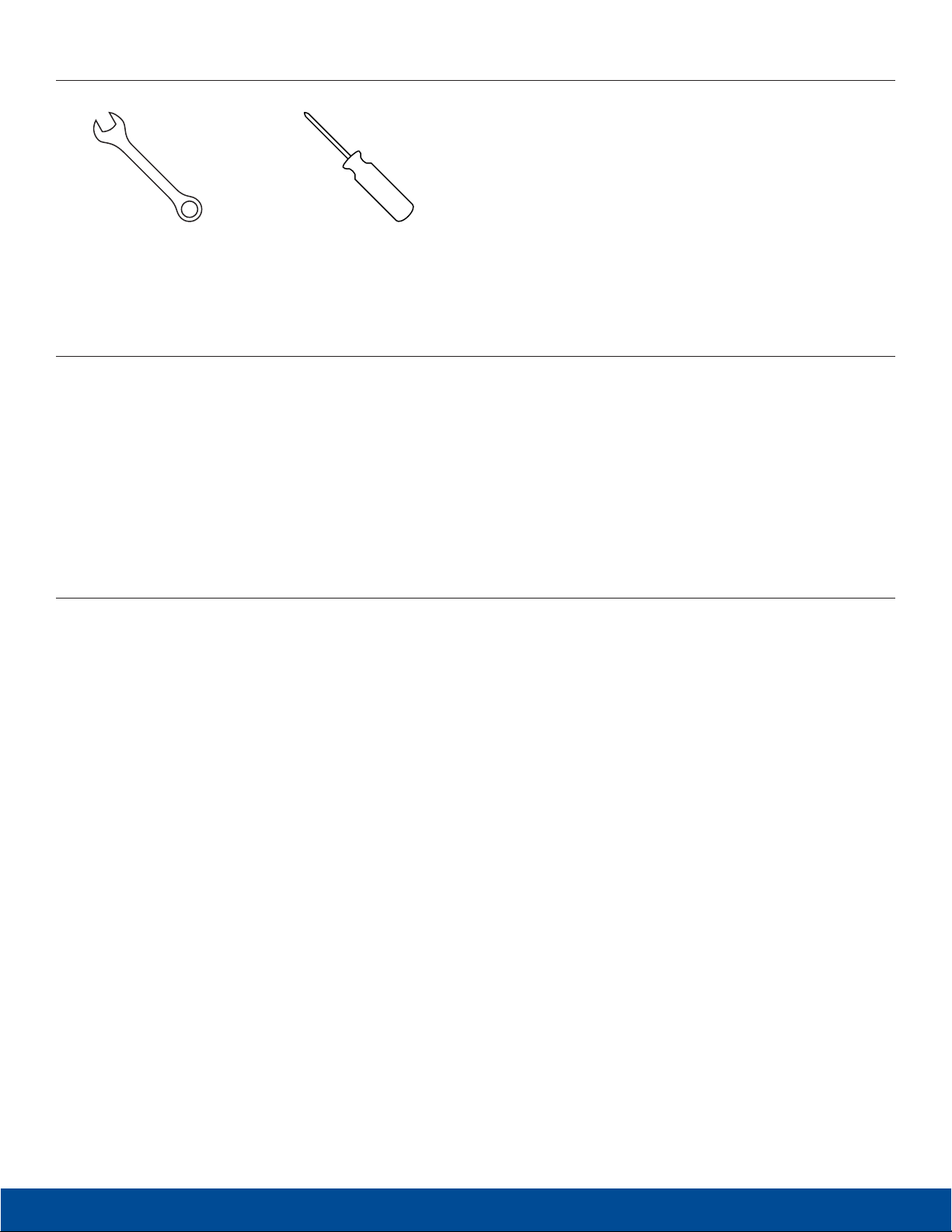
Tools Required for Installation
1/2“ Open Wrench
or Socket Driver
#2 Phillips Screwdriver
Pre-Installation
1. Carefully unpack case from shipping carton.
2. Set aside the Installation Kit. Items inside will be used
during installation.
3. Make sure to recheck measurement of case for proper
installation clearance.
4. Remove any protective foam covering the outside
of the case.
5. Remove the transport safety-brackets that connect the
slatbar to the case.
Prepare your ceiling
1. Determine the required opening in the ceiling by measuring the case.
2. Verify your measurements with the the case dimensions that can be found in the chart on page 3.
Use the L2 dimension and the widht of the case, which is 126 mm
3. Make sure you add 8 mm all around the case dimensions and make the cut-out in the ceiling to enable placement.
4
Karl-Leitl-Str. 1 | 4048 Puchenau | T +43 732 70 04 25 | F +43 732 70 04 25-55 | offi[email protected] | www.hapra.at
Page 5
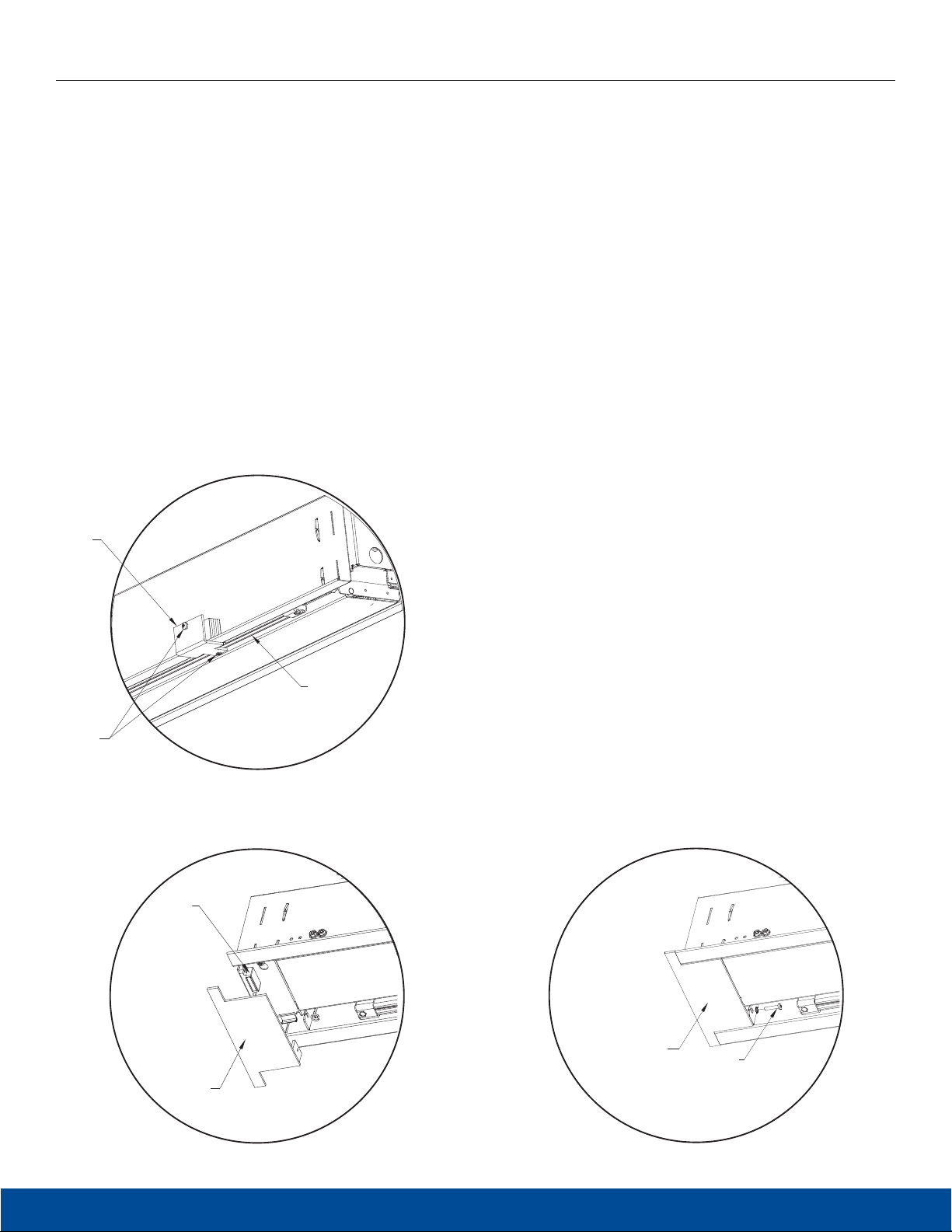
Case Installation
1. Hang case and attach to support structure with threaded
rods and nuts. See Suggested Methods of Installation.
2. Tighten nuts until trim lange is lush with ceiling.
NOTE: For proper operation, case must be levelled side to
side and front to back.
3. If screen surface is tab-tensioned, use a #2 Phillips
screwdriver to remove white transport safety brackets
attached to slat and screen (Figure 1).
4. Connect the power cable to the Easy Install connector on the
left side of the case. (See wiring diagram.)
Slat
Bracket
5. Test installation by running screen up and down a few times.
Be prepared to stop screen should any objects obstruct the
movement of the screen. To prevent damage to the motor,
the standard duty cycle is 1 minute on and 3 minutes of.
6. Install inishing trim covers on both ends of the case. Line up
trim cover lush with case. Magnet will hold cover in place
and secure with safety screw #2 Phillips screwdriver through
motor and pin end bracket (Figures 2 and 3).
Remove
Screws
(Tab-Tensioned Screens Only)
Figure 1
Magnet
Trim
Cover
Slat
Trim
Cover
Safety
Screw
Figure 2
Figure 3
Karl-Leitl-Str. 1 | 4048 Puchenau | T +43 732 70 04 25 | F +43 732 70 04 25-55 | offi[email protected] | www.hapra.at
5
Page 6
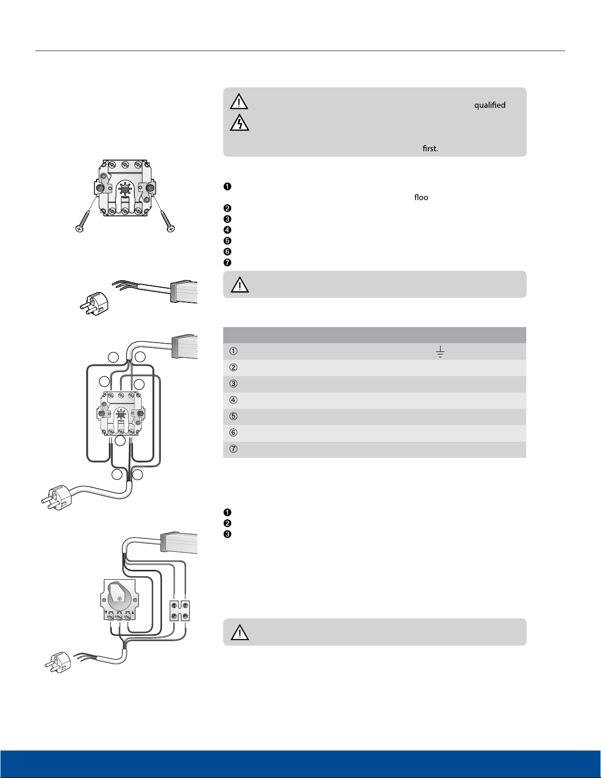
Connecting DescenderPro
1
1
23
23
4
Connecting electrical projection screens
Important!
• The connection of the wiring may only be performed by a
electrician.
• Make sure that the circuits which will be worked on are completely
voltage-free before the electrical connections are made.
• Carefully read section 2 ‘Safety information’
RF Control
1
Wall Switch
2
4
2I L1 1I
2
3
6
2P1
1
Mounting wall switch
First determine the position of the wall switch. Install out of the reach of children
1
and at a minimum height of 1.5 meters from the
Loosen the rotary knob.
r.
Unscrew the nuts under the rotary knob and remove the mechanism from the case.
Mount the mechanism to the wall with two screws.
Connect the wiring as described in § 4.5 / § 4.6.
Place the case and tighten the nuts.
Place the rotary knob.
Important! Only one projection screen can be connected to one wall
switch.
Wiring (general)
Wiring Wall Switch RF Control
7
Yellow / Green4 - Earth
- Earth
Blue 3 - Neutral N - Neutral
5
BrownP - Live - voltage L - Live - voltage
Brown2 - Down
Black 1 - Up
43
Blue 3 - Neutral
Yellow / Green4 - Earth
2
3
A plug may be connected to the feed wire when using the wall switch. The feed wires
may also be connected directly to the electric mains.
Electrical projection screens without built-in RF remote control
Connect the various wires as shown in the diagram.
Key Switch
Replace the case on the wall switch.
Plug the plug into the socket or apply voltage to the circuit concerned again.
In the event of incorrect rotation direction: ensure that the circuit involved is
voltage-free and switch the brown and black motor wires.
Connect key switch
Projection screens wider than 5 meters must always be protected from unauthorised
use. This may be done by using a key operated switch.
Connect the various wires as shown in the diagram.
Important! Only one projection screens can be connected on to one key
switch.
6
Karl-Leitl-Str. 1 | 4048 Puchenau | T +43 732 70 04 25 | F +43 732 70 04 25-55 | offi[email protected] | www.hapra.at
Page 7
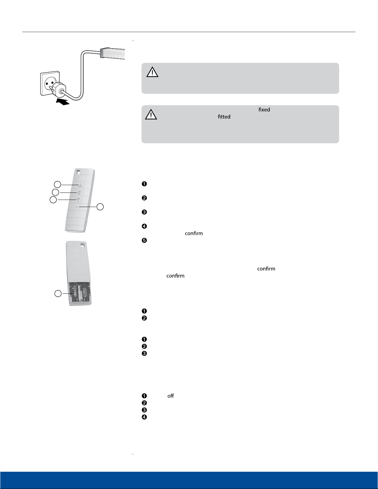
Connecting DescenderPro
1
2
3
4
Electrical projection screens with built-in RF receiver
• Connect a plug (not included) and plug it into the socket.
Warning! Projection screens with a built-in remote control must be
connected to the electric mains using a plug. The plug must be easily
accessible to ensure that the projection screens can be made voltage-free if
necessary.
Warning! If the projection screens has a connection to the electric
mains a switch must be
made voltage-free. This switch must be suitable for use in combination with
the electric mains. The contact opening between the switch points must be
at least 3 mm.
Built-in RF receiver and remote control
Insert the battery
Up button
Allows the projection screen to retract.
Stop button
Stops unrolling/retracting.
Down button
Allows the projection screen to unroll.
LED
Illuminates to
Program button
- Deletes program from remote control.
- Programs new (additional) remote control.
a command.
to ensure that the projection screen can be
When the program button is used, the motor will
beeps will
5
Programming an additional (second) remote control or wall transmitter
Yo u can program an additional RF remote control or wall transmitter for operating
the projection screen.
Press the program button twice (2x) on the original remote control.
Press the program button once (1x) on the extra remote control.
Deleting the program of a remote control
Press the program button once (1x).
Press the stop button once (1x).
Press the program button once (1x).
The program is now deleted.
Programming a new remote control after losing the original
remote control.
Power the motor.
Power on the motor.
Press the program button twice (2x).
Press the down button once (1x).
when a new setting is accepted.
with a ‘beep’. A series of
Karl-Leitl-Str. 1 | 4048 Puchenau | T +43 732 70 04 25 | F +43 732 70 04 25-55 | offi[email protected] | www.hapra.at
7
Page 8
•
•
settings
•
•
•
•
•
•
•
•
•
Instructions for use
General instructions
the use of the projection screen.
The motor has been specially developed for this projection screen and ensures
positions may be set on the motor. This has already been done at the factory.
Only change these settings slightly when absolutely necessary. Changes in
As a result of this special construction, the motor has a limited continuous
duration of operation. For most motors, this duration is approximately
4 minutes. This is long enough to allow the projection screen to unroll and retract
several times. However, if the projection screen is used continuously for too long,
the motor will become hot and the thermal overload cut-out will automatically
automatically. This can take 15 to 30 minutes.
operation so that you can check to make sure that there are no persons or
obstacles under the projection screen.
Make sure that children are not able to play with the equipment involved in the
operation of the projection screen (wall switch, remote control).
Under normal use (once or twice daily) conditions, the life of the motor is at
least 10 years. The motor does not require maintenance.
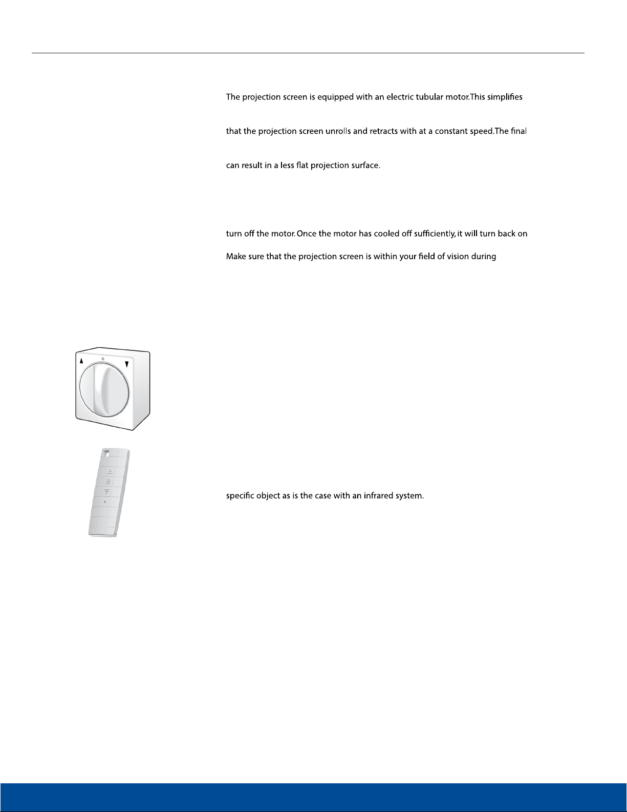
Using the wall switch
Every electrically operated projection screen comes standardly equipped with a
rotary switch for mounting on the wall. After operation, the switch rotates back
to the zero position. This is an additional safety feature to make sure the motor is
always voltage-free when not in use.
Turn the switch to the right to unroll the projection screen and keep the switch
in this position until the projection screen is fully unrolled. Turn the switch to the
left to retract the projection screen.
RF remote control for projection screens with built-in RF receiver
The RF electrol projection screens come standardly equipped with an RF (Radio
Frequency) remote control.
The RF remote control works through walls and does not have to be aimed at a
Two projection screens with RF remote control should not be mounted within
8
30 cm of each other.
Karl-Leitl-Str. 1 | 4048 Puchenau | T +43 732 70 04 25 | F +43 732 70 04 25-55 | offi[email protected] | www.hapra.at
Page 9
Troubleshooting
Symptom Solution
Check for main voltage.
Check to make sure if the plug is plugged into the socket.
The projection screen does not
unroll or retract (anymore).
The projection screen/the
motor made a strange noise the
irst time I used it.
The projection screen motor
is turning in the wrong
direction (reverse direction)
for projection screens without
builtin RF remote control.
The projection screen motor
is turning in the wrong
direction (reverse direction) for
projection screens with built-in
RF remote control.
Check to see if the batteries are installed properly in the remote control.
The thermal overload cut-out of the motor has been activated and has turned o the motor. Wait 15 to 30 minutes
and then try to unroll or retract the projection screen again.
Make sure the projection screen is voltage-free and check the connections as described in section ‘Connecting
DescenderPro’. Check to see if any wires are loose.
It is possible that an object (for example, part of the packaging) fell into the case prior to mounting. Check to see if this
is the case and whether this object is what is causing the noise.
If the motor has been damaged during transport, please contact the supplier.
Consult the connection diagrams in ‘Connecting DescenderPro ’ and switch the brown and black motor wires.
Power o the motor.
Power on the motor.
Press the program button twice (2x).
Press the down button once (1x).
Karl-Leitl-Str. 1 | 4048 Puchenau | T +43 732 70 04 25 | F +43 732 70 04 25-55 | offi[email protected] | www.hapra.at
9
Page 10

LIMITED FIVE YEAR WARRANTY ON PROJECTA DESCENDERPRO PRODUCTS
Goods sold hereunder are covered by a warranty against defects in material and workmanship provided the goods and services are subject
to normal use. The applicable limited warranty is two (2) years from the date the product was invoiced by Milestone. The DescenderPro range,
Elpro Concept range and all electrical motors are covered by ive (5) years limited warranty. All warranties are in eect for the original customer
only.
Milestone disclaims liability for any unauthorized modiication made to the product such as, but not limited to, incorrect voltage connection,
inappropriate limit switch adjustment leading to screen damage, normal wear and tear, discoloration of the projection screen surface resulting
from use in rooms with considerable atmospheric pollution (eg. dust, smoke, humidity and/or corrosive environment). All products are intended
for indoor use only and failure to comply will void warranty.
Milestone will, at its sole option, repair or replace defective products to the original customer under normal use within the warranty period.
Any costs associated with the replacement of the product, outside the product itself are not covered under this warranty. The customer is
responsible for returning the product to Milestone via prepaid shipping.
Milestone will not be responsible for damage to its products caused by misuse, failure to properly package the product for return or for damage
caused by the carriers during shipment to or from Milestone.
Keep your sales receipt to prove the date of purchase and your original ownership.
PRÄSENTATIONSTECHNIK
Karl-Leitl-Str. 1 | 4048 Puchenau | T +43 732 70 04 25 | F +43 732 70 04 25-55 | offi[email protected] | www.hapra.at
 Loading...