


SAO512-6
INSTRUCTION BOOK
Program Ver. *1.34 ~
HCS2
Computerized Compact Single Head Embroidery Machine
Original instructions


-SA -3
INDEX
IMPORTANT SAFETY INSTRUCTIONS.. 1-1
WARNING LABELS & THEIR LOCATIONS .....
1-2
SETTING UP THE MACHINE
Remove the machine from box............... 2-1
Accessories ............................................ 2-2
Assemble machine unit .......................... 2-3
Machine installation ................................ 2-4
Grounding instruction ............................. 2-6
Disposal of a battery............................... 2-6
MAIN PARTS ............................................ 3-1
HOW TO READ THESE INSTRUCTIONS and SCROLLBAR
3-3
MESSAGE ................................................ 3-4
TURNING THE MACHINE ON
How to turn on the machine.................... 3-5
Calendar and clock setting ..................... 3-7
THE CONTROL BOX................................ 3-8
DRIVE MODE ........................................... 3-9
GUIDE....................................................... 3-D
INSERTING A NEEDLE............................ 4-1
SELECT NEEDLES AND THREADS....... 4-2
BACKING MATERIALS............................. 4-3
BOBBIN WINDING
Winding the bobbin................................. 4-4
Removing the bobbin.............................. 4-5
Inserting the bobbin ................................ 4-5
Adjusting bobbin thread tension ............. 4-5
Inserting the bobbin case ....................... 4-5
THREADING THE MACHINE
How to thread upper thread.................... 4-6
MACHINE SETTINGS............................... 5-1
LOCK STITCHES.....................................5-3b
PREPARATION OF PATTERN DATA
Connecting to a PC ................................ 5-4
Reading embroidery pattern data from
the PC ..........................................................
5-4b
Read embroidery pattern data................ 5-5
Reading pattern data .............................. 5-6
Selection of folders ................................. 5-9
How to select patterns from memory...... 5-A
Erasing patterns from memory ............... 5-B
NEEDLE BAR SELECTION ...................... 5-E
SEWING WITH TUBULAR FRAMES
Installing and removing the frame base.. 6-1
How to hoop ........................................... 6-2
Putting the hoop on the machine............ 6-3
Starting to embroider .............................. 6-4
CAP FRAME (OPTION)
Changing the needle plate...................... 7-1
Installing and removing the cap drive frame...
7-2
Normal cap frame ................................... 7-5
Wide cap frame ...................................... 7-8
Starting to embroider .............................. 7-B
ADJUSTING THE THREAD TENSIONS .. 8-1
ADJUSTING THE LASER POINTER (OPTION)...
8-2
SEWING
What to do if the thread breaks while sewing.
9-1
Stopping and resuming sewing .............. 9-1
Loss of power while embroidering .......... 9-2
Moving the hoop while embroidering and then returning to
the correct location (Position) .......................................
9-3
Moving back to the starting point (Origin)9-3
Going back to the beginning of the design (Top) ....
9-4
Placing the design in the center of the selected
embroidery frame
(Center) ..................................
9-4
Rotating and mirroring designs (Convert) ..
9-5
Starting in the middle of a design (Position)...
9-6
DISPLAYING THE PATTERN IN SETTING MODE.
10-1
PATTERN
Locking pattern data ............................. 11-1
Trace type............................................. 11-2
Export ................................................... 11-3
Renaming patterns ............................... 11-5
Copying pattern data ............................ 11-6
Moving pattern data.............................. 11-7
0_1 N401
0-1

-SA -4
INDEX
0-2
Renaming folders ................................. 11-9
Sort........................................................11-A
Thread break report...............................11-B
Retrieve built-in data from machine...... 11-C
Searching pattern data ......................... 11-D
PATTERN SETTINGS ............................ 12-1
Scaling.................................................. 12-2
Width adjustment.................................. 12-3
Angle .................................................... 12-4
Repeat sewing...................................... 12-5
Auto origin ............................................ 12-7
Offset.................................................... 12-8
Frame out ............................................. 12-D
NEEDLE BAR SELECTION .................... 13-1
Auto setting........................................... 13-2
Thread color ......................................... 13-3
Color change data registration ............. 13-5
Color change data read ........................ 13-6
Repetition of color group setting........... 13-7
READING
Join....................................................... 14-1
Pattern Read Settings .......................... 14-4
POSITION ALIGNMENT BY DEFINING 2 POINTS.
15-1
POSITION ............................................... 16-1
Piece number ....................................... 16-2
REGISTER.............................................. 17-1
Entry ..................................................... 17-2
Return................................................... 17-3
LETTER .................................................. 18-1
QUEUE ................................................... 19-1
Alter and Execution .............................. 19-2
Needle bar selection and Pattern settings...
19-4
Registration of QUEUE setting............. 19-5
Read QUEUE setting............................ 19-6
FRAME CONFIRMATION....................... 20-1
Frame selection...........................................
20-2
Adjusted for embroidery area ............... 20-4
User-defined frames (1 ~ 5).................. 20-7
User-defined frames (6 ~ 20).................20-A
How to change center point of frame (1 ~ 5, 6 ~ 20) ..
20-J
Non registered ....................................... 20-L
i-CUSTOM............................................... 21-1
USER MANAGEMENT
Registration of administrator................. 21-3
Registration of user .............................. 21-6
Selection of user (Login)....................... 21-8
Selection of user (Login) at power ON . 21-9
OTHER SETTINGS
Create network ..................................... 22-1
Version information............................... 22-3
Language............................................. 22-3b
Calibrate .............................................. 22-3c
Report................................................... 22-4
User maintenance mode ...................... 22-5
SCREEN SAVER.................................... 22-7
SPECIFICATIONS • MAINTENANCE
Specifications ....................................... 23-1
Oiling .................................................... 23-1
Cleaning of rotary hook ........................ 23-2
Cleaning of thread cutting knife (Rev. A).....
23-2
Cleaning of thread cutting knife (Before Rev. A).
23-4
ERRORS AND WHAT TO DO ................ 24-1
INITIALIZING OF MACHINE SETTINGS
Re-Initialization of machine system ...... 25-1
Initializing of machine speed ................ 25-2
HELPFUL HINTS .................................... 26-1
EMBROIDERY TERMS .......................... 26-2
BUILT-IN FONT LIST.............................. 26-3
BUILT-IN PATTERNS LIST .................... 26-4
0_2 O212

-CS -3
IMPORTANT SAFETY INSTRUCTIONS
1_1 F201
1-1
When using an electrical appliance, basic safety precautions should always be followed, including the following.
Read all instructions before using this appliance.
DANGER - To reduce the risk of electric shock:
1. An appliance should never be left unattended when plugged in. Always unplug this appliance
from the electric outlet immediately after using and before cleaning.
WARNING
- To reduce the risk of burns, fire, electric shock, or injury to persons:
1. Do not allow to be used as a toy. Close attention is necessary when this appliance is used
by or near children.
2. Use this appliance only for its intended use as described in this manual. Use only attachments recommended by the manufacturer as contained in this manual.
3. Never operate this appliance if it has a damaged cord or plug, if it is not working properly, if it
has been dropped or damaged, or dropped into water. Return the appliance to the nearest
authorized dealer or service center for examination, repair, electrical or mechanical adjustment.
4. Never operate the appliance with any air openings blocked. Keep ventilation openings of the
sewing machine and foot controller free from the accumulation of lint, dust, and loose cloth.
5. Never drop or insert any object into any opening.
6. Do not use outdoors.
7. Do not operate where aerosol (spray) products are being used or where oxygen is being
administered.
8. To disconnect, turn all controls to the off (“0”) position, then remove plug from outlet.
9. Do not unplug by pulling on cord. To unplug, grasp the plug, not the cord.
10.Keep fingers away from all moving parts. Special care is required around the sewing machine needle.
11.Always use the proper needle plate. The wrong plate can cause the needle to break.
12.Do not use bent needles.
13.Do not pull or push fabric while stitching. It may deflect the needle causing it to break.
14.Switch the sewing machine off (“0”) when making any adjustments in the needle area, such
as threading needle, changing needle, threading bobbin, or changing presser foot, etc.
15.Always unplug sewing machine from the electrical outlet when removing covers, lubricating,
or when making any other user servicing adjustments mentioned in the instruction manual.
SA VE THESE INSTRUCTIONS

-S2 -7
WARNING LABELS & THEIR LOCATIONS
1_2 M201
1-2
Trapping hazard
Shut the cover when starting the machine.
Do not put hands in while the machine is running.
Trapping, Puncture, Cut hazard wherever this
label is found
Shock hazard on all electrical components
Injury risk on moving head(s)
Keep hands away from the moving heads while the
machine is running.
Laser beam (Class 1)
Do not stare into the beam.
ES-HMF-5113-0
WARNING
Shut the cover when starting the
machine. Do not put hands in
while the machine is running.
Fear of serious injury.
ES-HMF-5117-0
CAUTION
Keep hands away from the
moving heads while the
machine is running.
Possibility of injury.
CAUTION: Injury risk on frame and carriage
Keep hands away from the drive
frame while the machine is
running.
Catch a finger in the X-carriage.
WARNING: Injury risk warning
for all needles
Keep fingers away from
the needles while
the machine is running.
Laser beam (Class 1)
CAUTION
Do not stare into the beam.
-BD -5
SETTING UP THE MACHINE
2_1 K101
2-1
CAUTION: To prevent accidents.
The machine is quite heavy for one person to carry.
Please use two persons when unpacking or carrying.
CAUTION: To avoid problems.
Make sure to hold bottom of the machine body when
removing from the box.
Do not hold any other place. (bed, moving head,
control box etc.).
We recommend unpacking should be done where it has enough room.
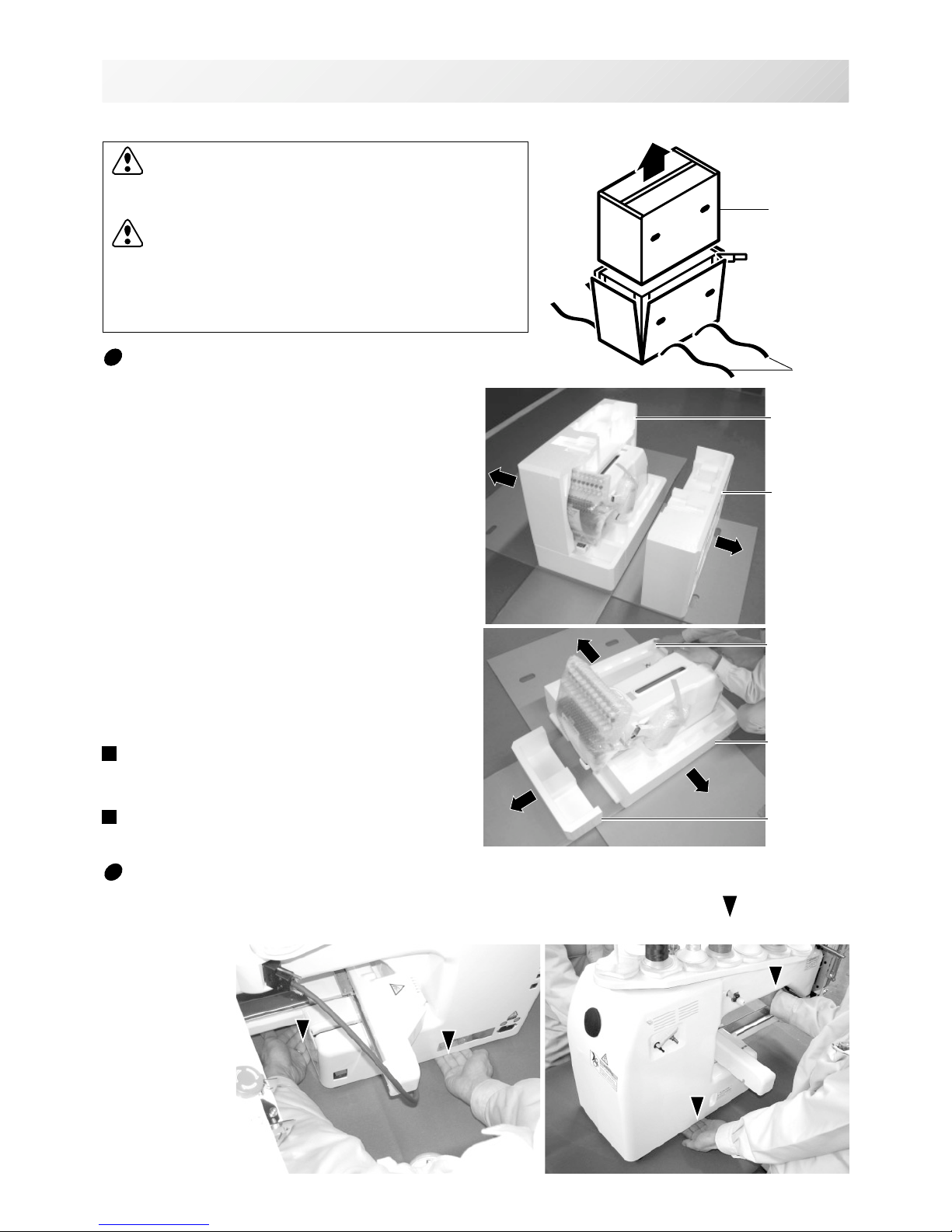
Remove the machine from box
1. Remove 2 straps from the carton.
2. Lift the box (upper) to remove.
3. Take out the accessories.
Refer to the next page.
4. Take out the styrene foam (right) and (left).
5. Take out the styrene foam (lower front),
(lower right), and (lower left).
Be careful not fall down the machine, tilt the
machine slightly when taking out the styrene
form (lower right) and (lower left).
6. Carry the machine to installation location.
Please keep those packing materials in
case of necessary for repair or other reasons.
Packing procedure is the reverse from
unpacking procedure.
Straps
Box (upper)
Styrene foam
(lower front)
Styrene foam
(lower right)
Styrene foam
(lower left)
How to carry machine
The unpacked machine should be carried by 2 person with the hand position at mark shown
in photos.
Right side
Left side
The person holding
the machine from
left side need to
hold the machine
arm by right hand.
Styrene
foam (lright)
Styrene
foam (left)

-S2 -7
SETTING UP THE MACHINE
2_1b M628
2-1b
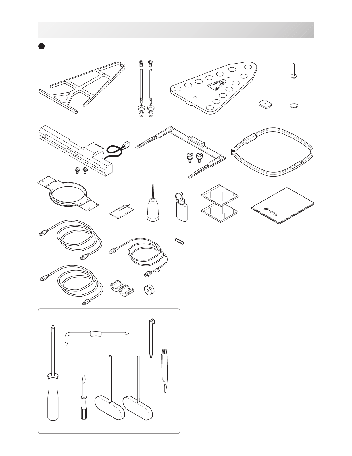
Placement of Accessories
Confirm all the accessories are contained when unpacking.
Frame base
CD-ROM (Instruction manual, Parts list)
CD-ROM (Happy Link Software)
Instruction manual
Embroidery frame (Round)
Embroidery frame (Square)
Thread stand
Thread guide bracket
Carriage
Thread stand felt (13 pcs)
LAN cable
USB cable
Power line cord ass'y
Tool set
Needle (10 pieces)
Fuse (6A)
Oiler
Sewing machine oil
Thread guide pillar (2 pcs)
Thread stand pin (13 pcs)
Wave washer (13 pcs)
A
-S2 -8
18
19
SETTING UP THE MACHINE
Accessories
Please confirm you have received the following.
2_2 N909
2-2
1. Thread guide bracket
2. Thread guide pillar (2 pcs)
3. Thread stand
4. Thread stand felt (13 pcs)
5. Thread stand pin (13 pcs)
6. Wave washer (13 pcs)
7. Carriage
8. Frame base
9. Embroidery frame (square) PTA-32320-360
10. Embroidery frame (Round)
PTA-15-360
11. Needle (DB X K5) (10 pcs)
12. Oiler
13. Sewing machine oil
14. CD-ROM (Happy Link)
15. CD-ROM (Instruction manual, Parts list)
16. Instruction book (How to open the CD-ROM)
17. LAN cable
18. Power line cord ass'y (A shape will be changed
depending on a destination)
19. Fuse (6A)
20. Off set screw driver
21. #2 (+) Screw driver
22. 2 mm (-) Screw driver
23. 3 mm hexagonal driver
24. 2.5 mm hexagonal driver
25. Brush
26. Bobbin (1 pc)
27. Clamp filter
28. Stylus
29. USB cable
T ools
1
2463
7
8
9
11
12 13
15 16
20
21
22
23
24
5
25
14
28
29
17
10
27
3
26

-S2 -9
1
2
3
4
5
6
Assemble machine unit
1. Insert the thread stand pin with wave washer on the
thread stand by turning clockwise, Then insert thread
stand felt.
2. Put the thread stand on to the machine and insert the
thread guide pillar.
(set nut knob nut into the thread guide pillar and 2
washers)
Turn the thread guide pillar clockwise with a 3 mm
hexagonal driver until tight.
Turn the knob nut clockwise with a 3 mm hexagonal
driver until tight.
3. Install the thread guide bracket with supplied screws
(pan head screw M6 x 10 2 pcs).
4. Loosen the screw with a offset driver and remove the
red shipping collars that are equipped on the both side
of the guide bar. (
Keep the shipping collars. It is nec-
essary when packing.)
5. Put the carriage and carriage arm together with screw
(M4 X 8 2 pcs).
2 pins in the upper carriage arm will fit into holes on
the lower carriage.
6. Raise slowly the control box to the front then fix it with
2 supplied screws (M4 1 pcs).
7. Connect the cable of carriage to the machine with
fixed screw.
8. Install the arm for tubular embroidery. Please refer to
(page 6-1) "Installing and removing the frame base".
Or, Install the cap frame for the cap embroidery.
Please refer to (page 7-1) "Installing and removing the
cap drive frame".
9. Insert built-in stylus into the holder (slot) of control
box.
When taking the machine apart in case of packing,
the process is opposite of assembling the machine.
Please do exactly the opposite way of assembling.
When packing the machine up for transportation,
be sure to select the sixth needle and fix it with
shipping collars on the both side of the guide bar.
2_3 N401
2-3
SETTING UP THE MACHINE
7
2
9
-CS -7
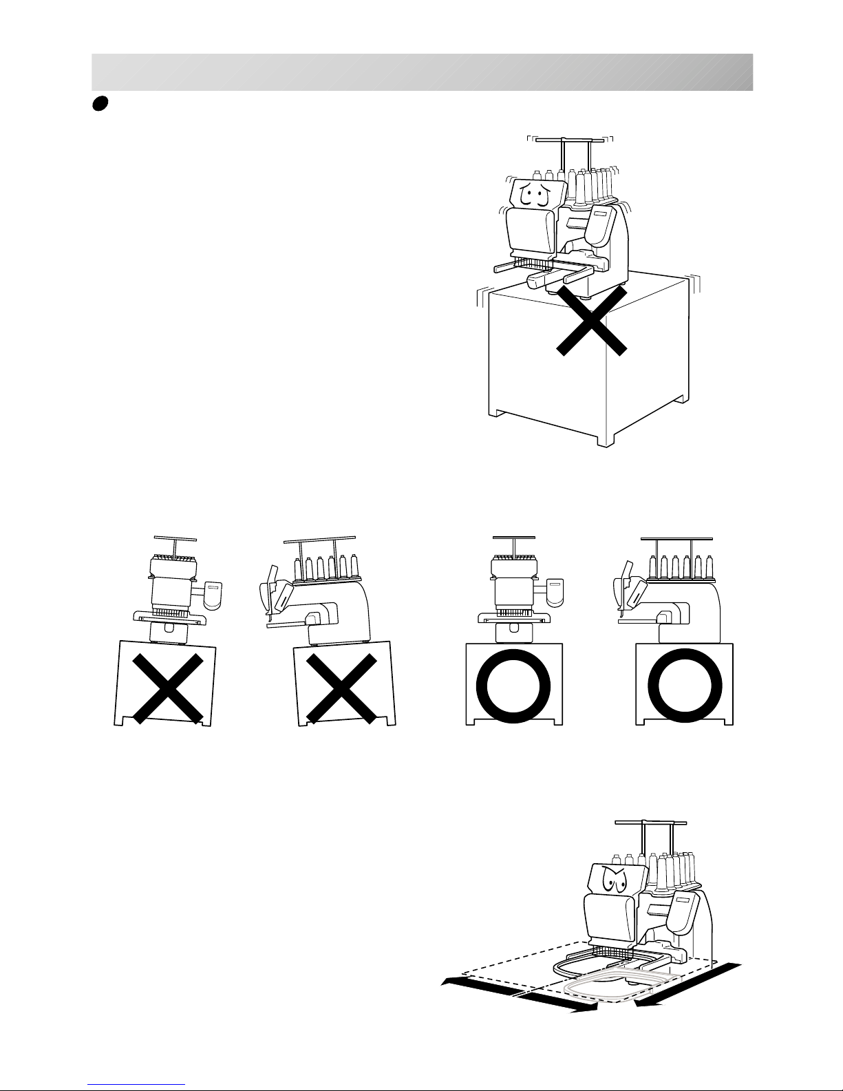
Machine installation
1. Please use a stout table to set the machine
on.
Please check for any shaking or excessive vibrating of the machine table when the machine is
running.
If you have a problem, Please use a stronger
table for the machine.
2_4 D607
2-4
SETTING UP THE MACHINE
350 mm
350 mm
720 mm
2. Please sit the machine level on the table.
3. Please be sure you have this much room
around your machine for it to move.
It is possible for the embroidery frame to hit you
and cause injury.
-CS -82_5 D607
2-5
SETTING UP THE MACHINE
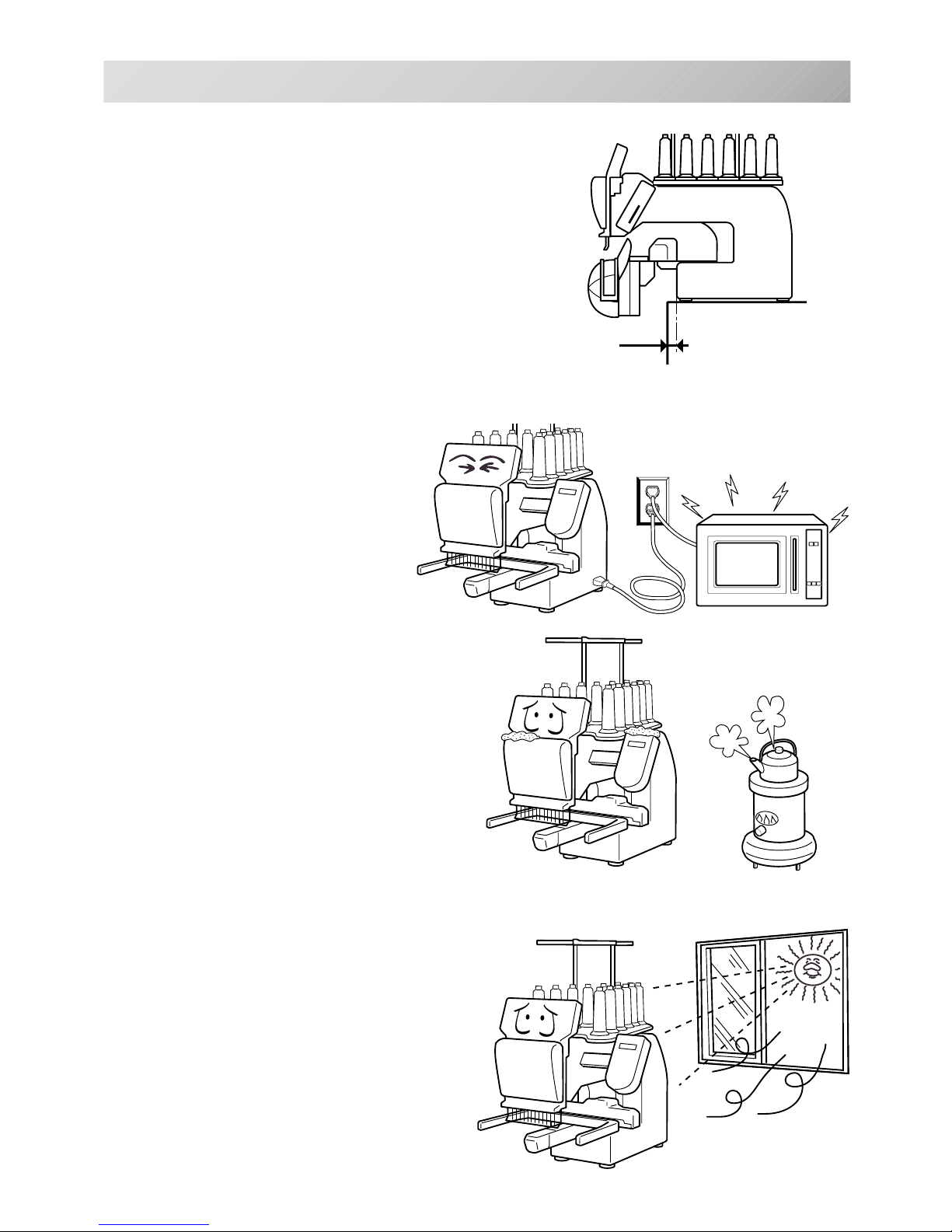
0 ~ 10 mm
4. Please be sure you have this much room around
your cap drive for it to move.
Please machine on the table positioning like right side
drawing.
5. Please do not sit the machine near any
kind of other electric equipment
(Examples: Microwave or electric tool).
Has possible to wrong movement of the
machine.
6. Please keep away from dusty and high moisture environments.
Has case of rusting or damaging.
7. Please do not sit the machine in direct
sunshine or windy locations.
Has case of rusting or damaging.
-CS -11
Grounding instruction (for type of 120V)
This product must be grounded. In the event of malfunction or breakdown, grounding provides a
path of least resistance for electric current to reduce the risk of electric shock. This product is
equipped with a cord having an equipment-grounding conductor and a grounding plug. The plug
must be plugged into an appropriate outlet that is properly installed and grounded in accordance
with all local codes and ordinances.
DANGER – Improper connection of the equipment-grounding conductor can result in a
risk of electric shock. The conductor with insulation having an outer surface that is green with or
without yellow stripes is the equipment-grounding conductor. If repair or replacement of the cord
or plug is necessary, do not connect the equipment-grounding conductor to a live terminal.
Check with a qualified electrician or serviceman if the grounding instructions are not completely
understood, or if in doubt as to whether the product is properly grounded.
Do not modify the plug provided with the product – if it will not fit the outlet, have a proper outlet
installed by a qualified electrician.
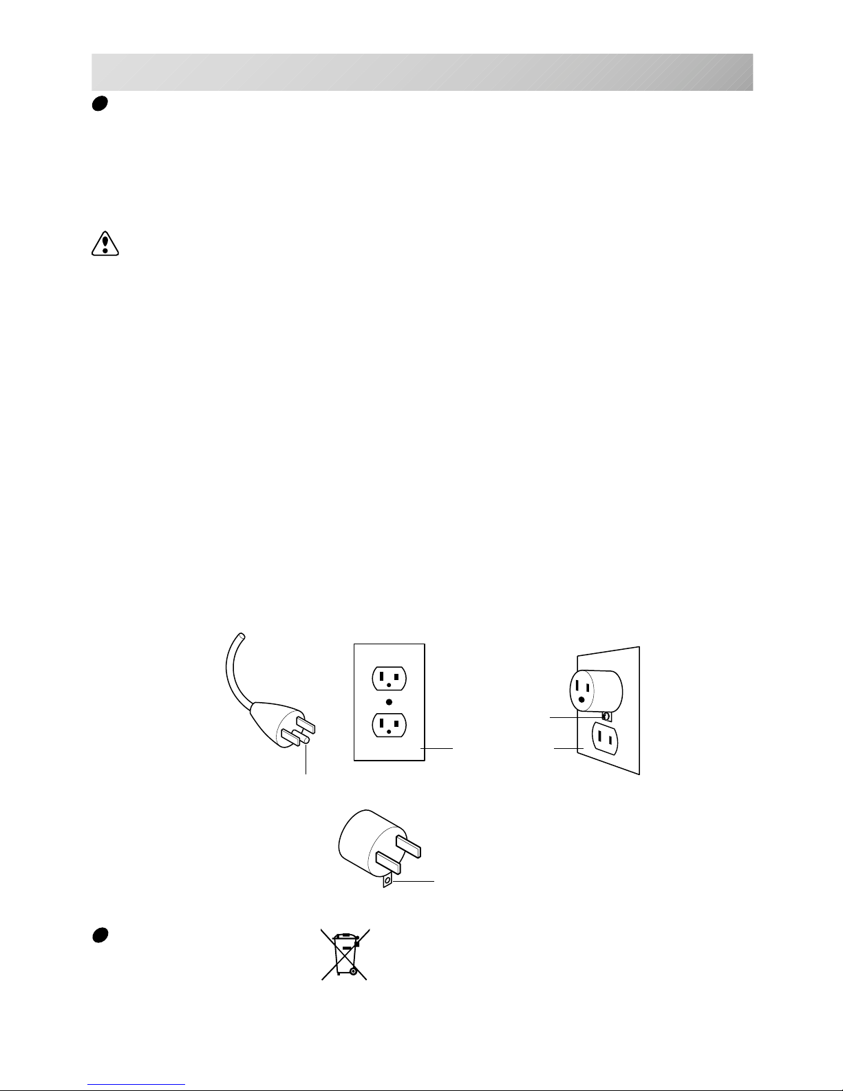
This product is for use on a nominal 120 V circuit, and has a grounding plug that looks like the
plug illustrated in sketch A in Figure. A temporary adaptor, which looks like the adaptor illustrated in sketches B and C, may be used to connect this plug to a 2-pole receptacle as shown in
sketch B if a properly grounded outlet is not available. The temporary adaptor should be used
only until a properly grounded outlet can be installed by a qualified electrician. The green colored rigid ear, lug, and the like, extending from the adaptor must be connected to a permanent
ground such as a properly grounded outlet box cover. Whenever the adaptor is used, it must be
held in place by the metal screw.
2_6 I916
2-6
SETTING UP THE MACHINE
Disposal of a battery
A battery is had built-in to this embroidery machine.
When you dispose of a battery, according to each country or a method determined in each area,
please dispose appropriately.
Metal screw
Cover of grounded
outlet box
Grounding pin
Grounding means
Grounding methods
Adapter
A
B
C
-S2 -10
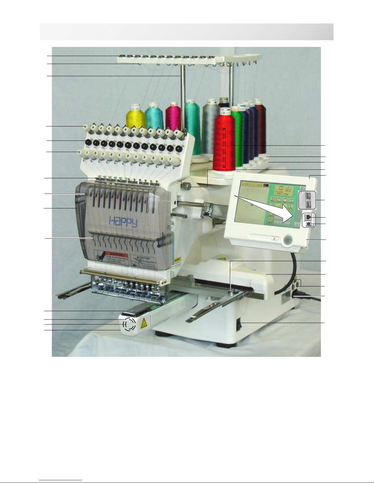
MAIN PARTS
3_1 N909
3-1
1. Hook cover
2. Bobbin case
3. Hook
4. Needle plate
5. Thread check spring
6. Take-up lever cover
7. Take-up lever
8. Lower rectifier
9. Thread tension
10. Detecting roller
11. Minor thread tension
12. Thread guide support
13. Thread guide
14. Upper rectifier
15. Thread stand pin
16. Thread stand felt
17. Thread stand
18. Needle bar selection knob
19. Control box
20. USB port
(Standard-B receptacle)
21. USB port
(Standard-A receptacle)
22. LAN port
23. Frame base
24. Carriage
25. Fuse (6A)
26. Terminal box
27. Power switch
1
2
3
4
5
6
7
8
9
10
11
12
13
15
16
17
18
19
23
24
25
26
27
14
21
16
22
20
-S2 -113_2 M717
3-2
MAIN PARTS
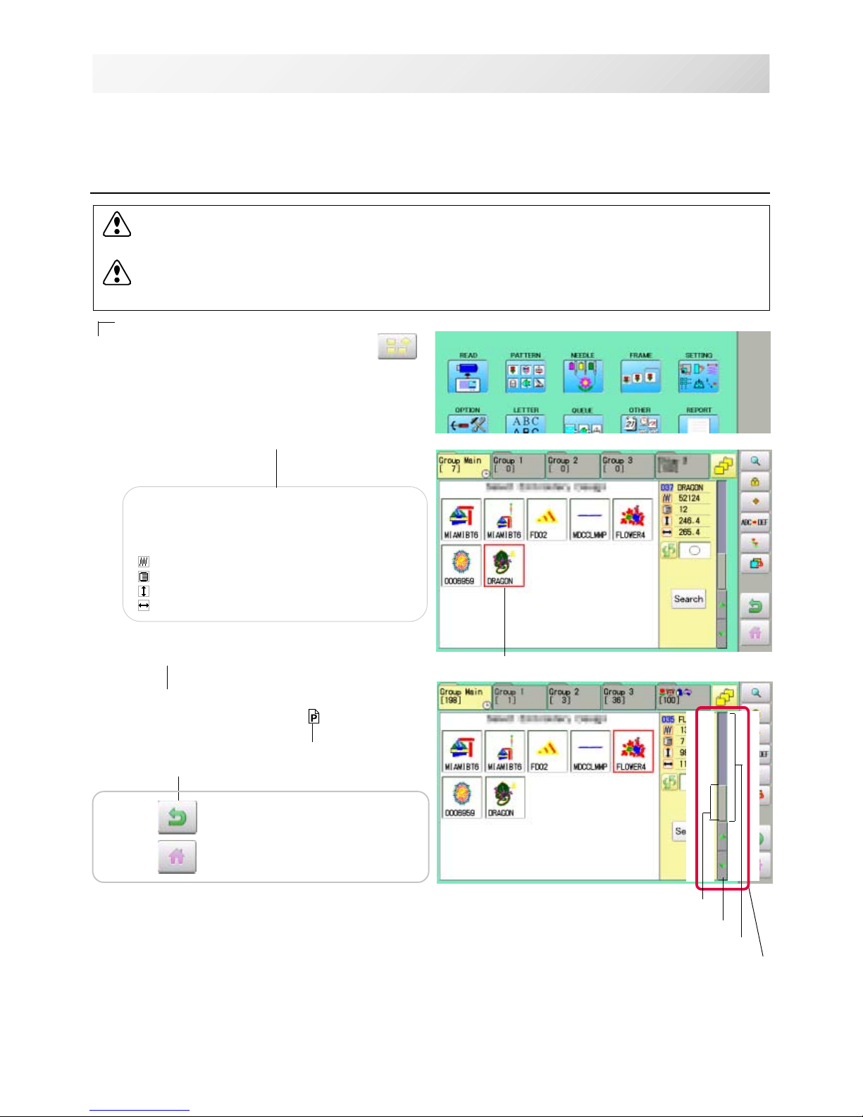
BOBBIN WINDING
7
5
6
1
5
2
3
1. Upper Thread guide
2. Thread stand pin
3. Thread stand felt
4. Thread guide
5. Thread tension
6. Spindle
7. Lever
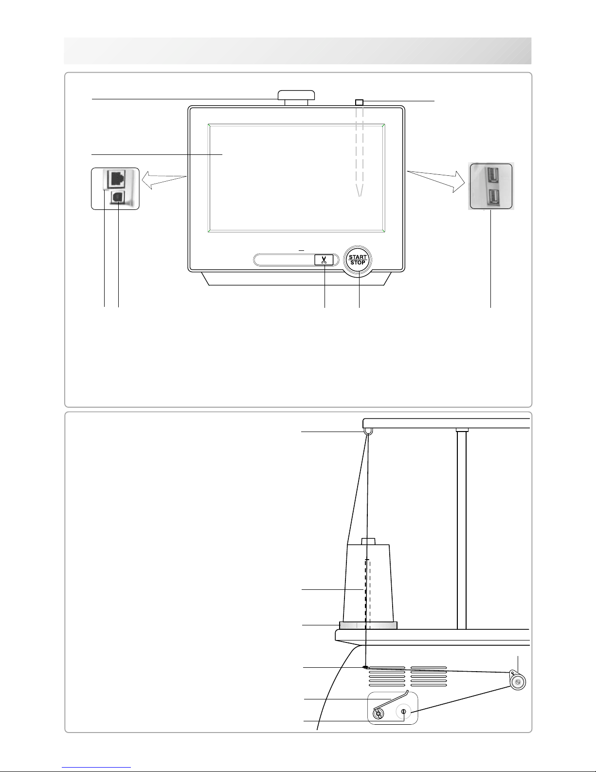
CONTROL BOX
4
5
1. Emergency stop button
2. Display (L.C.D.)
3. LAN port
4. Thread cut button
5. Start/Stop button
6
3
7
1
2
16
8
6. USB port (Standard-A receptacle)
7. USB port (Standard-B receptacle)
8. Stylus
-SA -12
HOW TO READ THESE INSTRUCTIONS and SCROLLBAR
3-3
3_3 NB01
The instructions in this manual have been formatted as follows:
Written instructions will be provided on the left side of the page while graphics depicting the
necessary steps are provided on the right.
Graphics on the far right will show the display after performing the steps indicated.
This indicates an additional
explanation on an operation
elsewhere in the manual for
more detail.
AWords marked with a "*" are explained in
"EMBROIDERY TERMS" at the end of this
instruction manual.
CAUTION: To prevent accidents.
This will appear for items related to your safety.
CAUTION: To avoid problems.
This will appear for items related to potential problems.
Order of operation
Indicates supplementary
explanation regarding a
given operation or action.
1. When the machine is stopped, press .
2. Select "PATTERN".
The display indicates the current pattern.
The left side of display shows the number, name
and details for the current pattern.
Number of stitches
Number of Color change number
Height
Width
3. Select *pattern data.
This pattern will be selected.
3-3
Selected pattern data
Operation key
Press to return to Menu mode.
Press to return to Drive mode.
Scrollbar
Display area
Scroll area
Arrow key
Scrollbar
If the data are too much to fit into display screen, you can use scrollbar.
Display area : It shows the area which is displayed.
Arrow key : You can scroll the display area to arrow marked direction.
Scroll area : It shows the whole area of the data.
You can push arbitrary point of Scroll area to display the desired location.
-SA -16
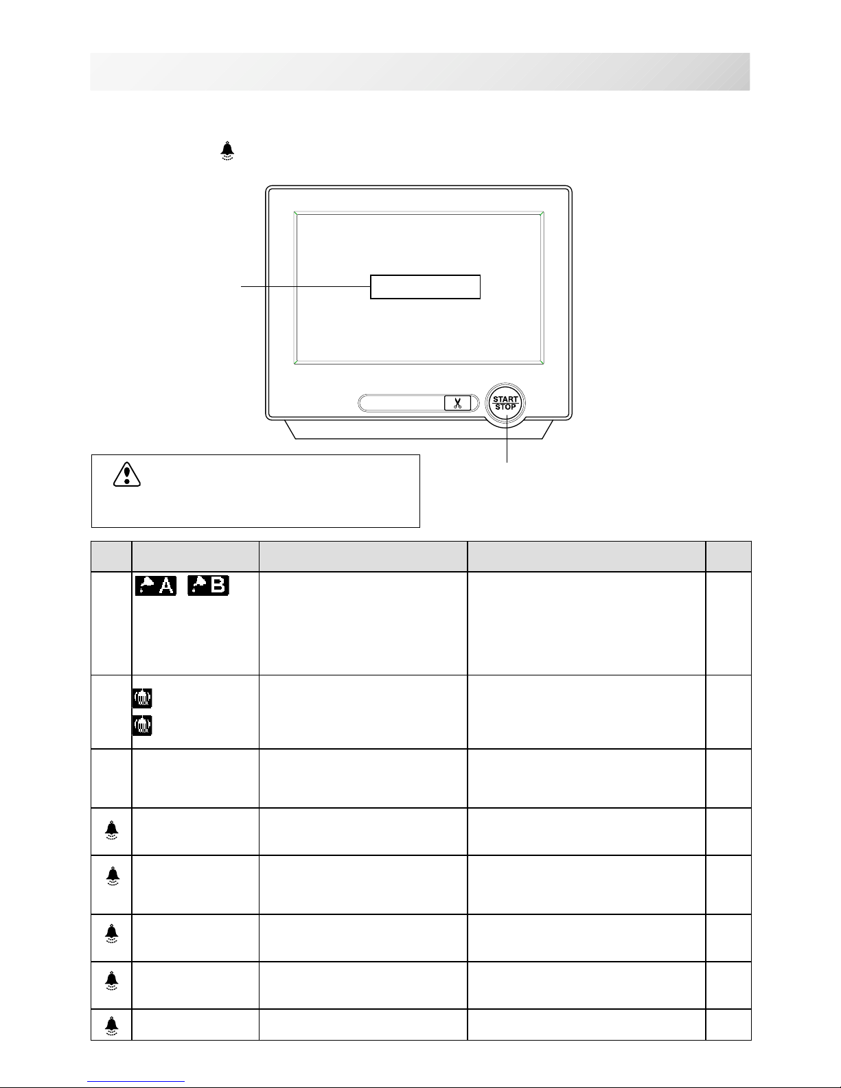
MESSAGES
3-4
3_4 O512
Below is a list of possible messages that may appear while operating the machine, along with
an brief explanation and suggested actions to take as a result.
The message with
mark will be appeared with beep sound.
Press the screen (any location is okay), then message will disappear.
Start/Stop button
Message
>>Stop Switch
CAUTION: To prevent accidents.
The embroidery frame may move. Please
keep hands clear for your safety.
MESSAGE EXPLANATION OPERATION PAGE
Place to oil
Designated letter on the display
is due to be lubricated.
Push [Done] and lubricate indicated
location with instruction in
the reference page.
Push [Leter], if you can not lubricate
right away.
The message will be disappeared
temporary, but it will come up later.
23-1
Cleaning of
rotary fook
Cleaning of
thread cut
knife
Clean the rotary hook and the
thread cutting knife.
Clean with instruction in the
reference page.
23-2
>>Stop Switch
The machine is stopped
because the stop button was
pressed while embroidering the
design.
Press the start/stop button to resume
sewing.
>>End
The machine is stopped
because it has finished the
design.
If you wish to sew design again,
please newly hooped item on
machine & press start/stop button.
>>Change Stop
Machine stopped, because you
used "Stop at color change
point" function.
When you press the start/stop button,
the machine will select the next color
and resume embroidering
automatically.
>>Color ?
Machine stopped because the
next color has not been
selected.
Please select next needle number by
needle selection button then press
the start/stop button.
>>Thread Break
Machine stopped, because
upper or bobbin thread broken.
Please thread upper thread or check
bobbin thread then press start/stop
button to resume sewing.
>>Frame out
The "Frame out" function has
been executed.
Press the start/stop button if OK.
12-D
-SA -14
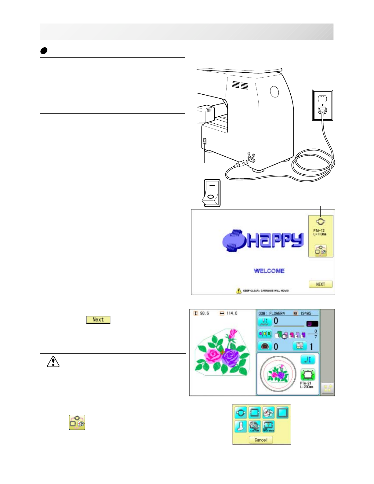
TURNING THE MACHINE ON
1. Connect the power cord to the inlet on the
right side of the machine.
2. Connect the power plug to an electrical
outlet.
3. Turn on the power switch.
Please confirm the emergency stop button has
been released.
Push the power switch firmly so it will remain on.
4. In case you do not need to change frame
type, Press
.
After the carriage and frame move slightly, the
embroidery frame will return to the previous
position automatically.
Machine becomes ready for operation.
3_5 NB25
3-5
ON
OFF
Power switch
CAUTION: To prevent accidents.
The embroidery frame and carriage will move.
Please keep hands clear for your safety.
Selected frame
In case you want to change frame type,
Press
.
CAUTION
The touch screen can be operated by finger,
but in some cases sensitivity of the screen will
be affected by condition of the finger.
In such cases, please use the fingertip or
built-in stylus to hit small touch targets.
How to turn on the machine

-D2 -18
TURNING THE MACHINE ON
3_6 N101
3-6
DANGER: To reduce the risk of electric shock.
Never leave the machine unattended when plugged in.
Always unplug this machine from the electrical outlet immediately after use and before performing any maintenance on it.
WARNING: To reduce the risk of burns, fire, electric shock, or injury to persons.
Do not unplug by pulling on cord. To unplug, grasp the plug, not the cord.
5. Select the desired frame with
.
: Tubular round frame
: Tubular square frame
: Cap and One-point frame.
: Border frame (for HCD2)
: Sock frame
: User-defined frame
: Non registered
6. Select desired type of frame and Press
.
The display returns to the view of Step 3.
To disconnect, switch the power switch to the
off position, then remove plug from outlet.
-D2 -19
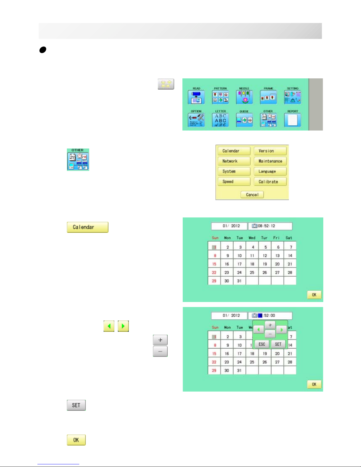
1. When the machine is stopped, press .
2. Press
.
3. Press .
Current year, month date and time is displayed.
4. Select year/month, time or date.
Press right /left of to select the
setting point, and press up/down of
to
select the number of year, month and time.
5. Press
.
The date is fixed.
6. Press to return to Menu mode.
Calendar and clock setting
Setting the calendar and clock lets the machine advise when oiling and other maintenance is
scheduled to occur.
TURNING THE MACHINE ON
3-7
3_6 M620
-D2 -21
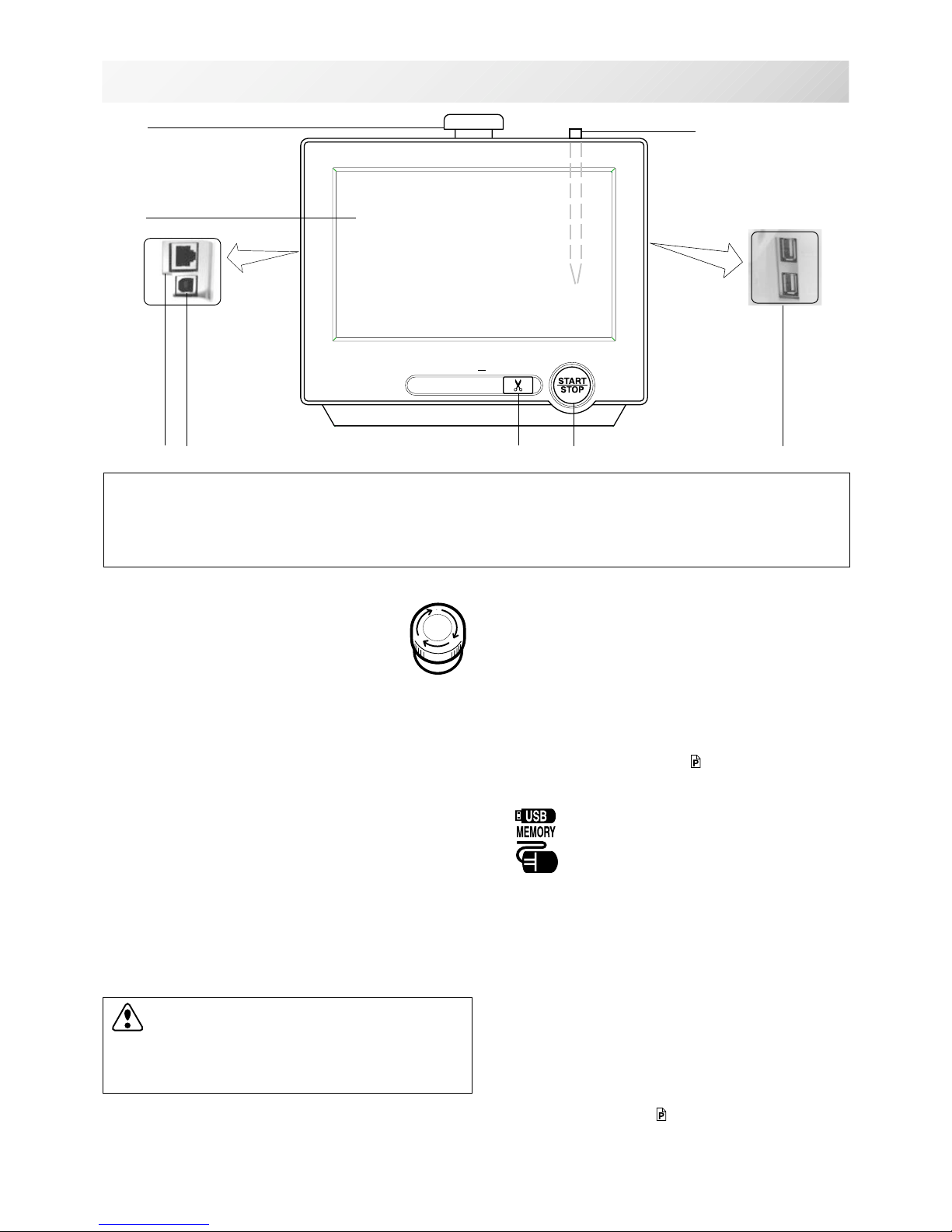
THE CONTROL BOX
3_8 NB25
3-8
5. Start/Stop button
This button starts the machine.
When pressed, while the machine is running, the
machine will stop.
Green ..........Machine ready to sew.
Main menu also accessible by
pressing MENU, which causes menu
to display.
Blinking red .Indicates the upper thread has
broken or the Bobbin thread has run
out.
Red ............. Machine is running.
Orange ........ Machine has detected an error.
An error number will be shown on
the Display. 24-1
6. USB port (Standard-A receptacle)
USB memory socket.
USB mouse socket.
Menu and keys in the display can be operated with
a commercial USB mouse.
Press right mouse button to show a mouse pointer
in the display.
7. USB port (Standard-B receptacle)
Use this port to connect the machine with PC via
USB.
8. Stylus
Stylus can be used for pressing menu and keys in
place of fingers.
Most operation can be done by fingers. Stylus is
required for some operation such as calibration for
the touch panel LCD. 22-3c
Insert a stylus into the holder (slot) of control box
when not used to prevent loss of the stylus.
CAUTION: To prevent accidents.
If you Press thread trim button, the needle will
penetrate the fabric. Please keep your hands
clear for your safety.
1
2
4
5
6
16
1. Emergency stop button
When pressed , the power is switched off
and the machine stops immediately.
The emergency button locks when
pressed.
To unlock, turn the emergency button to
the right
(Arrow direction) then release. The button will
unlock.
Use this button only for emergency.
2. Display (Touch screen)
Shows the embroidery design name, the number of
the current needle and other machine generated
messages.
Menu and keys in the display can be operated with
a finger or built-in stylus.
3. LAN port
You can connect PC with a LAN.
4. Thread trim button
The Machine will cut the upper and lower thread
when this button is pressed.
In case you press and keep (around 2 sec.), you
can cut only bobbin thread.
7
3
8
CAUTION
The touch screen can be operated by finger, but in some cases sensitivity of the screen will
be affected by condition of the finger.
In such cases, please use the fingertip or built-in stylus to hit small touch targets.
-SA -18
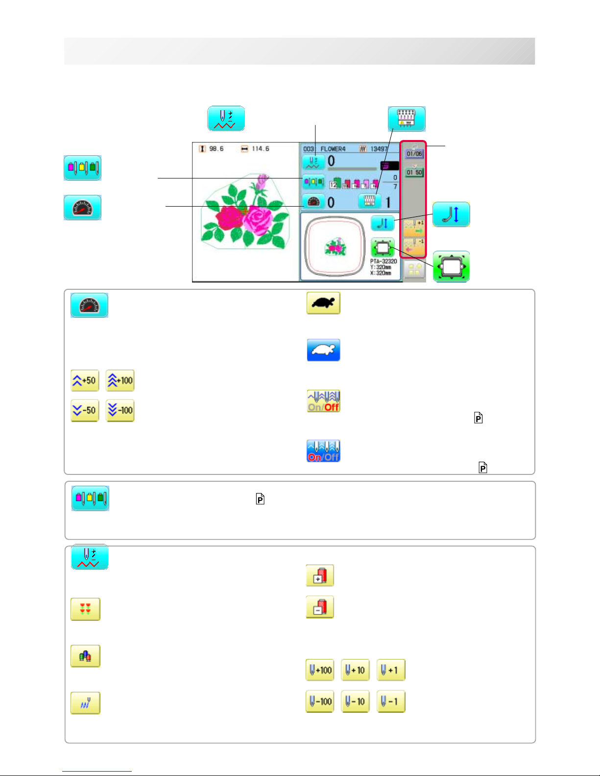
3_9 O512
3-9
DRIVE MODE
Drive key
The each key menu will be shown.
Frame forward
This creates direct designations to the position and
data to the designated sewing position.
Piece
If "Repeat" is set, this allows the frame to move to
the beginning of any piece at will.
Change (Color position )
This moves the frame to the beginning of any Color
change number at will beginning of color.
Stitch (Number of stitches )
This moves the frame to any stitch at will.
Frame forward
Needle bar
selection
Drive speed
Needle change
Frame move
i-Custom
(default display)
Pressure foot
Drive speed
Control embroidery speed.
The speed can be controlled while embroidering.
Speed control
Press the + button to increase the machine sewing
speed and the - button to lower the machine speed.
is displayed on the LCD display.
Low speed operation (OFF state)
Press the button to turn "ON" state.
Low speed operation (ON state)
The drive speed will be reduced to "200 rpm".
Press the button to turn "OFF" state.
Speed setting by needle (OFF state)
Press the button to turn "ON" state. 3-9d
Speed setting by needle (ON state)
Press the button to turn "OFF" state. 3-9d
Needle bar selection 5-E
For each color change in a given pattern, the needle number loaded with the correct color thread is
assigned by the operator.
Color position forward
Move the frame to the beginning embroidery
position of the previous or later color position
number
Stitch number forward
Move the frame forward or backward by the stitch
number displayed in each button.

-SA -193_9b O512
3-9b
DRIVE MODE
Needle change
Change the needle bar directly to the indicated
needle number on the button.
Change
Move the sewing head to the adjacent needle in
the direction of the arrows.
Jump (Off)
The machine can embroider.
Jump (On)
Mchine becomes jump and the machine doesn't
embroider.
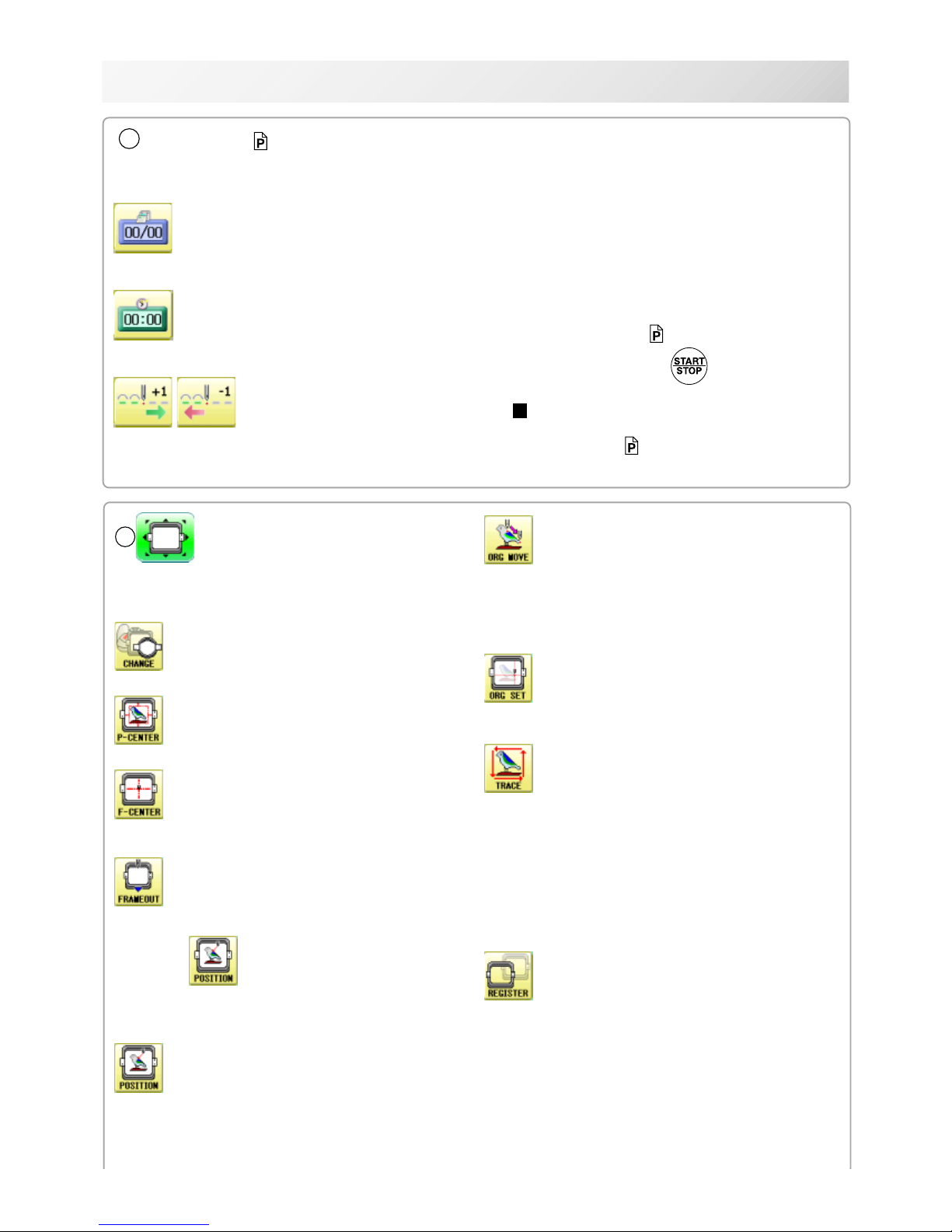
-RA -223_9c O512
3-9c
DRIVE MODE
Original point return
This returns the frame to *pattern origin point.
After performing this action once, repeating this
again will cause the frame to return to the previous
position.
Origin registration
Register the current frame position as origin.
Trace
When pressed while at the beginning of design,
the embroidery frame moves following the outer
edge of the design. This allows you to compare
the design size and position against the frame
before sewing.
Indicate target design on LCD panel when nonshowing design.
If you press this key and hold, re-display your
Register
Register will restore the position of the frame to
the last point before a power failure even if the
point of origin or the pattern itself were changed.
6
Frame move
Selection the way of frame movement and
Move frame.
Frame change
Change the frame to be used.
Design centering
Move design to the center of frame.
Center
Moves the embroidery frame to the center automatically.
Frame out
Move frame to the front position which was set
before.
Press (Position) to return the frame to the
original position before frame out position.
It is convenience if hand work is required in the
middle of embroider process.
Position
When sewing is interrupted in the middle of a
design, this returns the frame to current sewing
position regardless of where frame may have
been moved with the arrow keys after interrupt.
target design.
5
i-Custom 21-1
The following display and key icons are set as default. You can place other frequently used icons freely on
the right side of Drive mode screen.
Calendar
Current year, month date is displayed.
Clock
Current time is displayed.
Stitch number forward
Move the frame forward or backward by the
one
When the key is pressed continuously, the "Key
lock" function is activated and the frame will move
continuously even the finger is released from the
key.
When the key is pressed much longer, the step of
"Stitch number forward" will be changed from one
stitch to 10 stitches. 5-2
When you stop it, press (Start/Stop button).
The "Key lock" and "Fast forward" function will
be activated after setting through ÅgMachine
SettingÅh menu. 5-2
-RA -23
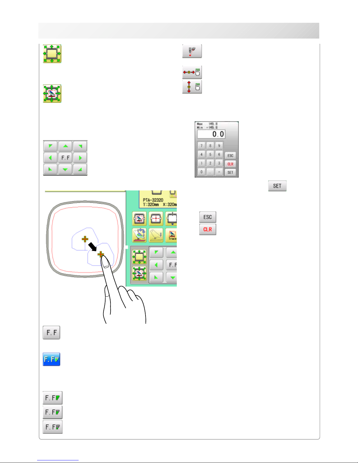
3_9d O512
3-9d
DRIVE MODE
Fast move (OFF state)
Press the button to turn "ON" state.
Fast move (ON state)
Press this key one time to move the frame faster
toward the direction of the arrow.
Press the button to turn "OFF" state.
Fast move speed setting (High)
Fast move speed setting (Middle)
Fast move speed setting (Low)
The speed of "Fast move" can be adjusted.
Pointer (Option)
Turn on and off the laser pointer.
X Direction frame move
YDirection frame move
The frame can be moved with specified distance
along X axis or Y axis. (Unit: mm)
The function allows you to move the frame
precisely with a pitch of 0.1mm.
Select the number, and press .
The frame will move specified distance.
Changing is cancelled.
Numbers are deleted.
Quick move
First press this key and then the arrow key to
move the frame toward the edge of the embroidery area in the direction of the arrow.
Quick embroidery design data position
move
First press this key and then the arrow key to
move the frame where the design data can be
embroidered at
the edge in the direction of the arrow.
Frame move key
The frame moves toward direction of the arrow
mark.
You can move the
embroidery frame by
pressing desired
position on the
screen.
-SA -17
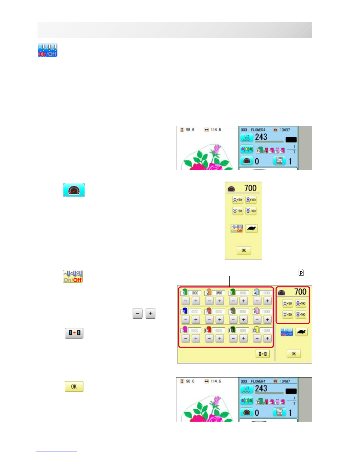
3_9d NB01
3-9e
DRIVE MODE
Speed setting by needle (ON state)
Embroidery speed can be set by needle.
If speed by needle exceeds the speed set at Drive speed setting, the value of speed turns gray
and speed by the needle is applied to the speed set at Drive speed setting.
You can be set up taking the following steps.
1. Press .
2. Press
.
3. Change the setting on the needle number
you would like to change with
.
Press when returning the setting on all the
needle numbers to maximum.
4. Press .
The screen returns to Drive mode.
Speed setting by needle Drive speed setting 3-9
-D2 -25
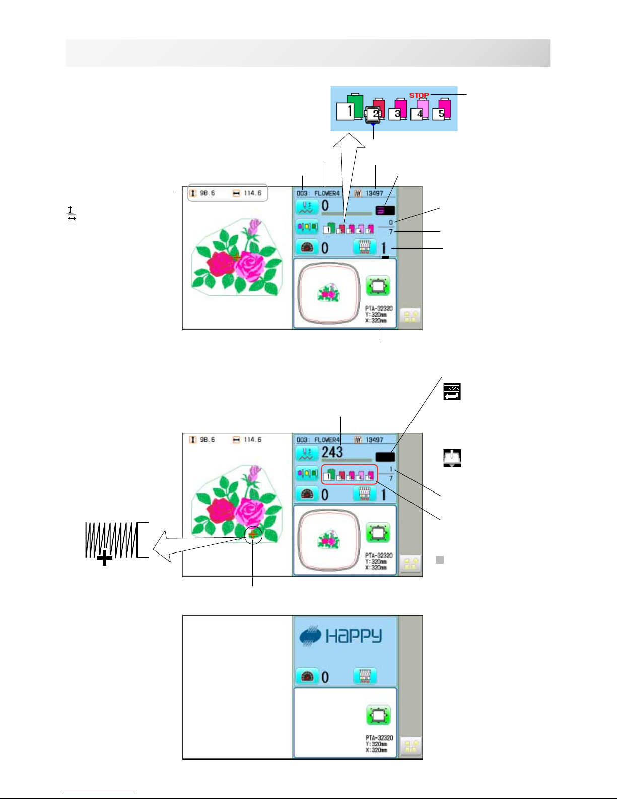
Memory # of selected pattern
Currently-selected
needle
Number of stitches sewn up to now
Name of selected pattern
Top
When beginning an embroidery
Machine stopped during embroidering
Display example
Status
Top
This indicates that the
machine is ready to start
sewing from the "top"
memory position of the
pattern.
Frame out
This indicates that a
frame out is occuring.
3_A NB01
3-A
DRIVE MODE
Pointer
Color change number
sewn up to now
Stitches of pattern
Needle number and color
*Color change number
Pointer indicates the
position of actual stitch
point.
If a needle number is not
assigned to a Color
change number, the
default color will be
assigned automatically.
Shift to left when color
change.
Size of pattern and distance
Heigh
t Width
Current *Color change
number
Mark for color
change stop
Mark for frame out
Selected frame
Display if the machine has no design
in memory
-D2 -26
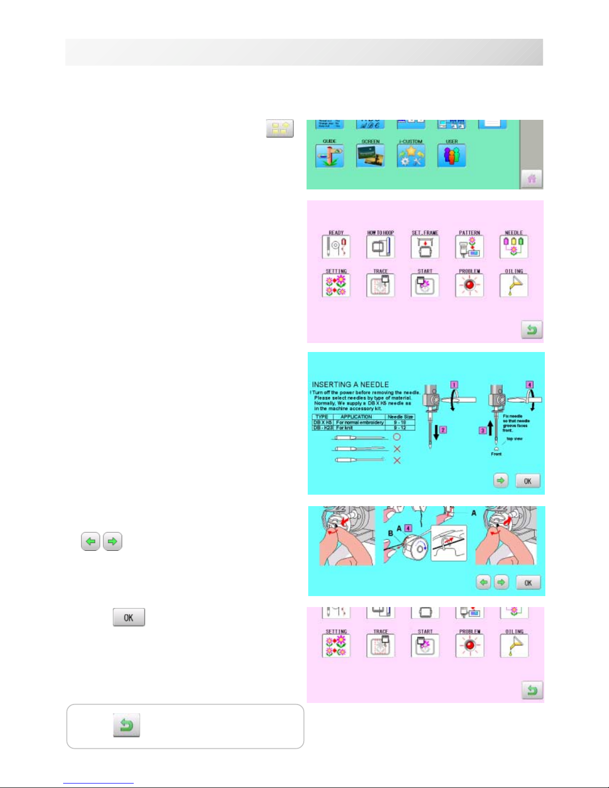
GUIDE
3_D NB01
3-D
1. When the machine is stopped, press .
2. Select "GUIDE".
3. Select desired item.
4. You can move to next page by pressing
.
5. Press .
You will return to the guide menu.
The GUIDE offers tips and step-by-step help for embroidering with the machine.
In each stage of embroidery operation there is an easy to follow guide available.
Press to return to Menu mode.
-CS -19
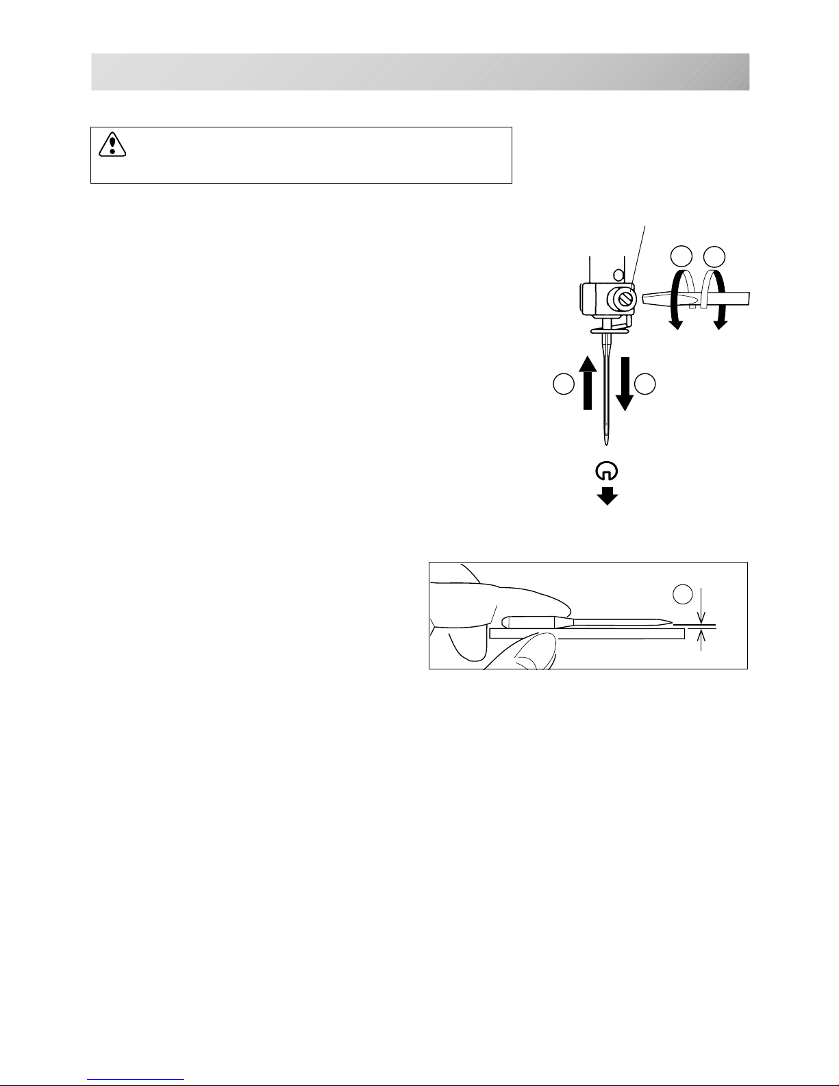
Select a needle of the right type. See the following “SELECT THREADS”.
1
2
4
3
A
4_1 D424
4-1
Needle clamp screw
INSERTING A NEEDLE
Front
T
S
CAUTION: To prevent accidents.
Turn off the power before removing the needle.
1. Loosen the needle clamp screw slightly with the screw-
driver.
2. Remove the needle.
3. Insert a new needle into the needle clamp with push it up
as far as it will go keeping the slotted side of the needle in
front.
4. Tighten the needle clamp screw with the screwdriver.
A. Do not use a bent or blunt needle.
Place the needle on a flat surface and check
for straightness.
-CS -20
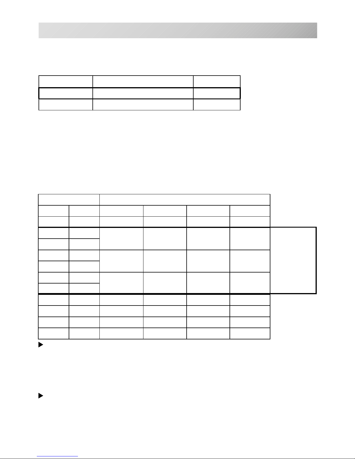
SELECT NEEDLES AND THREADS
About needle
Please select needles by type of material .
Normally, We supply a DB X K5 needle as in the machine accessory kit.
4_2 D607
4-2
Relation of needle and upper thread
Please select type of needle and upper thread by flowing list.
eziSdaerhtreppudnaeldeenfonoitaleR
nagrOnamreG#nottoCkliSretseyloPnoyaR
8#06#031~001061~041002~05107~05
956
08~07021~001051~031001~07
0107
1157
06~05001~08031~001031~001
2108
3158
04~6307~06001~08051~031
4109
5159
6100163~0306~0508~06061~051
71501
8101103~4205~0406~05032~081
Normal embroidery field
Normal use embroidery needle and upper thread.
Upper thread : Rayon 120 d/2 (120 denier)
Polyester 120 d/2 (120 denier)
Needle : #11 ( DB X K5 )
If the relationship of needle size and thread type is incorrect, it is possible to have any of the
following problems.
• Thread break
• Skip stitch (Upper thread does not catch bobbin thread)
• Other stitch quality problem
EPYTNOITACILPPA
eziSeldeeN
32K-BDtinkroF21~9
5KXBDyrediorbmelamronroF81~9

-CS -21
BACKING MATERIALS
Backing
Generally, Backing is used for hooped embroidery fabric. Knit fabrics particularly require the use
of embroidery backings.
Embroidery backings will allow the hoop to move the fabric more accurately, creating a more
beautiful embroidery.
Select backing type
Choose the thickness and number of sheets by the type of material and embroidery condition.
Generally, you should consider the following items.
•Embroidery stitch quality
•Contraction or compression of fabric caused by sewing, etc.
•Stiffness of fabric
In case, if you sew lace and leather, you may not need backing sheet.
Example of using a backing
4_3 D607
4-3
Embroidery frame (Inner frame)
Fabric
Backing sheet
Outer frame

-CS -24
BOBBIN WINDING
Winding the bobbin
4_4 K101
4-4
Thread the bobbin winder as shown below:
1. Upper Thread guide
2. Thread guide
3. Thread tension – Be sure to thread through the
small eye before going between the disks.
4. Bobbin (Place the bobbin on the bobbin winder
spindle.)
5. Press the limit lever as indicated by the arrow
to start the winder. The lever stops the winder
automatically after the winding is complete.
1
2
3
4
5
Increase Decrease
Tension
When adjusting bobbin winder tension:
• Ensure thread winds evenly on bobbin as
shown.
Confirm that the bobbin is wound properly..
• Keep the tension constant while winding.
Tighten thread tension if thread winds too loosely.
CAUTION: To prevent accidents.
When lever is pressed down, the bobbin
winder spindle and the bobbin start turning.
Keep fingers and body away until the bobbin
winder stops turning.

-CD -29
B
A
4_5 K101
4-5
A
B
B
C
B
A
A
BOBBIN WINDING
Removing the bobbin
1. Open hook cover (A) to front.
2. Grasp bobbin case latch (B) and withdraw
bobbin case from hook taking care not to
damage the thread keeper.
Inserting the bobbin case
1. After threading bobbin in case, open bobbin
case latch (A), grasping it in fingers as
shown.
Slip bobbin and case on stud of rotary hook
body, and press in securely. Release bobbin case latch. Press the bobbin case in to
be sure it is fully seated.
2. Close hook cover.
Inserting the bobbin
1. Hold the bobbin case in left hand. Hold the
bobbin in your right hand with thread on top
leading from left to right.
2. Insert bobbin in case and draw thread up
into slot in case.
3. Draw thread under tension spring (A) and
wind into guide coil (B). The bobbin should
turn clockwise in the case when the thread
is pulled.
Adjusting bobbin thread tension
1. Hold bobbin thread and jerk upward approx.
an inch. Thread should unspool further
approx. the same amount.
2. The screw on the tension spring is for adjusting bobbin tension. This adjustment is
very delicate. Please turn the screw only a
small amount. Only 1/8 of a turn maximum.
CAUTION: To prevent accidents.
Please watch out for the point of the rotary
hook when you replace the bobbin.
Increase
Decrease
The attached bobbin case is available only
for this machine. Thread may be caught in
thread guide coil if other types are used.
CAUTION: To
prevent accidents.
Keep hook cover close
and fingers away while
the machine is running.

-CS -24
THREADING THE MACHINE
4_6 AF27
4-6
How to thread upper thread
Pass upper threads in order according to the figure:
1. Thread stand
Set thread cone on the stand.
Small cones can also be used as shown.
2. Thread guide
Thread through the thread guide above each
thread cone.
3. Upper rectifier
Continued next page
2
3
1
Small cone

-CS -25
THREADING THE MACHINE
4_7 D620
4-7
CAUTION: To prevent accidents.
Please be careful of the sharp point of the
needles when threading upper threads
through the needle.
4. Minor thread tension
5. Guide pin upper
6. Detecting roller
7. Guide pin lower
8. Thread tension
Wind upper threads one time around rotary
tension disc clock-wise.
9. Upper thread guide
10.Lower thread guide
11.Lower rectifier
12.Thread guide plate upper
13.Thread adjusting spring
14.Thread guide plate upper
15.Take-up lever
16.Thread guide plate upper
17.Thread guide plate lower
18.Needle bar thread guide
19.Needle
Thread from front side of needle.
Pull upper threads slowly and see that the detecting roller moves smoothly by pulling the thread
downward as much as possible.
20.Thread holding spring
Push thread into spring.
4
6
7
8
9
10
11
15
12,14,16
13
20
17
18
19
5

-SA -23
No. Display
Setting
Difult is underlined
Contents
1 Fine mode
Yes.............
No
...............
The machine emphasizes stitch quality by controlling embroidery speed.
By default it is set to "No".
2 Tightness
level
‑ (Loose)
□
(Normal)
+ (Tight)
The machine adjusts thread tightness level by controlling the timing of frame
move.
By default it is set to "Normal".
3 TRD. break
back
Yes
No
On thread breaks, this causes sewing position & frame to move backwards by
several stitches before the detected break before stopping.
5 Width data
limit
1-13
mm
(13=12.7)
When stitch length exceeds this length, the machine divides it by this jump
length and creates multiple movements. Width data limit becomes 12.7mm only
when setting value is set to 13.
Please use a smaller number when you use thick and heavy material.
6 Quick start
mode
Yes.............
No...............
If you set to "No", the machine will increase speed slowly. Please select "No."
when you have a problem with skipped stitches on the beginning stitch after
thread trim.
• The machine sews up to 3 stitches slowly after thread cut.
• The machine sews up to 5 stitches slowly after thread cut.
7 Auto thread
cut
Yes
No
This performs automatic thread cut after color change and stop.
8 Cut at jump
data
1~8(3
)......
0..................
When a set number of continuous jumps exists in pattern data, the machine
cuts threads before jumping.
• Machine trims the thread on setting number of constant jump.
• Does not trim.
9 Cut at null
jump
Yes
.............
No...............
This sets thread cuts before null jumps (isolated jumps with no net movement)
• Does trim on empty jump data.
• Does not trim on empty jump data.
10 CHG. always
cut
Yes.............
No
...............
Forces a trim at every color change.
• Always thread trim before color change.
• If data does not have trim function at color change point, machine does not
trim.
11 Length of
TRD.cut
Max.
Long
Normal
Short
Min.
Needle........
The machine cuts upper threads to a longer length.
• The upper threads of each needle will be cut off by registered length. 5-2b
13 Width data
all
-1.0 ~ 1.0mm
0.0mm.......
This is to alter the widths of all satin stitches for all the designs in the memory.
• Adjust satin stitch width by selected amount.
• Does not adjust width.
14 TRD. break
detect
Quick 3
~
~
Norma
~
~
Slow 3
Off
Needle........
Sensitivity selection of the thread break detect sensor.
By default it is set to "Normal".
• You can set sensitivity of thread break detection needle by needle. 5-3
15 Convert cap
Yes
No
When you install the cap drive frame on the machine, the machine will convert
(rotate) your design automatically.
16 Revers frame
move
Yes
No
Frame will be moved in the opposite direction of the arrow key.
17 STR.Auto
Position
Yes
No
Machine remembers & returns to last sewn position after sewing interruption
even if operator has moved the frame after interrupt.
18 Embroidery
weight
Light
Middle
Heavy
This setting for heavy duty material depends by material weight.
Normally, please select "middle" or "Heavy" for Border frame.
Machine speed is decreased automatically, when you sellect "middle " or
"heavy".
5-1
MACHINE SETTINGS
5_1 O512
Before embroidering, check the basic settings of the machine.
The rest of the settings can be left at default values (as indicated by underline below).

-RA -32
MACHINE SETTINGS
5-2
5_2 O512
yalpsiD.oN
gnitteS
denilrednusitlufiD
stnetnoC
19 Expand cap
limit
1 ~ 10mm
0mm..........
The direction of Y-axis of the embroidery area (standard) is extended in the
direction of the brim of the cap.
If the embroidery area is extended too much, there is a possibility that a
needle and pressure foot may hit a frame and may be damaged.
Before start sewing, please check carefully the embroidery area by trace
function etc..
• The embroidery area is extended with the set-up size.
• The embroidery area is not extended.
20 Frameout
position
0 ~ 100
~ 780mm
Set movement of frameout in the drive menu.
21 Display inch
Yes
No
• Display the unit of dimensions at an inch.
• Display the unit of dimensions by millimeters meter.
22 Trace speed
0 ~ 100 ~ 300
You can change the Tracing speed. "100" mean the normal speed.
If you change the number bigger, the speed decrease.
23 Display off
timer
0 ~ 240 (min.)
The machine turns off the display screen when the time without any operation
exceeds the time entered in the parameter.
Timer function is "off" when setting value is set to "0"
24 Design disp
mode
All
Change
• When drive mode, highlight all color change number on the LCD Display.
• Highlight only current color change number.
25 Drawing
“ Real
Pattern”
Yes
No
Display pattern with realistic image on the screen.
26 Operation
Sound
Yes
No
Make beep sound when button or key of touch panel is pressed.
27 Notificati-
on Sound
Yes
No
Make beep sound when the machine is stopped.
28 FW/BW Lock
Count(1st.)
0 ~ 100
In "Stitch number forward", set number of stitches until "Key lock" function is
activated
The "Key lock" function will be disabled when the number of stitches is set to
"0".
29 FW/BW Lock
Count(10st.)
0 ~ 100
Set number of stitches until step of “ Stitch number forward” is changed from
one stitch to 10 stitches.
The “ Stitch number forward” function will be disabled when the number of
stitches is set to “ 0” .

-SA -24
MACHINE SETTINGS
5-2a
5_2a O512
1. When the machine is stopped, press .
2. Select "OPTION".
3. Select
.
4. Select desired setting item and change the
setting.
You can move to next page by pressing
.
Press to return to Menu mode.
Press
to return to Drive mode.

-D2 -30
5-2b
MACHINE SETTINGS
5_2b MA05
Detailed explanation of machine settings
11 Length of TRD.cut
If you select "Needle" with this setting, the upper threads of each needle will be cut off by registered length.
The length of each thread can be set up taking the following steps.
1. Follow the steps 1.- 3. on the previous page
and the display shows machine setting
page.
2. Press .
3. Change the setting on the needle number
you would like to change with
.
Press when returning the setting on all the
needle numbers to default.
4. Press .
Needle number
13 Width data all
This function adds additional width to all satin
stitches in a design. 12-3
This is otherwise set in the "Settings" function, in which case any changes made to the setting
from this screen will have no effect.

-D2 -31
5-3
MACHINE SETTINGS
5_3 MA05
Needle number
15 TRD. break detect
If you select "Needle" with this setting, you can set sensitivity of thread break detection needle
by needle.
You can be set up taking the following steps.
1. Follow the steps 1.- 3. on the page 5-2 and
the display shows machine setting page.
2. Press
.
3. Change the setting on the needle number
you would like to change with
.
Press when returning the setting on all the
needle numbers to default.
4. Press .

-SJ -29
LOCK STITCHES
5-3b
5_3b NB01
1. When the machine is stopped, press .
2. Select "OPTION".
3. Select
.
4. Select desired setting item and change the
setting.
Press when returning the setting on all the
needle numbers to default.
SETTING ITEM SETTING RANGE CONTENTS
1 Cut Lock stitch
OFF : Remove lock stitch when the machine cuts threads.
ON : Add lock stitch per SETTING ITEM 2 and 3 when the machine cuts threads.
AUTO : Add lock stitch when length of the stitch before thread cut is longer than length
set at SETTING ITEM 2.
2 Cut Lock Length 0.4~0.5~1.2mm : Set lock stitch length when "ON" or "AUTO" on SETTING ITEM 1 Cut Lock
stitch is selected.
3 Cut Lock Count 1 ~ 2 ~ 3 : Set number of lock stitch when "ON" or "AUTO" on SETTING ITEM 1 Cut Lock
stitch is selected.
4 STR. Lock stitch Add Lock stitch when the machine starts sewing.
OFF : Remove lock stitch when the machine stars.
ON : Add lock stitch per SETTING ITEM 5 and 6.
AUTO : Add lock stitch when length of the stitch before the machine starts sewing cut is
longer than length set at SETTING ITEM 5.
5 STR. Lock Length 0.4~0.5~1.6mm : Set length of lock stitch when "ON" or "AUTO" on SETTING ITEM 4 Cut Lock
stitch is selected.
6 STR. Lock Count 1 ~ 2 : Set number of lock stitch when "ON" or "AUTO" on SETTING ITEM 4 Cut Lock
stitch is selected.
Settings to lock stitches.
Press to return to Menu mode.
Press
to return to Drive mode.

-D2 -34
USB port
5-4
PREPARATION OF PATTERN DATA
5_4 MB29
Connecting to a PC
This embroidery machine will allow you to read design data from a connected PC.
A USB cable or a LAN cable can be used for the connection.
Install the clampfilter
In order to avoid unexpected trouble caused by electric noise, install attached clamp filter on
the embroidery machine side on USB cable or LAN cable.
Install attached clamp filter when also using other cable than attached cable.
1. Please set clampfilter on new cable as
picture.
Clampfilter should be located close to
machine.
Cable should be turned around
clampfilter as picture.
2. Please confirm filter is closed completely.
When the filter is removed, please press
latch (2 positions) on clampfilter by thin
rod.
Clampfilter opens and it can be removed
from cable..
Machine
USB connection (
based on the
USB 1.1, 2.0)
Connect by USB cable between USB port (Standard-B receptacle) of the machine and USB port
of the PC.
When you connect the USB cable, make sure that the machine is powered and set into drive mode, and
that the PC is also turned on.
After recognizing USB in your PC, start-up the "Happy Link".
Please refer to instruction book of "Happy Link" for more precise information.
USB

-D2 -35
Reading embroidery pattern data from the PC
Designs can be transferred to the machine along with some functions by using the “Happy Link
LAN” software.
Please refer to the “Happy Link” or “Happy Link LAN” software manual for instructions.
LAN connection
Connect the LAN cable between the LAN port of the machine and the network of the PC.
Multiple and different type of machines can be connected to a PC which has Happy Link LAN software
installed.
Please refer to instruction book of "Happy Link LAN" for more precise information.
Connect to the Switching
HUB or the Wireless LAN
device.
Please refer to instruction
book of "Happy Link LAN" for
more precise information.
LAN port
PREPARATION OF PATTERN DATA
5-4b
5_4b M620

-D2 -285_5 M201
5-5
PREPARATION OF PATTERN DATA
Read embroidery pattern data
Read the pattern to be embroidered from the memory media.
These types of memory media can be used.
This machine is able to read different kinds of memory media, which are generally used.
•USB memory
If you initialize the memory media with your PC, please proceed with FAT or FAT32 format.
Handling note of memory media.
Do not bend, drop, disassemble, charge or heat the memory media.
Keep away from humidity or direct sunlight.
To insert a USB memory
1. Insert the USB memory all the way into the
USB memory port of the machine (right side
of controller).
2. Read embroidery design data according to
following “Memory card reading” in the next
section.
To remove a USB memory
Please handle USB memory carefully.

-D2 -36
Reading pattern data
This reads pattern data and writes into memory.
When the HAPPY format pattern data with *various function settings are read in memory, various functions such as needle bar selection, pattern data adjustments and etc. will be set automatically. (It is necessary to set “etc.func read”. 14-4)
In addition to memory media, this machine can read pattern data saved in the PC connected
with "Happy Link LAN".
Design folder settings on the "Happy Link LAN" is required before reading pattern data.
Please refer to "Happy Link LAN" System INSTRUCTION MANUAL regarding the settings
method.
The pattern data can be read through the designated folder and sub-folders by accessing from
the machine.
If the Happy or Tajima pattern data has Barudan or ZSK *data. (Tajima file : DSB
[Barudan] or DSZ [ZSK])
The machine can read HAPPY and Tajima pattern data normally when "Auto" is selected at
SETTING RANGE of SETTING ITEM 7 data format of Pattern read settings on page 14-4.
If the machine dose not read pattern data cannot at "Auto", please try with other data format
such as Brd (Barudan) or Zsk (Zsk). The machine might be able to read the data. 14-4
5-6
PREPARATION OF PATTERN DATA
5_6 NB01
1. Insert the USB memory into the machine
as described in "Inserting USB memory”.
2. When the machine is stopped, press .
3. Select "READ".
4. Select
(USB memory) or (Pattern
data in the PC).
Indicates pattern data.
TAP : HAPPY
DST : Tajima
DSB : Tajima (Barudan)
DSZ: Tajima (ZSK)
Folder : Contents of folder will be displayed
when you select this icon.
The designs new ID number in the machines memory.
Free memory
Folder
--- Serch pattern ---
Un-recognized device will be shown with gray color.

-D2 -37
5-7
PREPARATION OF PATTERN DATA
5_7c NB01
5. Select pattern data.
1 % of free memory is equivalent to about
400,000 stitches.
If there are more stitches than remaining space,
you may need to delete some designs to make
room for the new patterns.
Once design is read.
Enable to read other pattern data.
If you wish to read another design, continue to read
other pattern data.
If you press , the display will return to step 3.
Switch the source you would like to extract pattern
data from.
When the screen displays pattern data in
the folder, is displayed.
When
is pressed, the screen moves
off from the current folder.
--- Check pattern data ---
--- Reading ---
Press to return to Menu mode.
Press to return to Drive mode.
The icon allows you to read the all
designs at once which are located in the
currently opened folder or directory.

-D2 -38
5-9
PREPARATION OF PATTERN DATA
5_9 NB01
Selection of folders
The pattern data memory is consist of 20 individual folders.
Select desired folder to choose or input pattern data.
Selected folder
1. When the machine is stopped, press .
2. Select "PATTERN".
The pattern data of the selected folder will
appear on the display.
3. Go on to step 4, if you want to select pattern
from displayed folder.
Press
to select from whole folders.
4. Select desired folder.
The selected folder has been switched.
You cannot switch to the folder without pattern
data.
Selected folder
Press to return to Menu mode.
Press
to return to Drive mode.

-D2 -39
5-A
PREPARATION OF PATTERN DATA
1. When the machine is stopped, press .
2. Select "PATTERN".
The display indicates the current pattern.
The right side of display shows the number,
name and details for the current pattern.
Number of stitches
Number of Color change number
Height
Width
3. Select pattern data.
This pattern will be selected.
5_A NB01
How to select patterns from memory
To select an embroidery design previously stored into the machine memory.
Selected pattern data
Selected pattern data
Press to return to Menu mode.
Press to return to Drive mode.

-D2 -40
5-B
PREPARATION OF PATTERN DATA
5_B NB01
1. When the machine is stopped, press .
2. Select "PATTERN".
3. Press from right submenu.
4. Select desired pattern.
Mark will appear left of the pattern.
Make will be cleared by press it again.
Multiple pattern data can be selected.
: Select all the pattern data
: Cancel pattern data erasing
Erasing patterns from memory
This is to erase an unnecessary design data from the machine memory.
Pattern data cannot be erased if the lock is set.
Mark

-SA -27
5-C
PREPARATION OF PATTERN DATA
5_C O512
5. Press .
6. Push "OK" to delete.
The item will be deleted.
To delete other patterns, repeat steps 3 to 6.
Press “Cancel” to cancel the delete.
The display will return to step 2.
Delete pattern? < 2>
Cancel OK
Showing number of delete design(s)
Press to return to Menu mode.
Press
to return to Drive mode.
Erasing all patterns from memory
This is to erase alldesign data from the machine memory.
Patterndatacanbeerasedifthelockisset.
1. When the machine is stopped, press
.
2. Select "PATTERN" while pressing the
and
3. Press .
The item will be deleted.

-SA -22
1. When the machine is stopped, press .
2. Select "NEEDLE".
The screen of color number 1 selection is displayed.
The current color number is showed in the pattern
data display portion.
3. Select the needle number.
After setting the needle number on color number,
the following color number selection is displayed.
You can also select color number directly.
You can switch color change numbers with
if the color change number has more
than 5.
4. Select the needle number on all the color
change numbers.
Press
to return to Menu mode.
Press
to return to Drive mode.
5-E
NEEDLE BAR SELECTION
5_E NB01
For each color change in a given pattern, the needle number loaded with the correct color
thread is assigned by the operator. When this is set, the machine automatically changes to the
programmed needle when the design reaches that point in the course of sewing the design.
You can not setting "NEEDLE" for selected "LOCK" design.
Please release "LOCK" from design.
11-1
Needle
number
Current color
change number
Needle number
Color change number
Press to on the sub menu to check
the setting.
Number of color
change number

-D2 -44
5-F
NEEDLE BAR SELECTION
5_F MA05
Color change stop mark
Frame out mark
Color change stop function
When a color change stop is set to a color change number, the machine will stop after it
finishes sewing the marked needle number, then following message will be shown:
When you wish to start again, Press (Start/Stop button).
1. Select a color change number and press
.
The mark is displayed on the color change number.
2. Set it to the same on other color change number if necessary.
Selection of color change number
Set Color change number to execute frameout.
A frame out command can be added to a design. By setting frameout to a *Color change
number in a design, you can move the frame to a desired position automatically and stop it
after the machine finishes sewing of that color change number.
When you resume operation, the frame has an automatic return to previous position and you
can continue sewing.
12-D
1. Select a color change number and press
.
The mark is displayed on the color change number.
2. Set it to the same on other color change number if necessary.
When you turn frameout "On" without setting the move distance of frameout, this results in
the same action as color a change stop.
No thread cut after color change
When "no thread cut after color change" is set on a color change number, thread cut is not
done after color
change at the specified color change number and the machine switches to the next color
change number.
"No thread cut after color change" function can be set by combining color change stop or
frame out function.
No thread cut mark

-SA -23
6-1
SEWING WITH TUBULAR FRAMES
6_1 NB01
1. When the machine is stopped, press .
2. Press
.
3. Select or .
: Tubular round frame
: Tubular square frame
: User-defined frame
4. Select desired type of frame.
Installing and removing the frame base
Please attach the frame base to the carriage when you wish to use a tubular embroidering hoop.
Please remove it in the reverse order of
installation.

-SA -24
6-1b
SEWING WITH TUBULAR FRAMES
5. Press button.
6. Move the carriage to the position shown by
press
.
7. Place the frame base on the carriage guide
and tighten the knob bolt on the tubular arm
holder completely.
Move the frame base right or left when it is hard
to tighten the knob bolts.
6_1b NB01
Carriage
Fixing base
Knob bolt
Guide
Frame base
Pushing
against
Press to return to Menu mode.

-CS -51
6-2
SEWING WITH TUBULAR FRAMES
6_2 D610
How to hoop
Inner frame
Cloth
Backing
Outer frame
Please stretch the embroidery cloth in the
directions of the arrow to
smooth the cloth.
Do not stretch the elastic cloth too much.
Please smooth the embroidery cloth while adjusting
tightness of outer frame.
i
Loosen
Tighten

-CS -49
6-3
SEWING WITH TUBULAR FRAMES
6_3 H402
Putting the hoop on the machine
1. Move the frame base to the approximate
center position before inserting the tubular
embroidering frame.
2. Insert the embroidery frame.
Make sure that the holder pins are inserted into
the positioning holes of the frame base on each
side.
Holder
Holder
Embroidering hoop
Positioning hole
Positioning pin
Positioning hole
Positioning pin
Frame base
1
2
CAUTION: To avoid problems.
Please do not hit or
push embroidering hoop
to presser foot.

-S2 -18
6-3b
SEWING WITH TUBULAR FRAMES
6_3b M701
Use TAJIMA made tubular frame
You can use TAJIMA made tubular fame which has the same installation width (space between left and right positioning pin) as HAPPY's frame by changing the position of both left
and right hold springs and left and right hold spring bases.
Follow the procedure below after removing tubular frame.
1. Loosen screws (2 each at both left and right).
2. Move both left and right hold spring bases deep into screws.
3. Move both left and right hold springs forward until the spring touches screws and stops
moving.
4. Tighten screws (2 each at both left and right).
5. Install tubular frame and check if the tip of both left and right hold springs enters receiving
hole on tubular frame.
If the tip dose not enter receiving hole, loosen screw, rotate hold springs left or right so
that the tip can enter the hole, and tighten screw.
Please reverse the procedure above when returning to the position of something before
change has been made.
HAPPY
TAJIMA
Hold spring
Hold spring base
Screws
Positioning pin
1
2
3
455
Receiving hole

-SA -26
6-4
SEWING WITH TUBULAR FRAMES
6_4 NB01
Starting to embroider
1. Press and move the frame to the
original point with the
.
2. Press
.
Press , and the embroidering frame moves
for the design trace. 14-5
Make sure that the pressure foot and needle do
not touch the frame.
Press , and trace is stopped.
Go on to step 4 if you want to start embroidering
without tracing.
3. Press after the trace is completed.
The embroidering frame has moved to the first
stitch point of the pattern.
4. Press .
The embroidery will start.
5. After embroidering your design is complete,
show ">>End" and the machine will stop.
The embroidery frame returns to the original
point automatically if the "Auto origin" function
has been activated.
: Original point
(Start point)
You can confirm outline
trace and the position of
the design.
>>End
Forward only when pressing
Pose
Backward only when pressing
Pressure
foot

-CS -55
7-1
CAP FRAME (OPTION)
7_2 N401
Changing the needle plate
You need to change the needle plate when you
embroider a cap.
1. Remove the set screw (2 pieces) by offset
driver and remove the needle plate.
2. Put the needle plate for cap on the bed and
tighten with the set screw.
3. Loosen the set screw (upper side) of pressure foot and unscrew the set screw (lower
side).
4. Press up the pressure foot and tighten set
screw (upper side) and tighten set screw
(lower side) as it shown in the diagram.
Set screw
Pressure foot
Needle plate for
cap frame
1
2
3
4

-SA -27
7-2
CAP FRAME (OPTION)
Installing and removing the cap drive frame
You need to install the cap drive frame into the carriage when you embroider a cap.
Please remove by reverse order of these step.
CAUTION: To prevent accidents.
The frame moves quickly.
Keep hands away from the frame.
7-2 NB01
2. Turn off the power switch.
3. Hold the arc guide by hand and the rail
bracket has to be faced downward, then
install into the bed as showing picture.
When you hold the cap drive frame assembly, be
sure to hold the arc guide of the cap drive frame
assembly.
If you hold the rail bracket, your fingers will be
pout between the rail bracket and the rail bracket
rotary cylinder and rail bracket can get out of
place.
ON
OFF
Rail bracket
Arc guide
Rotary cylinder
1. Press and Press .
The embroidery frame will move to the center .

-S2 -28
7-3
CAP FRAME (OPTION)
7-3 N909
4. Move the cap drive frame backwards away
from you and rotate the rotary cylinder until
the rail bracket is upward as shown at right.
5. Move the cap drive frame in the direction of
the arrow, adjust right-and-left mount base
to carriage arm and fix them by knob bolts.
6. Fix the rail bracket to fixing base by knob
bolts.
You can move the fixing base right or left when it
is hard to tighten the set screw.
Knob bolt
Mount base
Carriage
Rail bracket
Carriage arm
Fixing baseKnob bolt

-S2 -25
7-4
CAP FRAME (OPTION)
7_4 M424
CAUTION: To prevent accidents.
The frame moves quickly.
Keep hands away from the frame.
7. Turn on the power switch.
Selected frame is indicated.
8. In case required Cap frame is already
selected, please jump to operation no.10.
In case selected frame type is not same as
your requirement, Press
.
9. Select the desired frame.
10.Press
.
The embroidery frame will move to the center
automatically.
ON
OFF
Selected frame

-CS -50
7-5
CAP FRAME (OPTION)
4_5 E201
Adjustment
When you hoop a cap on the cap frame, please
adjust in the following manner:
1. Adjust position of clamp support to the
height of the cap. (Fig. 1)
Adjust the height by removing the inner
screws at left and right.
If you adjust position of clamp support and
shorten distance H, embroidery area will be
reduced in Y direction (depth).
2. Adjust the clamp to fit the clamp support.
(Fig. 2)
Loosen wing nuts at left and right to adjust.
3. Adjust up and down position of the hook
according to the thickness of the cap to
adjust clamp tension. At this moment, the
hook should open and close without feeling
too tight.
(For adjustment, proceed to procedure 5
below).
Use the wing nuts for adjustment. (Fig. 3)
If the hook is extremely tight, it will damage the
cap frame permanently.
4. Put the cap frame without a cap to cap drive
on the machine.
(Please refer to operation 8 "Hooping caps"
on next page for mounting).
At this time, adjust so that guide on cap
drive frame doesn't strike clamp support
and gap is reduced as small as possible.
Remove screws at left and right to adjust.
(Fig. 4)
H (Max.)
H (Min.)
Gap Screw
Cap drive
Toward you
Wing nut
Clamp
Screw
Wing nut
Clamp
support
Clamp
support
Hook
Clamp
support
Guide
Fig. 4
Fig. 2
Fig. 3
Fig. 1
Cramp (Open)
Normal cap frame

-CS -60
Cap stretcher
Cap frame
Notched
portion
Clamp
Fig. 5
Sweatband
Flange
Clamp
Hooping caps
1. Place cap stretcher securely
on a sturdy work bench.
2. As shown in Fig. 5, hold cap
frame with both hands and
place on cap stretcher. By
pushing locking levers at 2
places with fingers, place cap
frame so that center guide of
cap stretcher fits in concave
area of cap frame.
Confirm that the cap frame is securely
placed on cap stretcher.
3. As shown in Fig. 6, open clamp and
keep open to the right.
4. Take the front half of the sweatband out
of the cap and cover the cap stretcher
with the sweatband.
Cover the cap stretcher with the sweatband so that the edge of the sweatband
contacts the flange of the cap frame.
Please place one or two sheets of nonwoven fabric (backing) of standard thickness under unstructured caps.
5. As shown in Fig. 7, pull back part of cap
and hook it temporarily on the hook and
smooth out wrinkles on cap.
At this time, align the center of the cap
to the center mark on the cap frame so
that notched portion of the clamp fits
into the seam of the visor of the cap.
6. Latch the hook, taking care not to
cause wrinkles in the cap.
If you can't get rid of wrinkles on the cap,
adjust the cap frame again according to
"Adjustment" of the previous page.
Center guideConcave
Hook
Seam
Fig. 7
Fig. 6
7-6
CAP FRAME (OPTION)
7_6 E201
Nonwoven fabric
Locking levers

-CS -52
7-7
CAP FRAME (OPTION)
7_7 FA27
Fig. 8
7. Remove the cap frame from the cap
stretcher.
8. As shown in Fig. 8, place the cap frame on
cap the drive frame.
You will have to rotate the brim of the hat to
the side in order to get past the needle
case.
Then, push the holder lever in the 2 places
shown, and place the cap frame on so that
the center guide of the drive frame assembly
fits into the cap frame notch.
Confirm that the frame is firmly seated on the cap
drive frame assembly without any gaps.
If there is a gap between the cap frame or the
cap drive holding lever doesn't go into the hole of
the cap frame, loosen the set screw on the hold
lever for adjustment.
Cap drive
frame
Hold lever
Center guide

-CS -61
7-8
CAP FRAME (OPTION)
7_8 KC10
Adjusting screwCap grip
Hook
Hook
Cap drive frame
High Low
Cap stretcher
Guide
Screw
Loosen
(Thick fabric)
Tighten
(Thin fabric)
Wide cap frame
Adjustment
When you fix cap to cap hold frame, please
adjust in the following manner.
Make sure to do the adjustment of the cap
hold frame. If it is not adjusted properly, it
may cause the deformity, damage of the
cap, damage of the cap hold frame and
break of the cap grip.
After adjusting the cap hold frame, make
sure the cap to be set properly.
1. Adjust the length of the cap grip to suit
the thickness of the fabric. At this moment, hook should open and close
without feeling heavy.
(For the adjustment follow the next page
"Hooping caps" item 1 to 5.)
The adjustment to be done by two
adjusting screws. (Fig. 1)
If the cap grip is loose, even after
hooked the cap is not fixed tightly and
the cap is moving. (Fig. 2)
If the cap grip is too tight, you feel
heavy when it is hooked and the grip
bites into the cap too much. (Fig. 3)
If you feel hook extremely heavy in opening
and closing, there is a case that cap hold
frame will lose its shape or damaged.
2. Adjust the guide position to suit the
height of the cap.
Remove screws at left and right to
adjust. (Fig. 4)
Fig. 4
Fig. 2
Fig. 3
Fig. 1

-CS -63
7-9
CAP FRAME (OPTION)
7_9 KC10
Hold lever
Cap strecher
Cap hold frame
Hold lever
Hooping caps
1. Place cap stretcher securely on
sturdy work bench.
2. As shown in Fig. 1, hold cap
hold frame with both hands and
place on cap stretcher. By
pushing hold lever at 3 places
in arrow marks with fingers,
place cap hold frame so that
center guide of cap stretcher
gets in concave of upper cap
hold frame.
Confirm that cap holder frame is
securely placed on cap stretcher
without gap.
3. As shown in Fig. 2, remove cap
grip and keep open to the left.
4. Take the front half of the
sweatband out of the cap and
cover the cap stretcher with the
sweatband.
Cover the cap stretcher with
the sweatband so that the edge
of the sweatband contacts the
flange of the cap frame.
Please place one or two sheets of
nonwoven fabric (backing) of
standard thickness under unstructured caps.
The length of nonwoven fabric
should be the same as one of
round of cap.
5. Place hook of the cap grips.
At this time, align the center of
the cap to the center mark on
the cap frame so that notched
portion of the clamp fits into the
seam of the visor.
Close hook.
Center guide
Concave
Hook
Cap grip
Seam
Notched portion
Sweatband
Cap grip
Flange
Fig. 2
Fig. 3
Fig. 1
Nonwoven fabric

-CS -63
7-A
CAP FRAME (OPTION)
7_A KC10
Clip
ClipLever for clip
Hold lever
Cap drive
frame
assembly
Center
guide
7. Remove the cap holder frame from the cap
stretcher.
8. As shown in Fig. 5, place the cap holder frame
the cap drive frame assembly.
Push the hold lever in at 3 places as shown by
the marks and place the cap holder frame so
that center guide of the drive frame assembly
gets in the upper cap holder frame.
Confirm that the cap holder frame is firmly attached to
the cap drive frame assembly without any gaps.
If there is a gap between cap holder frame and the
cap drive frame, or hold lever doesn't go into hole on
the cap holder frame well, loosen the set screw on the
lever to adjust.
6. As shown in Fig. 4, tip the cap
stretcher forward.
Clip the back of the cap in two
places by stretching the crease out
as shown by the arrows.
Make the clip lever face the inside.
Fig. 2
Fig. 1

-SA -30
7-B
CAP FRAME (OPTION)
7_B NB01
Embroidery
area
There is a case that the upper part of the cap cannot
be embroidered satisfactory depending on shape of a
cap.
We recommend to change design position or reducing
size of the design.
Refer to the instruction book of "Happy Link" to
reduce the size of the design.
Embroidery area
:Original point (Start point)
Embroidery area (Max. *1)
180mm (Normal cap frame)
360mm (Wide cap frame)
You can confirm the outline
and position of design.
Starting to embroider
1. Press and move the frame to the
original point of pattern data by
.
2. Press .
When you Press , the frame will start
moving for the design trace. 14-5
Make sure that the pressure foot and needle
does not touch the frame.
When you Press , the machine will stop.
Go on to step 4 if you want to start embroidering
without tracing first.
3. Press , the design trace fineished.
The cap frame will return to the original point.
* The actual embroidery
area will be restricted by
the design and shape of
a cap.
Forward only when pressing
Pose
Backward only when pressing
Pressure
foot
67mm (Normal cap frame)
95mm (Wide cap frame)

-D2 -47
7-C
CAP FRAME option
7_C M201
4. Press the .
Embroidery will start.
5. After finishing your design, the display will
show ">>End" and the machine will stop.
The embroidery frame will return to the original
point automatically if the auto origin function has
been activated. 12-7
>>End
:Original point (Start point)

-CS -58
8-1
ADJUSTING THE THREAD TENSIONS
1. With the thread going through the hole of
the pressure foot, pull it out slowly toward
the front.
2. Adjust the Minor thread tension by the first
tension knob and then the second Thread
tension knob.
According to the type of upper thread and cloth.
8_1 E801
First tension
Second tension
Pressure foot
LoosenTighten

-SA -31
8-2
ADJUSTING THE LASER POINTER (OPTION)
8_2 NB01
Laser pointer indicates the needle position.
The beam of laser is coming from right upper side, thus the position of laser pointer can be
changed depending on the height of surface of fabric.
Please adjust then angle of laser pointer depending on thickness of fabric and type of frame
CAUTION: Laser beam (Class 1)
Do not stare into the beam.
1. For switch ON laser pointer, Press
and Press on the submenu.
For switch OFF laser pointer, Press .
2. Press to return to Drive mode, and
press and set a position of moving
head to needle No. 1.
3. Set fabric on the frame, then put white
paper to the position of needle and fix by
Scotch tape.
4. Press
and Press .
5. Press .
6. Press
to cancel "Jump".
7. Press and keep until needle reachs to
the paper and make hole.
CAUTION: To prevent accidents.
The needle will penetrate the fabric.
Please keep your hands clear for your safety.

-SA -32
8-3
8_3 NB01
ADJUSTING THE LASER POINTER (OPTION)
8. Little loose the "Fixing screw for X" and
move the screw head up and down for
adjust red laser mark point to hole on paper.
9. Little loose the "Fixing screw for Y" and
move the screw head up and down for
adjust red laser mark point to holeonpaper.
10. Fix the fixing screw for X and the fixing
screw for Y.
11.Check the hole position on paper and the
point of laser beam, and take paper out.
12.Press
.
13.Press
.
Fixing screw for Y
Y direction
Hole on paper
X direction
Source of laser
Fixing screw for X
Laser beam
Press to return to Drive mode.
14.Press .
CAUTION: To prevent accidents.
The needle will penetrate the fabric.
Please keep your hands clear for your safety.
C point
OK

-D2 -58
9-1
SEWING
9_1 M510
What to do if the thread breaks while sewing
If the thread breaks or runs out while sewing, the machine senses the break, stops, and moves
back several stitches from the break point.
(This prevents open sections in the design when sewing is resumed. See the thread break
section.
5-1)
If the upper thread breaks
Thread the upper thread again.
(Refer to
4-6)
In case bobbin thread breaks
Thread lower thread again.
(See bobbin winding
4-5)
CAUTION: To prevent accidents.
When performing a thread trim, be careful of
the needle which will pierce the fabric.
Example: An unsatisfactory gap between lines
because the machine stopped at a half point in
embroidery and the material shrunk.
Stopping and resuming sewing
Even if you need to turn off the machine in the
middle of embroidering, you will be able to
resume sewing from the stop point after turning
on the machine back on.
If you leave the machine off for too long, the
fabric may distort which will create gaps in
the embroidery design.
To suspend sewing
1. Stop the sewing by pressing the
button.
2. Press the
button.
The needle will go down and trim the thread.
3. Turn off the power switch.
To resume sewing from the last sewn position:
4. Turn on the power switch.
5. Press the button.
After the carriage and frame move slightly, the
embroidery frame will return to the previous
position automatically.
6. Press the and back up several
stitches from the stop point by pressing the
3-4 times.
7. Press the
.
8. Start sewing again by pressing the
.
ON
OFF
ON
OFF
>>Stop Switch
CAUTION: To prevent accidents.
The frame moves quickly.
Keep your hands and body clear of the machine.

-D2 -54
9-2
SEWING
9_2 M201
Loss of power while embroidering
If you have a power failure while embroidering, follow these instructions and you can restore the
position of the frame and the pattern data to its state before the failure.
1. Turn on the power switch.
2. Press the
.
3. Press the
.
4. Press the .
The main shaft will make one rotation and stop at
the "C" point (proper stop position).
5. Press the
.
The needle will go down and trim the thread.
6. Press the .
After the carriage and frame move slightly, the
embroidery frame will return to the previous
position automatically.
7. Press the and back up several
stitches from the stop point by pressing the
3-4 times.
8. Press the .
9. Start sewing again by pressing the
.
ON
OFF
E-050 C point
OK
CAUTION: To prevent accidents.
When performing a thread trim, be careful of
the needle which will pierce the fabric.
CAUTION: To prevent accidents.
The frame moves quickly.
Keep your hands and body clear of the machine.

-D2 -61
9-3
SEWING
9_3 NB01
Moving the hoop while embr oidering and then returning to the correct location (P osition)
If you wish to move the embroidery frame in he current sewing position, follow these steps:
1. Stop the sewing by pressing the
while
embroidering
.
2. Press and move frame with
.
3. Press
.
The frame will automatically return to the current
sewing position.
Moving back to the starting point (Origin)
The frame returns to the origin point (beginning position of design).
1. Press
and press .
The frame will move to the origin point and the
pattern data will return to the start point.
(Top) will be shown on the display.
If you would like the frame to be restored to the
previous state of origin point (before
pressing ), press again.
(Top) will be cleared on the display.
2. Press .
>>Stop Switch
CAUTION: To prevent accidents.
The frame moves quickly.
Keep hands away from the frame.
CAUTION: To prevent accidents.
The frame moves quickly.
Keep hands away from the frame.
Pointer
4. Press .
Pointer

-D2 -62
9-4
SEWING
9_4 NB01
Going back to the beginning of the design (Top)
Stopping sewing in the middle of a design, changing the design's location in the hoop, and then
restarting from the beginning.
If you use “Top”, you will return to the start point the frame position left where it is.
1. Press
and Press .
2. Press
.
The pattern data will return to the start point.
(Top) will be shown on the display.
3. Press .
Placing the design in the center of the selected embroidery frame (Center)
Move embroidery frame position to the center automatically.
1. Press and Press .
The embroidery frame will move to the center
automatically.
If you want to get back to the previous status
from “Center”. Do procedure of "Position".
9-3
2. Press .
CAUTION: To prevent accidents.
The frame moves quickly.
Keep hands away from the frame.
Pointer
Pointer

-D2 -63
9-5
SEWING
9_5 NB01
Rotating and mirroring designs (Convert)
Convert selected pattern data.
1. When the machine is stopped, Press .
2. Press
"SETTING".
3. Press
.
4. Press to select conversion of position
required.
The setting is fixed.
Normal
Mirror reverse
0° 90° 180° 270° 0° 90° 180° 270°
Normal angle
Normal
Setting example
Mirror reverse + 90°
With the start point of pattern as a
pivot, the machine changes the
angle in 90 degree increments.
: Start point of pattern
Press to return to Menu mode.
Press
to return to Drive mode.

-D2 -65
9-6
SEWING
9_6 M201
Starting in the middle of a design
(POSITION)
This function allows you to go directly to a stitch number or a color change and positions the
hoop correctly.
CAUTION: To prevent accidents.
The frame moves quickly.
Keep hands away from the frame.
Stitch
1. Press ”Frame forward”.
2. Press
.
3. Input the stitich number and press
.
The frame will move to the selected stitch
number position.
Pointer shows you the current position of the frame.
: Beginning of any couloir
number
2
1
3
+ : Any stitches
+
Stitch (Number of stitches )
This moves the frame to any stitch number
desired.
Change (Color position )
This moves the frame to the beginning of any
Color change number.
Press to return to Drive mode.

-D2 -66
9-7
SEWING
9_7 M201
Change
1. Press ”Frame forward”.
2. Press
.
3. Input the color change number and press
.
The frame moves to the selected color position.
Pointer shows you the current position of the frame.
CAUTION: To prevent accidents.
The frame moves quickly.
Keep hands away from the frame.
Press to return to Drive mode.

-SA -33
10-1
DISPLAYING THE PATTERN IN SETTING MODE
1. When the machine is stopped, press .
2. Select desired menu.
Icon of will be shown in sub-menu.
3. Press .
Illustration of the pattern selected will be displayed.
Right side of display shows the detail information
of the current pattern data.
4. Press .
The display returns to the view of Step 2.
10_1 NB01
When there is shows on the right side menu, the pattern data may be shown on the
screen.
Press to return to Menu mode.
Press
to return to Drive mode.

-D2 -66
11-1
PATTERNS IN MEMORY
5_B NB01
1. When the machine is stopped, press .
2. Select "PATTERN".
3. Press from right submenu.
4. Select desired pattern.
Mark will appear right of the pattern.
Make will be cleared by press it again.
Multiple pattern data can be selected.
Locking pattern data
Locking pattern data stored in the machine memory will prevent deletion and changes in settings.
Mark

-D2 -67
11-1b
PATTERNS IN MEMORY
5_B NB01
5. Press .
Repeat steps 3 and 5 to unlock.
Press to return to Menu mode.
Press to return to Drive mode.

-D2 -68
11-2
PATTERNS IN MEMORY
11_2 NB01
Trace type
Changing the trace type of the pattern data in the machine memory. 14-5
1. When the machine is stopped, press
.
2. Select "PATTERN".
3. Select desired pattern.
Maximum embroidery area of pattern
Outline of pattern
4. Press and select or .
Trace type is changed.
--- Calculating ---
Press to return to Menu mode.
Press to return to Drive mode.
Trace type

-D2 -69
11-3
PATTERNS IN MEMORY
11_3 NB01
Export
You can write out of machine memory to a memory media.
1. When the machine is stopped, press .
2. Select "PATTERN".
3. Select desired pattern.
4. Press
from right submenu.
5. Press
from right submenu.
The name of the pattern will be shown.

-D2 -70
11-4
PATTERNS IN MEMORY
11_4 NB01
7. Press if the pattern name is not to
be changed.
The pattern data will be written.
Choose the column with .
Then select each digit in the existing name.
Select word and press .
The pattern data will be written.
The maximum number of characters in a design
name is eight letters or numbers.
All the letters and/or numbers are
deleted.
Selected letter or number is deleted.
Changingname is cancelled.
The display returns to the view of Step 5.
Press to return to Menu mode.
Press to return to Drive mode.

-D2 -71
11-5
PATTERNS IN MEMORY
11_5 NB01
Renaming patterns
Rename pattern in memory.
1. When the machine is stopped, press .
2. Select "PATTERN".
3. Select desired pattern.
4. Press
from right submenu.
5. Choose the column with
.
Then select each digit in the existing name.
Select word.
The maximum number of characters in a design
name is eight letters or numbers.
All the letters and/or numbers are
deleted.
Selected letter or number is deleted.
Renaming is cancelled.

-D2 -72
6. Press .
The pattern name will be changed.
11-5b
PATTERNS IN MEMORY
11_5 NB01
Press to return to Menu mode.
Press
to return to Drive mode.

-D2 -73
11-6
PATTERNS IN MEMORY
11_6 NB01
Copying pattern data
Copying of the pattern data stored in the machine memory is available.
Copied pattern data
1. When the machine is stopped, press .
2. Select "PATTERN".
3. Select desired pattern.
4. Press
from right submenu.
Copy of the selected pattern will be made.
Press to return to Menu mode.
Press to return to Drive mode.

-D2 -74
11-7
PATTERNS IN MEMORY
Moving pattern data
Export pattern data into the other folder.
1. When the machine is stopped, press .
2. Select "PATTERN".
3. Press
from right submenu.
4. Press
from right submenu.
11_8 NB01

-D2 -75
11-8
PATTERNS IN MEMORY
11_8 NB01
Importing folder
4. Select desired pattern.
Mark will appear left of the pattern.
Make will be cleared by press it again.
Multiple pattern data can be selected.
: Cancel pattern data moving
5. Press .
6. Select the importing folder.
The pattern data will be transferred.
Mark
Press to return to Menu mode.
Press to return to Drive mode.

-D2 -76
11-9
PATTERNS IN MEMORY
11_9 NB01
Renaming folders
Rename folder in memory.
1. When the machine is stopped, press .
2. Select "PATTERN".
3. Press
from right submenu.
4. Press
from right submenu.

-D2 -77
11-9b
PATTERNS IN MEMORY
11_9 NB01
5. Select desired folder.
6. Choose the column with .
Then select each digit in the existing name.
Select word.
The maximum number of characters in a design
name is 12 letters or numbers.
Uppercase and lowercase letter are
switched.
All the letters are deleted.
Selected letter or number is deleted.
Renaming is cancelled.
7. Press .
The folder name will be changed.
Renamed folder
Press to return to Menu mode.
Press to return to Drive mode.

-SA -34
11-A
PATTERNS IN MEMORY
11_A NB01
Sort
Ordinate the pattern data in the displayed folder.
1. When the machine is stopped, press .
2. Select "PATTERN".
3. Press from right submenu.
4. Press
from right submenu.
To sort in ascending order of loading
To sort in descending order of loading
To sort in ascending order of pattern number
To sort in descending order of pattern number
To sort in ascending order of name of pattern
To sort in descending order of name of pattern

-SA -35
11-Ab
PATTERNS IN MEMORY
11_Ab NB01
5. Select sorting method.
Sort will be carry out.
Press to return to Menu mode.
Press
to return to Drive mode.

-D2 -78
11-B
PATTERNS IN MEMORY
11_B NB01
Thread break report
This function will show recorded thread break of pattern data. The machine detects break thread
during operation and records by pattern the number of stitches at the stopped position.
If thread break is happening at same number of stitches, please check construction of stitch
design.
1. When the machine is stopped, press .
2. Select "PATTERN".
3. Select desired pattern.
4. Press
from right submenu.
5. Press from right submenu.
Thread break report will appear in the window.
The maximum memory is up to No. 30.
If the record exceeds No. 30, the new records
will be added to the latest 29 records.
Todeletetherecord
6. Press .
Exit the mode.
Pattern number
Puttern name
Number of stitches
Number of stitches at the stopped position
by thread break
Press to return to Menu mode.
Press
to return to Drive mode.

-SA -34
11-C
PATTERNS IN MEMORY
11_C NB01
Retrieve built-in data from machine
100 pattern data are built-in in machine and you need to retrieve built-in pattern data from machine memory to design data folder. These pattern data are stored in the [Group 4] folder on
the PATTERN screen.
Empty the [Group 4] folder before built-in pattern data are retrieved from machine memory.
Built-in pattern data cannot be retrieved if there is any pattern data in the [Group 4] folder.
Built-in pattern data can be moved to other folder and/or deleted like monogramming data made
on LETTER screen and other pattern data imported from outside of machine.
11-7, 5-B
You can retrieve the pattern data from machine memory again after deleting the built-in data.
1. When the machine is stopped press .
2. Select "PATTERN"
.
3. Press
from right submenu.
4. Press
from right submenu.
5. Press from right sub-menu.
Retrieving patter data is started.
It takes several minutes to complete data retrieving.
100 built-in data is shown on page 26-4.
Right side folder
Press to return to Menu mode.
Press
to return to Drive mode.

-SA -37
11-D
PATTERNS IN MEMORY
11_D NB01
Searching pattern data
Searching of the pattern data stored in the machine memory is available.
1. When the machine is stopped press
.
2. Select "PATTERN"
.
3. Press .
All pattern data stored in the machine memory
will be displayed.
Search from designated folder.
4. Press .
In this keyboard for searching, all design names
are checked beforehand and only
candidate alphabets will be highlighted along
respective digits.
Display the folder name to search
The folder name which the pattern is saved
Cursor
Stitches
of pattern

-SA -38
Press to return to Menu mode.
Press
to return to Drive mode.
PATTERNS IN MEMORY
11_C NB01
11-E
5. Enter the whole or a part of the pattern
name.
The maximum number of characters in a design
name is eight letters or numbers.
All the letters and/or numbers are
deleted.
Selected letter or number is deleted.
Searching is cancelled.
6. Press .
In this example, "CA" is entered as first 2 characters of the design name.
Then, all design name which start from "CA" is
displayed.
7. Press displayed pattern icon to confirm your
selection.
Press
to leave from searching menu.
Number of searched pattern data
Selected pattern data

-D2 -81
12-1
PATTERN SETTINGS
12_1 N525
Various settings such as the scaling, repeat sewing, offset and frame out can be applied to a
pattern.
Adjust
This menu contains settings such as scaling, width adjustment, angle and convert design.
Repeat sewing
The machine repeats the pattern a number of times in the X and Y directions as set by the user.
Offset
Sets the start point of the frame in the selected pattern.
Frame out
Inserts a frame out command in the selected pattern.
Various settings are executed in assortment.
Adjust
Scaling
This adjusts the scale of the selected pattern.
Width adjustment
This adjusts the width of the selected pattern.
Angle
This adjusts the angle of the selected pattern.
Convert design 9-5
This sets the rotation of the selected pattern in increments of 90 degrees, normal or reversed.
 Loading...