

Happy Industrial Corporation HCD2 Instruction Book

D2N401-11
Computerized Single Head Embroidery Machine
INSTRUCTION BOOK
HCD2


-D2 -2
CONTENTS
IMPORTANT SAFETY INSTRUCTIONS.. 1-1
WARNING LABELS & THEIR LOCATIONS .....
1-2
SETTING UP THE MACHINE
Assemble machine unit .......................... 2-1
How to carry machine............................. 2-2
Machine installation ................................ 2-2
Assemble safety sensor (Option) ........... 2-4
Assemble Wide X-carriage (Option) ......2-4b
Assemble table (Option) ......................... 2-5
Assemble border frame (Option) ...........2-5b
Assemble Expand side table (Option)..............
2-5c
Assemble bobbin thread guide (Option) . 2-6
Grounding instruction ............................. 2-7
Disposal of a battery............................... 2-7
MAIN PARTS ............................................ 3-1
HOW TO READ
THESE
INSTRUCTIONS .............
3-3
MESSAGES .............................................. 3-4
TURNING THE MACHINE ON
How to turn on the machine.................... 3-5
Calendar and clock setting ..................... 3-7
THE CONTROL BOX................................ 3-8
DRIVE MODE ........................................... 3-9
GUIDE....................................................... 3-D
INSERTING A NEEDLE............................ 4-1
SELECT NEEDLES AND THREADS....... 4-2
BACKING MATERIALS............................. 4-3
BOBBIN WINDING
Winding the bobbin (Option)................... 4-4
Removing the bobbin.............................. 4-5
Inserting the bobbin ................................ 4-5
Adjusting bobbin thread tension ............. 4-5
Inserting the bobbin case ....................... 4-5
THREADING THE MACHINE
How to thread upper thread.................... 4-6
MACHINE SETTINGS............................... 5-1
LOCK STITCHES.....................................5-3b
SEQUIN SETTINGS (Option) .................. 5-3c
PREPARATION OF PATTERN DATA
Connecting to a PC ................................ 5-4
Reading embroidery pattern data from the PC
5-4b
Reading embroidery pattern data ........... 5-5
Selection of folders .................................................. 5-9
How to select patterns from memory...... 5-A
Erasing patterns from memory ............... 5-B
NEEDLE BAR SELECTION ...................... 5-E
SEWING WITH TUBULAR FRAMES
Installing and removing the frame holder arm....
6-1
How to hoop ........................................... 6-2
Mounting the hoop on the machine ........ 6-3
Starting to embroider .............................. 6-4
CAP FRAME (option)
Cap frame settings in the control box ..... 7-1
Installing and removing the cap frame driver .
7-2
Normal cap frames ................................. 7-5
Wide cap frames..................................... 7-8
Starting to embroider .............................. 7-B
ADJUSTING THE THREAD TENSION..... 8-1
ADJUSTING THE LASER POINTER (OPTION)...
8-2
SEWING
What to do if the thread breaks while sewing.
9-1
Stopping and resuming sewing .............. 9-1
Loss of power while embroidering .......... 9-2
Moving the hoop while embroidering and then returning to
the correct location (Position) .......................................
9-3
Moving back to the starting point
(Origin).
9-3
Going back to the beginning of the design (Top) ....
9-4
Placing the design in the center of the selected
embroidery frame
(Center) ..................................
9-4
Rotating and mirroring designs (Convert) ......
9-5
Starting in the middle of a design (Position)...
9-6
DISPLAYING THE PATTERN IN SETTING MODE.
10-1
PATTERN
Locking pattern data ............................. 11-1
Trace type............................................. 11-2
Export ................................................... 11-3
Renaming patterns ............................... 11-5
Copying pattern data ............................ 11-6
Moving pattern data.............................. 11-7
Renaming folders ................................. 11-9
Sort ....................................................... 11-A
Thread break report.............................. 11-B
Retrieve built-in data from machine......11-C
PATTERN SETTINGS ............................ 12-1
Scaling.................................................. 12-2
Width adjustment.................................. 12-3
0_1 N401
0-1

-D2 -3
CONTENTS
0_2 N401
0-2
Angle .................................................... 12-4
Repeat sewing...................................... 12-5
Auto origin ............................................ 12-7
Offset.................................................... 12-8
Frame out ............................................. 12-D
NEEDLE BAR SELECTION .................... 13-1
Auto setting........................................... 13-2
Thread color ......................................... 13-3
Color change data registration ............. 13-5
Color change data read ........................ 13-6
Repetition of color group setting........... 13-7
READING
Join....................................................... 14-1
Pattern Read Settings .......................... 14-4
POSITION ALIGNMENT BY DEFINING 2 POINTS.
15-1
BORER (Option) ..................................... 15-4
POSITION ............................................... 16-1
Piece number ....................................... 16-2
LOCATE.................................................. 17-1
Entry ..................................................... 17-2
Return................................................... 17-3
LETTER .................................................. 18-1
QUEUE ................................................... 19-1
Alter and Execution .............................. 19-2
Needle bar selection and Pattern settings...
19-4
Registration of QUEUE setting............. 19-5
Read QUEUE setting............................ 19-6
FRAME CONFIRMATION....................... 20-1
Frame selection...........................................
20-2
Adjusted for embroidery area ............... 20-4
User-defined frames (1 ~ 5)..................20-7
User-defined frames (6 ~ 20).................20-A
How to change center point of frame (1 ~ 5, 6 ~ 20) ..
20-J
Non registered ....................................... 20-L
i-CUSTOM............................................... 21-1
OTHER SETTINGS
Create network ..................................... 22-1
Version information and software update....
22-3
Language.............................................22-3b
Calibrate .............................................. 22-3c
Report................................................... 22-4
User maintenance mode ...................... 22-5
SCREEN SAVER .................................... 22-7
SPECIFICATIONS • MAINTENANCE
Specifications ....................................... 23-1
Oiling .................................................... 23-1
Cleaning the rotary hook
Cleaning the thread cutting knife .......... 23-2
ERRORS AND WHAT TO DO ................ 24-1
INITIALIZING OF MACHINE SETTINGS
Re-Initialization of machine system ...... 25-1
Initializing of machine speed ................ 25-2
HELPFUL HINTS .................................... 26-1
EMBROIDERY TERMS .......................... 26-2
BUILT-IN FONT LIST.............................. 26-3

-CD -4
IMPORTANT SAFETY INSTRUCTIONS
1_1 F701
1-1
When using an electrical appliance, basic safety precautions should always be followed, including the following.
Read all instructions before using this appliance.
DANGER - To reduce the risk of electric shock:
1. An appliance should never be left unattended when plugged in. Always unplug this appliance
from the electric outlet immediately after using and before cleaning.
WARNING
- To reduce the risk of burns, fire, electric shock, or injury to persons:
1. Do not allow to be used as a toy. Close attention is necessary when this appliance is used
by or near children.
2. Use this appliance only for its intended use as described in this manual. Use only attachments recommended by the manufacturer as contained in this manual.
3. Never operate this appliance if it has a damaged cord or plug, if it is not working properly, if it
has been dropped or damaged, or dropped into water. Return the appliance to the nearest
authorized dealer or service center for examination, repair, electrical or mechanical adjustment.
4. Never operate the appliance with any air openings blocked. Keep ventilation openings of the
sewing machine and foot controller free from the accumulation of lint, dust, and loose cloth.
5. Never drop or insert any object into any opening.
6. Do not use outdoors.
7. Do not operate where aerosol (spray) products are being used or where oxygen is being
administered.
8. To disconnect, turn all controls to the off (“0”) position, then remove plug from outlet.
9. Do not unplug by pulling on cord. To unplug, grasp the plug, not the cord.
10.Keep fingers away from all moving parts. Special care is required around the sewing machine needle.
11.Always use the proper needle plate. The wrong plate can cause the needle to break.
12.Do not use bent needles.
13.Do not pull or push fabric while stitching. It may deflect the needle causing it to break.
14.Switch the sewing machine off (“0”) when making any adjustments in the needle area, such
as threading needle, changing needle, threading bobbin, or changing presser foot, etc.
15.Always unplug sewing machine from the electrical outlet when removing covers, lubricating,
or when making any other user servicing adjustments mentioned in the instruction manual.
SA VE THESE INSTRUCTIONS
-D2 -5
WARNING LABELS & THEIR LOCATIONS
1_2 M101
1-2
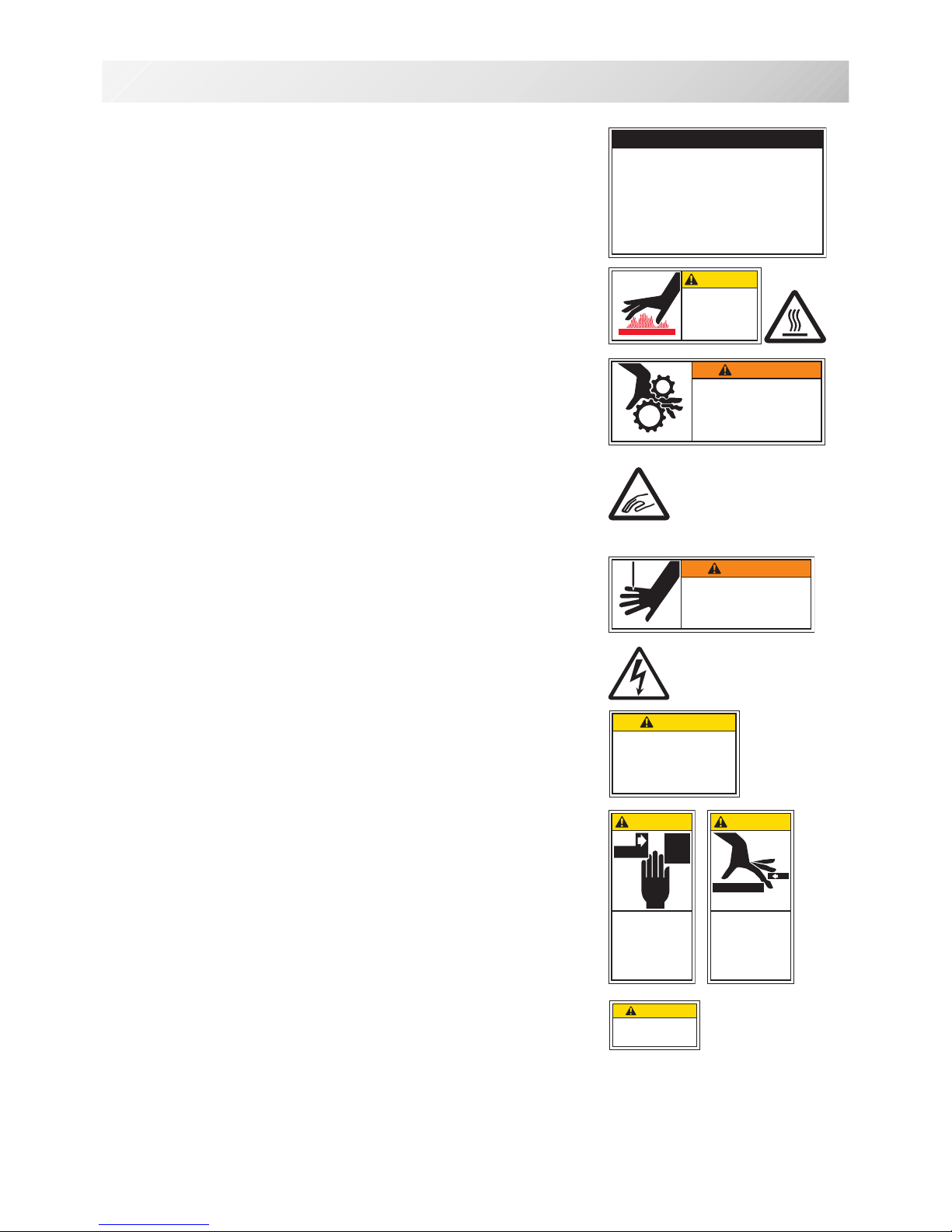
Safety Instruction Sticker for servicing, operating and
maintaining
Caution Sticker for hot surface
( on all pulse motors, the motors may reach a certain temperature after
long time running, which can reach up to 60°(C )
Trapping hazard
( please see sketch for location )
Trapping hazard wherever this label is found
Injury risk warning for all needles
Shock hazard on all electrical components
Injury risk on moving head(s)
Injury risk on frame and carriage
Laser beam (Class 1)
Do not stare into the beam.
ES-HMF-5113-0
WARNING
Shut the cover when starting the
machine. Do not put hands in
while the machine is running.
Fear of serious injury.
ES-HMF-5127-0
SAFETY INSTRUCTIONS
1. Machine must be operated by well trained
person only.
2. Machine must be used for original purpose
only, do not use for other purpose.
3. Shut machine off to oil, adjust or service.
4. Do not operate machine fill close and fix
cover.
5. Do not leave running when unattende.
ES-HMF-5128-0
Do not touch
hot surfaces.
CAUTION
ES-HMF-5112-1
Fear of serious injury.
Keep fingers away from
the needles while
the machine is running.
WARNING
ES-HMF-5117-0
CAUTION
Keep hands away from the
moving heads while the
machine is running.
Possibility of injury.
ES-HMF-5114-0
CAUTION
Possibility
of injury.
Keep hands away
from the drive
frame while
the machine
is running.
ES-HMF-5115-0
CAUTION
Possibility
of injury.
Do not put fingers
in holes or grooves
of the table.
Laser beam (Class 1)
CAUTION
Do not stare into the beam.

-D2 -8
SETTING UP THE MACHINE
2_1 N401
2-1
Assemble machine unit
1. Insert thread stand felt on the thread stand.
2. Turn the thread guide pillar clockwise with a
3 mm hexagonal driver until tight.
3. Install the thread guide bracket with
supplied screws (pan head screw M4 X 8 2
pcs).
4. Loosen the screw with a offset driver and
remove the red shipping collars that are
equipped on the both side of the guide bar.
(
Keep the shipping collars. It is necessary
when packing.)
5. Raise slowly the control box to the front
then fix it with 2 screws (upper and lower).
6. Install the tubular frame arm for embroidery.
Please refer to (page 6-1) "Installing and
removing the tubular frame arm".
Or, Install the cap frame for the cap
embroidery. Please refer to (page 7-1)
"Installing and removing the cap drive
frame".
7. Insert built-in stylus into the holder (slot) of
control box.
When taking the machine apart in case of
packing, the process is opposite of
assembling the machine. Please do exactly
the opposite way of assembling.
When packing the machine up for
transportation, be sure to select the eighth
needle and fix it with shipping collars on the
both side of the guide bar.
1
2
3
Thread stand
felt
Thread guide pillar
Thread guide
5
Screw
4
Screw
Screws
Stylus
7
-D2M4 -92-2 LC01
2-2
SETTING UP THE MACHINE
for qualified personnel only
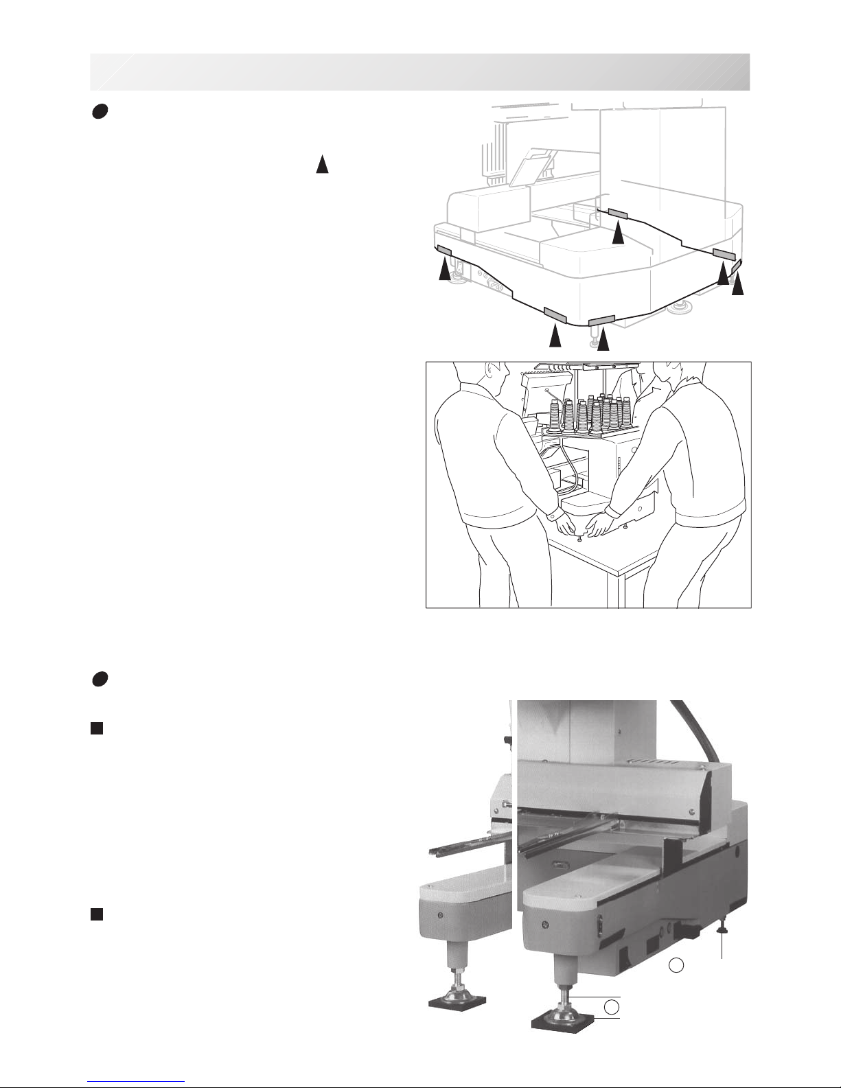
How to carry machine
The unpacked machine should be carried by 3
person with the hand position at
mark
shown in photos.
2
Ocasional
adjusters
Adjusters
Rubber mount
1
Right side
Left side
Rear side
Machine installation
Do not run the machine before setting it
properly.
Make sure of taking the following steps to
set the machine.
1. Pick up rubber mount (3 places) on the
stand then mount machine on the stand.
Then adjust machine level by adjuster on
foot and lock the each nut.
Be sure to use rubber mounts. Also be sure
to use robust stand that enables to adjust
level of the machine and endure machine
weight and vibration.
2. Please two occasional adjuster light touch
to stand and lock.

-D22-3 M201
2-3
SETTING UP THE MACHINE
for qualified personnel only
3. Remove needle plates and bobbin cases
from all the heads.
4. Lower the needle holder by pressing down
with fingers on Fig. 4.
5. Turn main shaft by using the hexagonal
driver in direction shown with arrow mark on
Fig. 5 and set the angle of the adjustment
disk as shown in fig. 6.
6. Check the needle depth on all needles.
Pull white plastic ø17 measuring gauge in
and out of rotary hook in fig. 7. If height
gauge brushes lightly against tip of needle,
needle height is correct. If not, loosen
needle bar block screw to adjust, then retighten after adjustment.
(Remove the gauge when finished).
Note: Height gauge is contained in tool box.
7. Turn main shaft slightly in direction shown
by the arrow mark.
Then set the angle of adjustment disc as
shown in Fig. 8.
Note the space or timing between needle
and tip of rotary hook as shown Fig. 9, 10.
If the space is too open or too close, loosen
3 screws of shuttle to adjust. Make sure to
tighten 3 screws after adjusted the space.
(The timing is set exactly at the factory.
However, in some cases timing is inadvertently thrown off from handling during shipment.)
8. Turn main shaft in direction and set to C
point.
Place the bobbin and bobbin case in the
hook and replace the needle plate and
tighten.
9. Machine is now ready for sewing.
Needle holder
Tip of rotary hook
Needle
L+5°
Cord
Rotary hook
Needle
ø17 Measuring gauge
L+23°
Screws
Needle
Tip of rotary hook
0.1~0.15mm
Head bed
C
Fig. 10
Fig. 9
Fig. 8
Fig. 7
Fig. 6
Fig. 5
Fig. 4
-D2 -102-4 M101
2-4
SETTING UP THE MACHINE
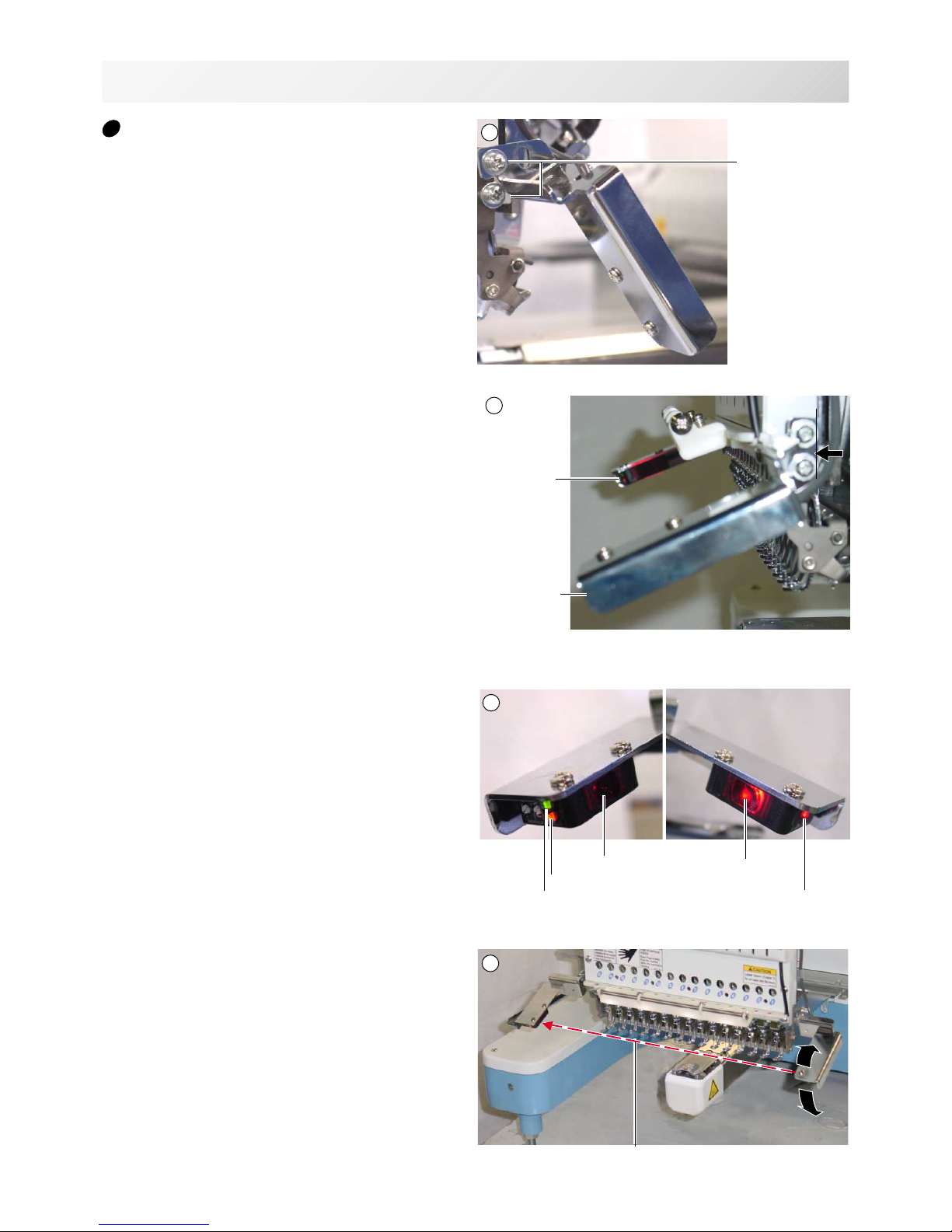
Assemble safety sensor (Option)
Safety sensors are set at a provisional position
for transportation. Please reset the safety sensors at normal positions for adjustment.
1. Unscrew set screws at lower points on the
safety sensors on right and left sides.
Loosen set screws slightly at upper points
on the safety sensors.
2. Set the right and left safety sensors at the
positions as shown in a photo by turning
them to the front side.
At this time, make sure the part on the
sensors indicated by an arrow shall be set
vertically, and set safety sensors both right
and left at parallel positions each other with
viewing them from the side.
The set screw on the right safety sensor
shall be tightened to the level that the
positions of the safety sensors can be
adjusted vertically.
3. Turn on the machine and confirm a lamp for
receiving ray (orange) is on when the way of
sensor ray is not blocked.
4. Confirm if the lamp for receiving ray
(orange) is turned off by blocking the way of
sensor ray by a hand or other.
Tighten the set screw firmly.
1
2
3
Set screw
Sensor left
Sensor right
Sensor right
Sensor left
Ray receiver
Ray projector
Power indicator
Lamp for receiving ray
Power indicator
Way of sensor ray
4

-D22-4b M201-9
2-4b
SETTING UP THE MACHINE
Assemble Wide X-carriage
(Option)
Wide X-carriage is packed separately from
machine.
When you set machine up, please install Wide
X-carriage on machine.
1. Move Stay at middle of Y-carriage.
2. Put Wide X-Carriage on Stay and adjust
screw hole position.
3. Fix Carriage by Flat head screw (M4x8) at
hole position [1] and [2](for the purpose of
positioning).
4. [3][4] Fix Carriage by Fixing screw (Cap
M4x8, Spring washer, Plain washer) at hole
position [3] and [4].
5. Unscrew Flat head screw from [1] and [2]
and fix by Fixing screw (Cap M4x8, Spring
washer, Plain washer).
6. Loosen screws on BOX terminal and take
cover out.
7. Insert X-Motor cable into BOX terminal and
connect with X-Motor relay cable.
Fix terminal for earth connection for X-Motor
cable and X-Motor relay cable together.
8. Fix X-Motor cable by Cable clamp.
9. Close cover of BOX terminal.
Please be sure cables do not get caught by
cover.
Please reverse procedure when remove the
X-Carriage.
Wide X-carriage
X-Motor cable
1
2
Cable clamp
Terminal for earth connection
Stay (left)
Stay (right)
Stay (left)
Stay (right)
1
4
3
2
1
4
3
2
X-Motor relay cable
BOX terminal
Cover of
BOX
terminal
8
9
3 4
5
6
7
Front
-D2 -122-5 M419
2-5
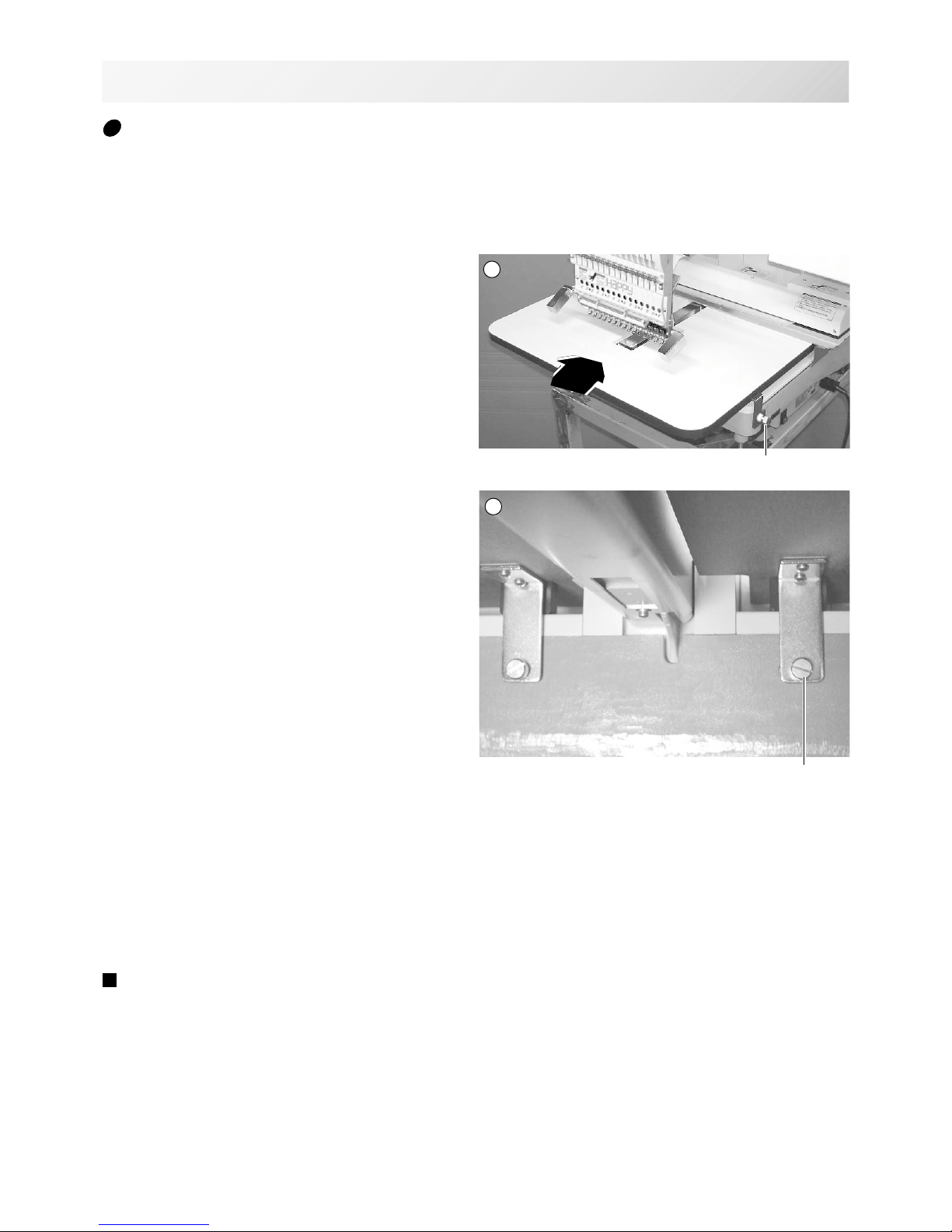
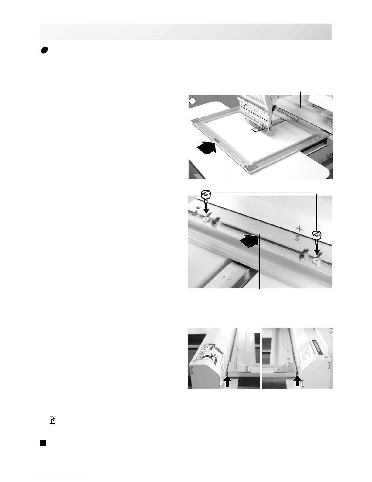
SETTING UP THE MACHINE
1. Insert Knob screw to right and left side of
machine.
And set table like right side picture.
Please insert table bracket trench to the
knob screw.
2. Tight 2 knob screw on under the table for fix
table.
3. Tight 2 knob screw on side of the table.
Please reverse procedure when remove the
table.
Knob screw
Knob screw
1
Assemble table (Option)
Installing theTable or the Table (border).
2
-D2 -13
2-5b M419
2-5b
SETTING UP THE MACHINE
1. Fix the border frame under the bracket of
the X carriage and tighten the knob screw
completely.
Clearance between X-carriage and Border
Frame at right edge and left edge should be
equal.
2. Select Frame Type “Border”.
Please refer in this manual page “FRAME
CONFIRMATION” for “Frame selection”.
20-2
Please reverse procedure when remove the
border frame.
1
X carriage
Border frame
Assemble border frame (Option)
Bracket
Knob screw
-CD -152-5c J520
2-5c
SETTING UP THE MACHINE
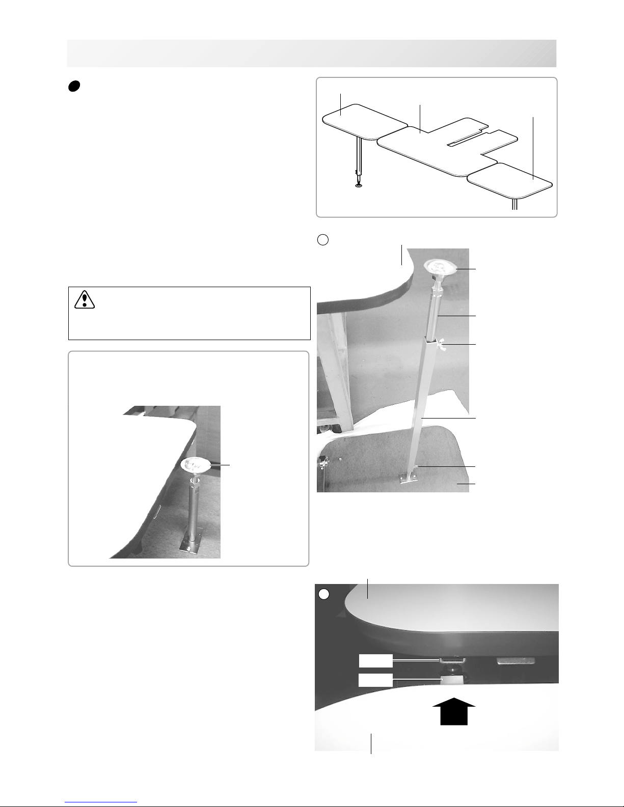
Assemble Expand side table (Option)
1. Set Stay on Expand Side table.
Put Expand Side Table under Border table
and set Stay by Wing Bolt.
Adjust height of Adjuster by Wing bolt to the
same height as surface of border table.
Stay A
Border table
1
2
Wing bolt
Stay B
Adjuster
Wing bolt
Expand side table
In case you need to set Expand Side Table
on same level of machine stand (or table), set
Adjuster to Stay A directly.
Adjuster
2. Turn Expand Side Table and join tables with
inserting Prop B into Prop A.
Border table
Expand side table (Left)
Expand side table
(Right)
CAUTION: To prevent accidents.
Table may be slanted.
Tighten Wing bolt to fix height of stay.
Border table
Expand side table
Prop A
Prop B
-CD -16
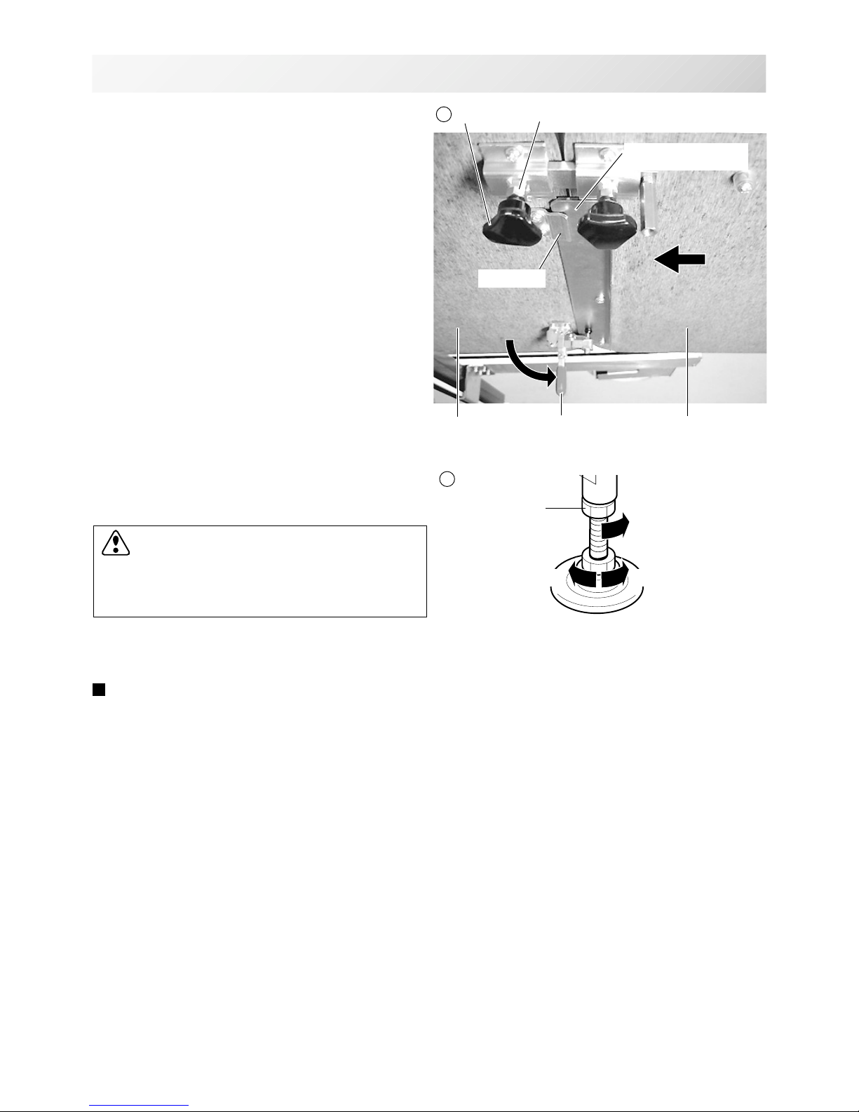
3. Confirm that Middle support plate enters to
the space between table and Prop plate and
there is no opening between tables.
Tighten Knob bolt of Prop A at Border table
and fix Lock nut.
Then set Clamp.
4. Adjust height of Expand Side Table by
Adjuster and fix by Lock nut.
Please reverse procedure when remove the
Expand Side Table.
2-5d J520
2-5d
SETTING UP THE MACHINE
Lock nutKnob bolt
Clamp
Prop plate
Middle table support
plate
Border table
Expand side
table (R)
3
Lock nut
Fix by Lock nut
Higher Lower
4
CAUTION: To prevent accidents.
Table may be slanted.
Please do not load any objects on Expand
side table.
-CD -122-6 FB01
2-6
SETTING UP THE MACHINE
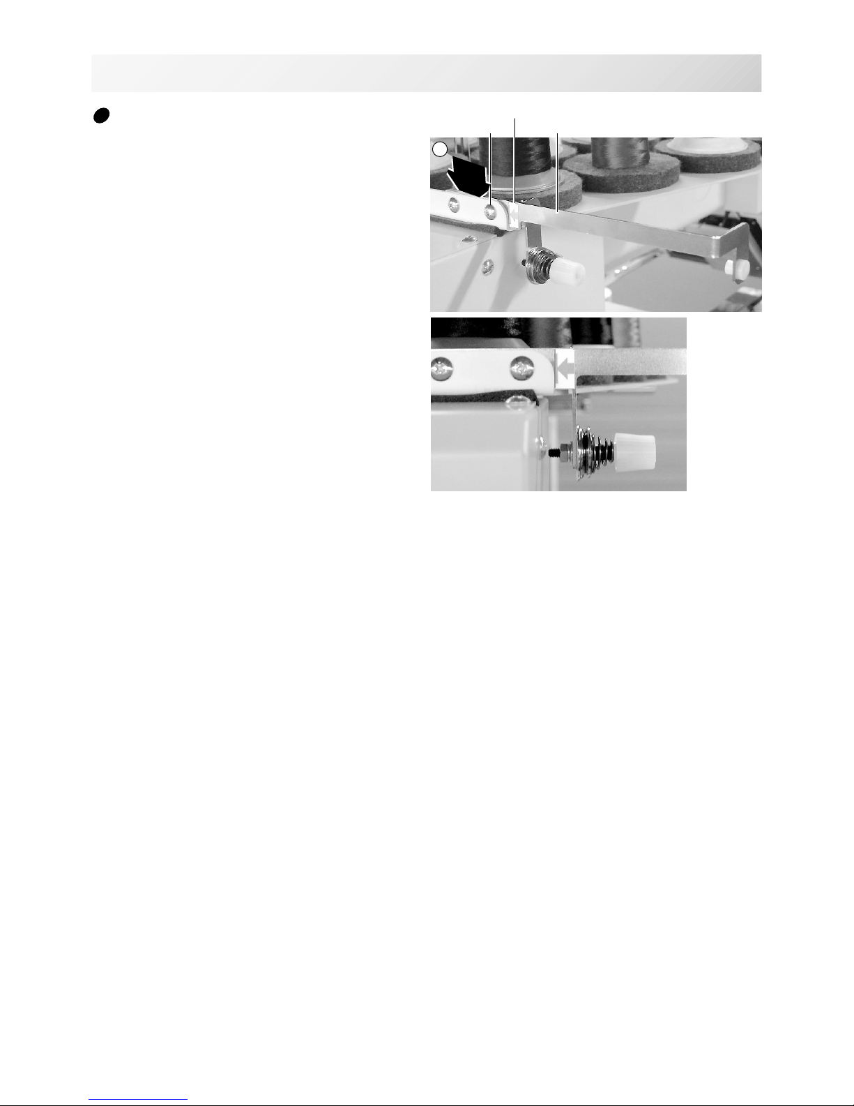
Assemble bobbin thread guide
(Option)
1. Install the bobbin thread guide with supplied
screws (pan head screw M4 X 6 2 pcs).
( Showing following pictures, Please square
left end of sticker with right end of thread
stand)
Bobbin thread guideScrews
Sticker
1
-CS -11
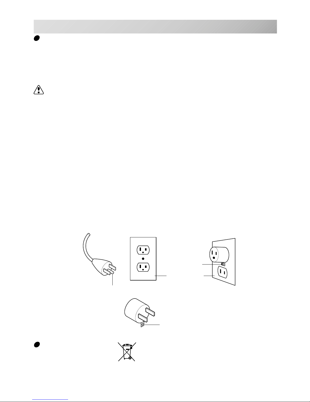
Grounding instruction (for type of 120V)
This product must be grounded. In the event of malfunction or breakdown, grounding provides a
path of least resistance for electric current to reduce the risk of electric shock. This product is
equipped with a cord having an equipment-grounding conductor and a grounding plug. The plug
must be plugged into an appropriate outlet that is properly installed and grounded in accordance
with all local codes and ordinances.
DANGER – Improper connection of the equipment-grounding conductor can result in a
risk of electric shock. The conductor with insulation having an outer surface that is green with or
without yellow stripes is the equipment-grounding conductor. If repair or replacement of the cord
or plug is necessary, do not connect the equipment-grounding conductor to a live terminal.
Check with a qualified electrician or serviceman if the grounding instructions are not completely
understood, or if in doubt as to whether the product is properly grounded.
Do not modify the plug provided with the product – if it will not fit the outlet, have a proper outlet
installed by a qualified electrician.
This product is for use on a nominal 120 V circuit, and has a grounding plug that looks like the
plug illustrated in sketch A in Figure. A temporary adaptor, which looks like the adaptor illustrated in sketches B and C, may be used to connect this plug to a 2-pole receptacle as shown in
sketch B if a properly grounded outlet is not available. The temporary adaptor should be used
only until a properly grounded outlet can be installed by a qualified electrician. The green colored rigid ear, lug, and the like, extending from the adaptor must be connected to a permanent
ground such as a properly grounded outlet box cover. Whenever the adaptor is used, it must be
held in place by the metal screw.
2_6 I916
2-7
SETTING UP THE MACHINE
Disposal of a battery
A battery is had built-in to this embroidery machine.
When you dispose of a battery, according to each country or a method determined in each area,
please dispose appropriately.
Metal screw
Cover of grounded
outlet box
Grounding pin
Grounding means
Grounding methods
Adapter
A
B
C
-D2 -14
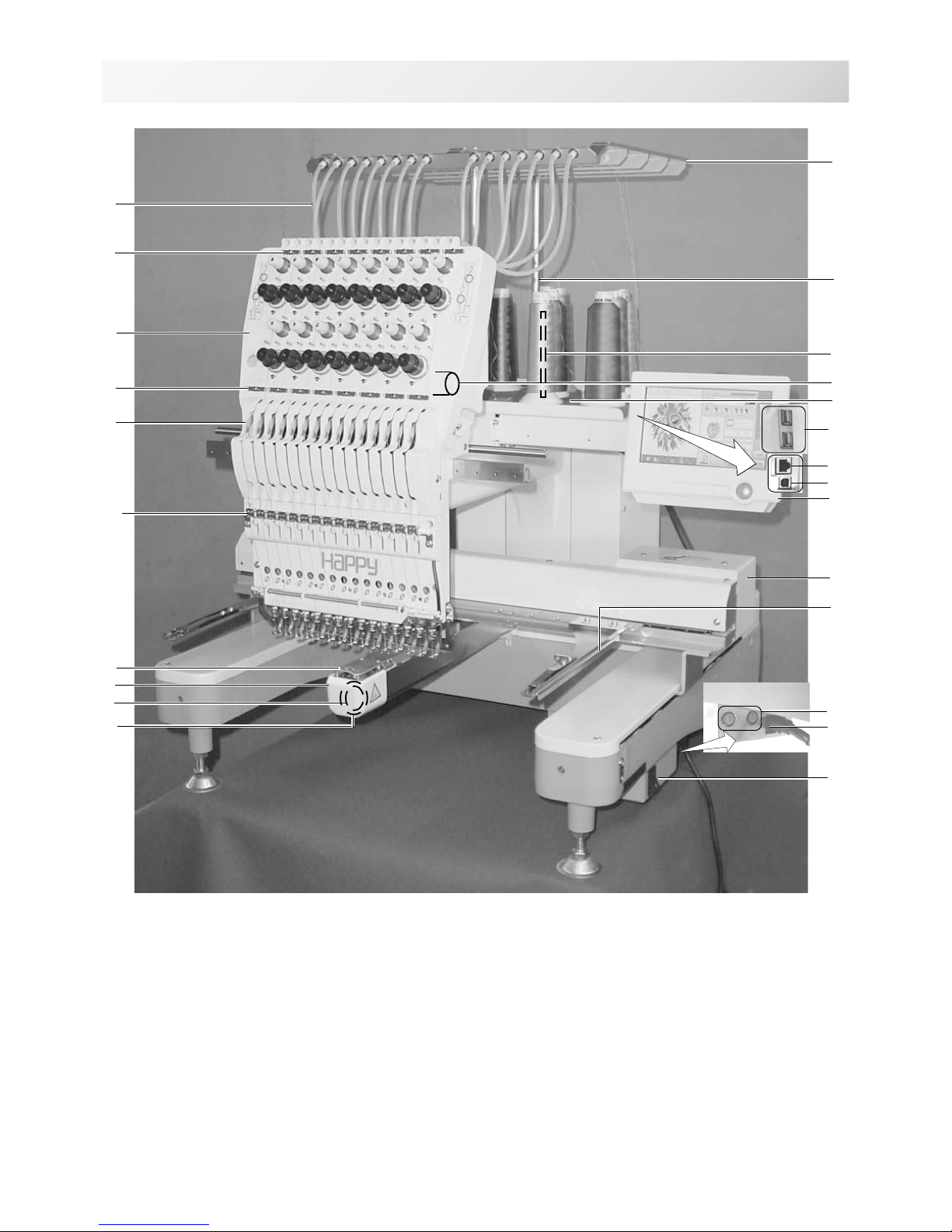
MAIN PARTS
1. Hook cover
2. Hook
3. Bobbin case
4. Needle plate
5. Take-up lever
6. Lower rectifier
7. Thread tension
8. Upper rectifier
9. Guide tube
10. Thread guide support
11. Thread guide
12. Thread check spring
13. Thread stand pin
14. Thread stand felt
15. Needle bar selection knob
16. Control box
17. LAN port
18. USB port
(Standard-A receptacle)
19. Frame hold arm
20. Carriage
21. Fuse (6A)
22. Terminal box
23. Power switch
24. USB port
(Standard-B receptacle)
1
2
3
4
5
7
8
9
10
11
12
13
14
15
16
19
3_1 M620
3-1
20
21
22
23
18
6
17
24
-D2 -153_2 M717
3-2
MAIN PARTS
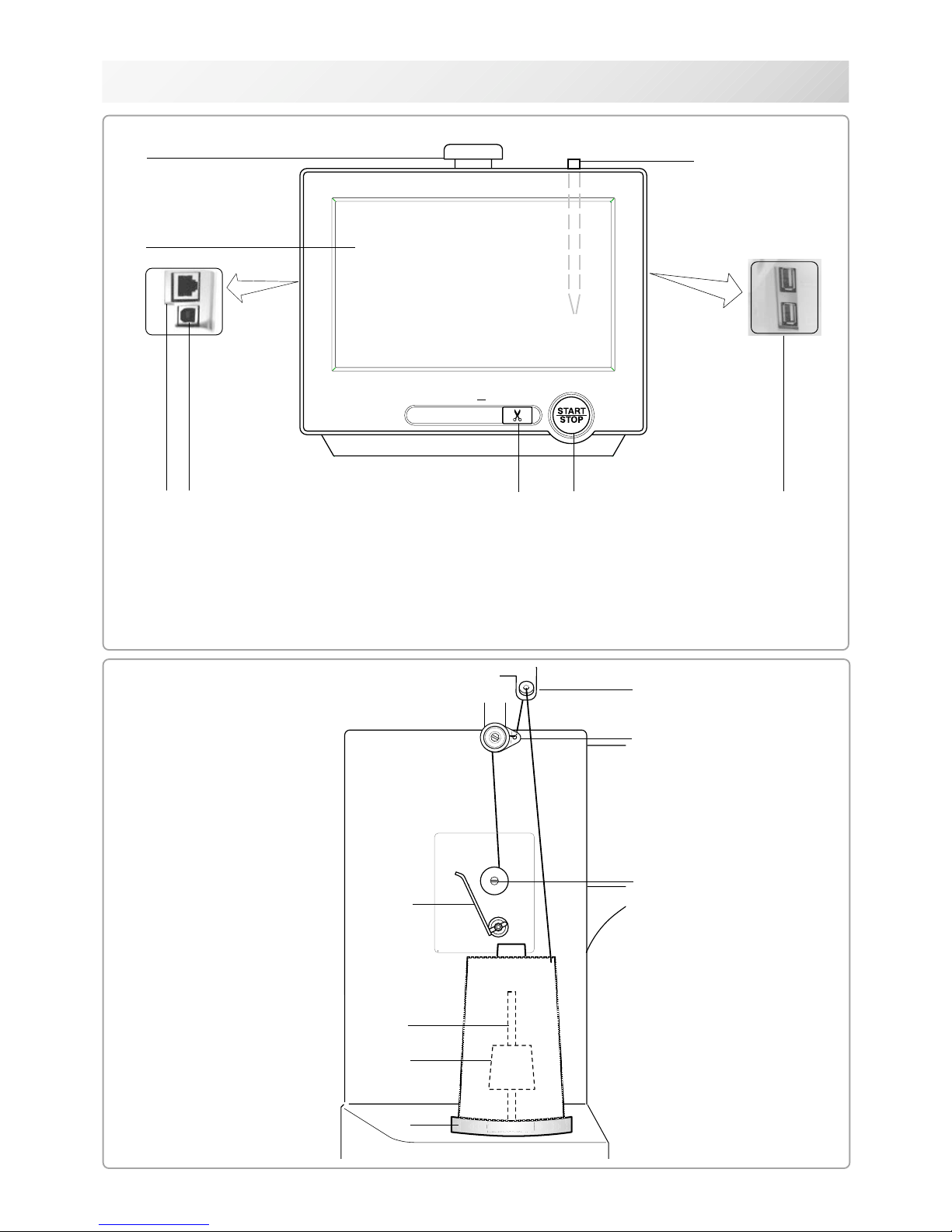
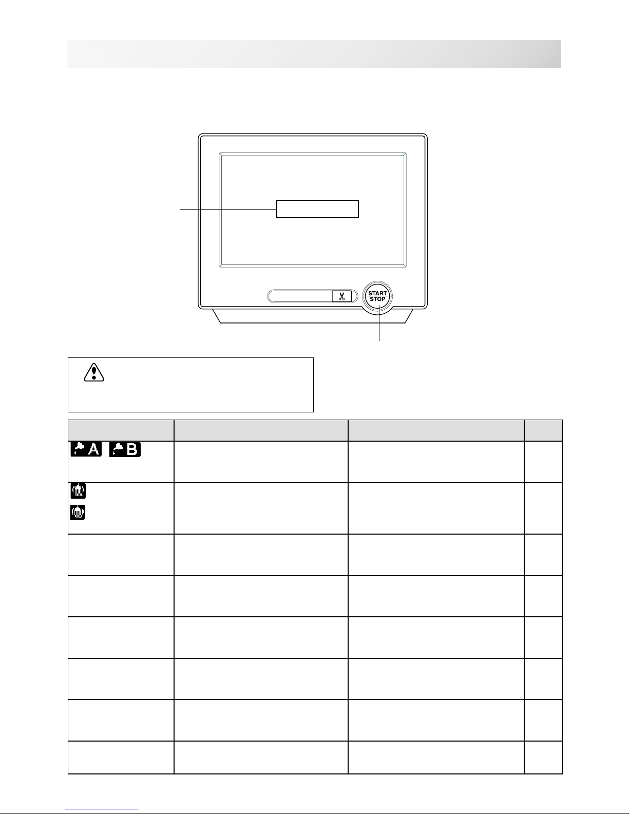
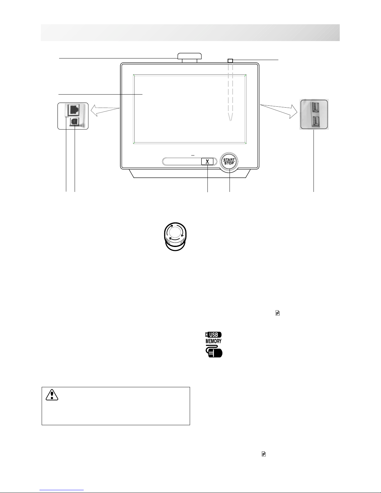
CONTROL BOX
4
5
1. Emergency stop button
2. Display (L.C.D.)
3. LAN port
4. Thread cut button
5. Start/Stop button
6
5
7
6
1
4
2
3
1. Thread guide
2. Thread tension
3. Spindle
4. Lever
5. Thread stand pin
6. Plastic spring
7. Thread stand felt
BOBBIN WINDING (Option)
3
7
1
2
16
8
6. USB port (Standard-A receptacle)
7. USB port (Standard-B receptacle)
8. Stylus
-S2 -12
HOW TO READ THESE INSTRUCTIONS
3-3
3_3 MB15
The instructions in this manual have been formatted as follows:
Written instructions will be provided on the left side of the page while graphics depicting the
necessary steps are provided on the right.
Graphics on the far right will show the display after performing the steps indicated.
This indicates an additional
explanation on an operation
elsewhere in the manual for
more detail.
AWords marked with a "*" are explained in
"EMBROIDERY TERMS" at the end of this
instruction manual.
CAUTION: To prevent accidents.
This will appear for items related to your safety.
CAUTION: To avoid problems.
This will appear for items related to potential problems.
Order of operation
Indicates supplementary
explanation regarding a
given operation or action.
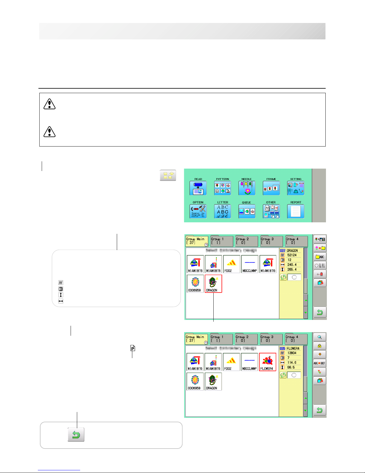
1. When the machine is stopped, press .
2. Select "PATTERN".
The display indicates the current pattern.
The left side of display shows the number, name
and details for the current pattern.
Number of stitches
Number of Color change number
Height
Width
3. Select *pattern data.
This pattern will be selected.
3-3
Selected pattern data
Press to return to Menu mode.
Operation key
-D2 -16
MESSAGES
3-4
3_4 2NC17
Below is a list of possible messages that may appear while operating the machine, along with
an brief explanation and suggested actions to take as a result.
Press the screen (any location is okay), then message will disappear.
EGASSEM NOITANALPXE NOITAREPO EGAP
liootecalP
yalpsidehtnoretteldetangiseD
.detacirbuleboteudsi
detacidninoitacolehtetacirbuL
.BroAyb
niegapdetacidniehtotrefeR
.launamsiht
1-32
fogninaelC
koofyrator
fogninaelC
tucdaerht
efink
ehtdnakoohyratorehtnaelC
.efinkgnittucdaerht
ehtninoitcurtsnihtiwnaelC
.egapecnerefer
2-32
hctiwSpotS>>
deppotssienihcamehT
sawnottubpotsehtesuaceb
ehtgnirediorbmeelihwdesserp
.ngised
otnottubpots/tratsehtsserP
.gniwesemuser
dnE>>
deppotssienihcamehT
ehtdehsinifsahtiesuaceb
.ngised
,niagangisedwesothsiwuoyfI
nometidepoohylwenesaelp
pots/tratssserp&enihcam
.nottub
potSegnahC>>
uoyesuaceb,deppotsenihcaM
egnahcroloctapotS"desu
.noitcnuf"tniop
pots/tratsehtsserpuoynehW
tceleslliwenihcameht,nottub
emuserdnaroloctxeneht
.yllacitamotuagnirediorbme
?roloC>>
ehtesuacebdeppotsenihcaM
neebtonsahroloctxen
.detceles
eldeentxentcelesesaelP
noitceleseldeenybrebmun
tratsehtsserpnehtnottubpots/
.nottub
kaerBdaerhT>>
esuaceb,deppotsenihcaM
.nekorbdaerhtnibbobroreppu
rodaerhtreppudaerhtesaelP
sserpnehtdaerhtnibbobkcehc
emuserotnottubpots/trats
.gniwes
dneecarT>>
deppotssienihcamehT
ehthtiwdehsinifsahtiesuaceb
.ecartngised
.KOfinottubpots/tratsehtsserP4-6
C-7
Start/Stop button
Message
>>Stop Switch
CAUTION: To prevent accidents.
The embroidery frame may move. Please
keep hands clear for your safety.
-D2 -17
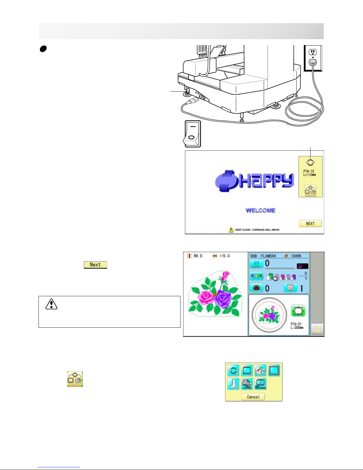
TURNING THE MACHINE ON
2. Connect the power plug to an electrical
outlet.
3. Turn on the power switch.
Indicates the select frame.
Please confirm the emergency stop button has
been released.
Push the power switch firmly so it will remain on.
4. In case you do not need to change frame
type, Press
.
After the carriage and frame move slightly, the
embroidery frame will return to the previous
position automatically.
Machine becomes ready for operation.
3_5 M620
3-5
How to turn on the machine
CAUTION: To prevent accidents.
The embroidery frame and carriage will move.
Please keep hands clear for your safety.
Power switch
1. Connect the power cord to the inlet on the
right side of the machine.
In case you want to change frame type,
Press
.
ON
OFF
Selected frame
-D2 -18
TURNING THE MACHINE ON
3_6 N101
3-6
DANGER: To reduce the risk of electric shock.
Never leave the machine unattended when plugged in.
Always unplug this machine from the electrical outlet immediately after use and before performing any maintenance on it.
WARNING: To reduce the risk of burns, fire, electric shock, or injury to persons.
Do not unplug by pulling on cord. To unplug, grasp the plug, not the cord.
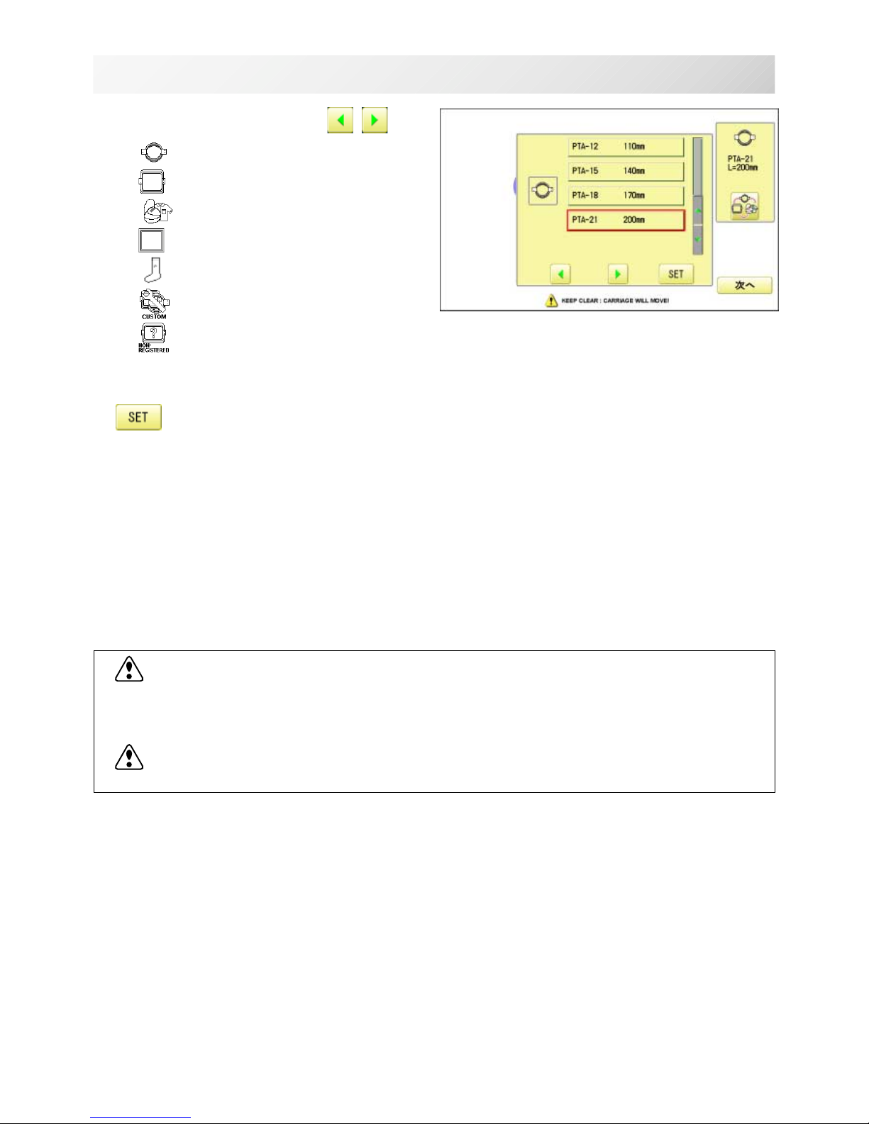
5. Select the desired frame with
.
: Tubular round frame
: Tubular square frame
: Cap and One-point frame.
: Border frame (for HCD2)
: Sock frame
: User-defined frame
: Non registered
6. Select desired type of frame and Press
.
The display returns to the view of Step 3.
To disconnect, switch the power switch to the
off position, then remove plug from outlet.
-D2 -19
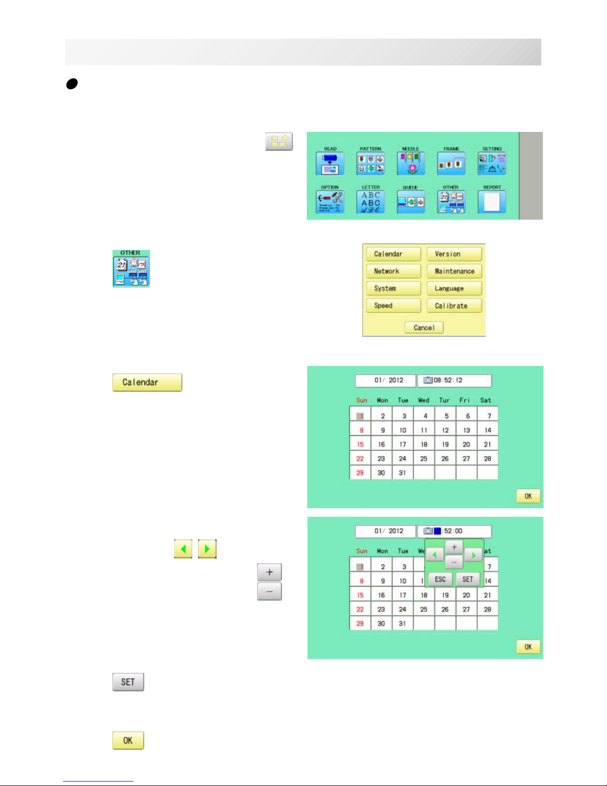
1. When the machine is stopped, press .
2. Press
.
3. Press .
Current year, month date and time is displayed.
4. Select year/month, time or date.
Press right /left of to select the
setting point, and press up/down of
to
select the number of year, month and time.
5. Press
.
The date is fixed.
6. Press to return to Menu mode.
Calendar and clock setting
Setting the calendar and clock lets the machine advise when oiling and other maintenance is
scheduled to occur.
TURNING THE MACHINE ON
3-7
3_6 M620
-D2 -21
THE CONTROL BOX
3_8 M717
3-8
2. Display
Shows the embroidery design name, the number of
the current needle and other machine generated
messages.
Menu and keys in the display can be operated with
a finger or built-in stylus.
3. LAN port
You can connect PC with a LAN.
4. Thread trim button
The Machine will cut the upper and lower thread
when this button is pressed.
In case you press and keep (around 2 sec.), you
can cut only bobbin thread.
5. Start/Stop button
This button starts the machine.
When pressed, while the machine is running, the
machine will stop.
Green .......... Machine ready to sew.
Main menu also accessible by
pressing MENU, which causes menu
to display.
Blinking red .Indicates the upper thread has
broken or the Bobbin thread has run
out.
Red .............Machine is running.
Orange ........ Machine has detected an error.
An error number will be shown on
the Display. 24-1
6. USB port (Standard-A receptacle)
USB memory socket.
USB mouse socket.
Menu and keys in the display can be operated with
a commercial USB mouse.
Press right mouse button to show a mouse pointer
in the display.
7. USB port (Standard-B receptacle)
Use this port to connect the machine with PC via
USB.
8. Stylus
Stylus can be used for pressing menu and keys in
place of fingers.
Most operation can be done by fingers. Stylus is
required for some operation such as calibration for
the touch panel LCD. 22-3c
Insert a stylus into the holder (slot) of control box
when not used to prevent loss of the stylus.
CAUTION: To prevent accidents.
If you Press thread trim button, the needle will
penetrate the fabric. Please keep your hands
clear for your safety.
1
2
4
5
6
16
1. Emergency stop button
When pressed , the power is switched off
and the machine stops immediately.
The emergency button locks when
pressed.
To unlock, turn the emergency button to
the right
(Arrow direction) then release. The button will
unlock.
Use this button only for emergency.
73
8

-D2 -21
3_A MB14
3-9
DRIVE MODE
Drive key
The each key menu will be shown.
Frame forward
This creates direct designations to the position and
data to the designated sewing position.
Piece 16-2
If "Repeat" is set, this allows the frame to move to
the beginning of any piece at will.
Change (Color position ) 9-7
This moves the frame to the beginning of any Color
change number at will beginning of color.
Stitch (Number of stitches ) 9-6
This moves the frame to any stitch at will.
Forward and Back-ward
Needle bar
selection
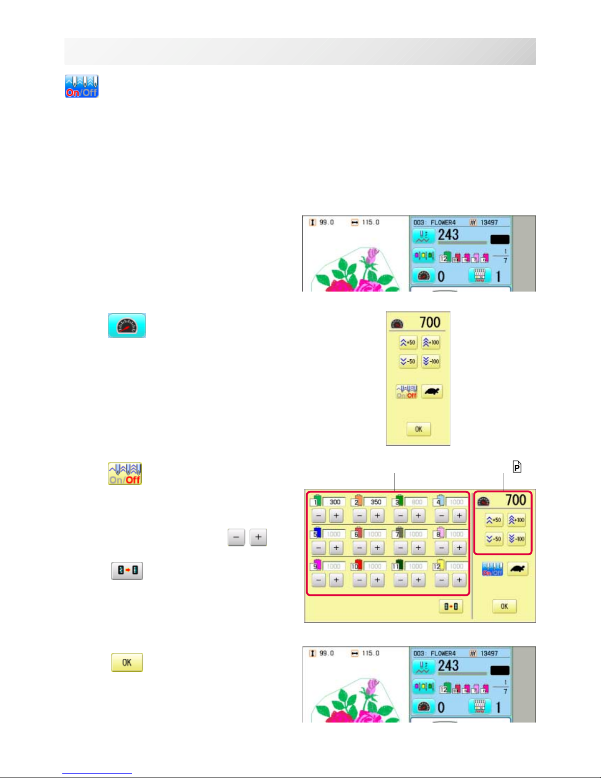
Speed control
Needle change
Drive speed
Control embroidery speed.
The speed can be controlled while embroidering.
Speed control
Press the + button to increase the machine sewing
speed and the - button to lower the machine speed.
is displayed on the LCD display.
i-Custom
(default display)
Frame move
Needle bar selection 5-E
For each color change in a given pattern, the needle number loaded with the correct color thread is
assigned by the operator.
Low speed operation (OFF state)
Press the button to turn "ON" state.
Low speed operation (ON state)
Press the button to turn "OFF" state.
Speed setting by needle (OFF state)
Press the button to turn "ON" state.
Speed setting by needle (ON state)
Press the button to turn "OFF" state. 3-9c
Color position forward
Move the frame to the beginning embroidery
position of the previous or later color position
number
Stitch number forward
Move the frame forward or backward by the
stitch number displayed in each button.

-D2 -22
Frame move
Selection the way of frame movement and
Move frame.
Frame change
Change the frame to be used.
Design centering
Move design to the center of frame.
Center
Moves the embroidery frame to the center automatically.
Frame out
Move frame to the front position which was set
before.
Press (Position) to return the frame to the
original position before frame out position.
It is convenience if hand work is required in the
middle of embroider process.
Position
When sewing is interrupted in the middle of a
design, this returns the frame to current sewing
position regardless of where frame may have
been moved with the arrow keys after interrupt.
target design.
3_A MB14
3-9b
DRIVE MODE
Needle change
Change the needle bar directly to the indicated
needle number on the button.
Change
Move the sewing head to the adjacent needle in
the direction of the arrows.
Jump (Off)
The machine can embroider.
Jump (On)
Machine becomes jump and the machine
doesn't embroider.
i-Custom 21-1
You can place frequently used display and key icons freely on the right side of Drive mode screen.
Original point return
This returns the frame to *pattern origin point.
After performing this action once, repeating this
again will cause the frame to return to the
previous
position.
Origin registration
Register the current frame position as origin.
Trace
When pressed while at the beginning of design,
the embroidery frame moves following the outer
edge of the design. This allows you to compare
the design size and position against the frame
before sewing.
Indicate target design on LCD panel when nonshowing design.
If you press this key and hold, re-display your
Locate
Locate will restore the position of the frame to
the last point before a power failure even if the
point of origin or the pattern itself were
changed.

-D2 -24
3_A MB14
3-9c
DRIVE MODE
Frame move key
The frame moves toward direction of the arrow
mark.
Fast move
Press this key one time to move the frame
faster toward the direction of the arrow.
Press this key one more time to cancel this
function.
Pointer (Option)
Turn on and off the laser pointer.
Quick move
First press this key and then the arrow key to
move the frame toward the edge of the embroidery
area in the direction of the arrow.
Quick embroidery design data position move
First press this key and then the arrow key to
move the frame where the design data can be
embroidered at
the edge in the direction of the arrow.
-S2 -16
3_A MA05
3-9d
DRIVE MODE
Speed setting by needle (ON state)
Embroidery speed can be set by needle.
If speed by needle exceeds the speed set at Drive speed setting, the value of speed turns gray
and speed by the needle is applied to the speed set at Drive speed setting.
You can be set up taking the following steps.
1. Press .
2. Press
.
3. Change the setting on the needle number
you would like to change with
.
Press when returning the setting on all the
needle numbers to maximum.
4. Press .
The screen returns to Drive mode.
Speed setting by needle Drive speed setting 3-9
-D2 -24
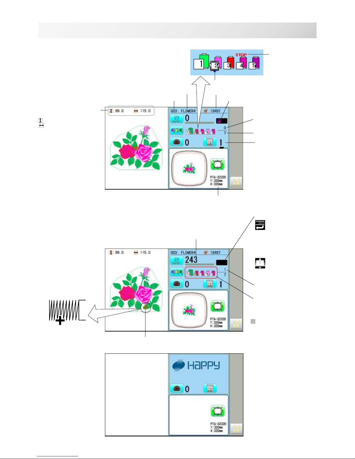
Memory # of selected pattern
Currently-selected
needle
Number of stitches sewn up to now
Name of selected pattern
Top
When beginning an embroidery
Machine stopped during embroidering
Display example
Status
Top
This indicates that the
machine is ready to start
sewing from the "top"
memory position of the
pattern.
Frame out
This indicates that a
frame out is occuring.
3_A M620
3-A
DRIVE MODE
Pointer
Color change number
sewn up to now
Stitches of pattern
Needle number and color
*Color change number
Pointer indicates the
position of actual stitch
point.
If a needle number is not
assigned to a Color
change number, the
default color will be
assigned automatically.
Shift to left when color
change.
Size of pattern and distance
Heigh
t Width
Current *Color change
number
Mark for color
change stop
Mark for frame out
Selected frame
Display if the machine has no design
in memory
 Loading...