

Happy Industrial Corporation C Instruction Manual

HCS
Computerized Compact Single Head Embroidery Machine
INSTRUCTION BOOK
c
Original instructions
BDL901-8


INDEX
0-1
IMPORTANT SAFETY INSTRUCTIONS.. 1-1
WARNING LABELS & THEIR LOCATIONS .....
SETTING UP THE MACHINE
Remove the machine from box............... 2-1
Accessories ............................................ 2-2
Assemble machine unit .......................... 2-3
Machine installation ................................ 2-4
Grounding instruction ............................. 2-6
Disposal of a battery............................... 2-6
MAIN PARTS ............................................ 3-1
HOW TO READ
MESSAGE ................................................ 3-4
TURNING THE MACHINE ON
How to turn on the machine.................... 3-5
Display contrast ...................................... 3-6
THESE
INSTRUCTIONS .............
1-2
3-3
Reading embroidery pattern data from
the PC ..........................................................
Reading embroidery pattern data from
Memory media reading........................... 5-6
Read pattern data in PC ........................5-7b
How to select patterns from memory...... 5-A
Erasing patterns from memory ............... 5-B
Erasing all designs ................................. 5-D
NEEDLE BAR SELECTION ...................... 5-E
SEWING WITH TUBULAR FRAMES
Installing and removing the frame base.. 6-1
How to hoop ........................................... 6-2
Putting the hoop on the machine............ 6-3
Starting to embroider .............................. 6-4
CAP FRAME (OPTION)
5-4b
Calendar and clock setting ..................... 3-7
THE CONTROL BOX................................ 3-8
DRIVE MODE ........................................... 3-A
DRIVE MENU............................................ 3-B
MENU........................................................3-C
GUIDE....................................................... 3-D
INSERTING A NEEDLE............................ 4-1
SELECT NEEDLES AND THREADS....... 4-2
BACKING MATERIALS............................. 4-3
BOBBIN WINDING
Winding the bobbin................................. 4-4
Removing the bobbin.............................. 4-5
Inserting the bobbin ................................ 4-5
Adjusting bobbin thread tension ............. 4-5
Inserting the bobbin case ....................... 4-5
Changing the needle plate...................... 7-1
Installing and removing the cap drive frame...
Normal cap frame ................................... 7-5
Wide cap frame ...................................... 7-8
Starting to embroider .............................. 7-B
ADJUSTING THE THREAD TENSIONS .. 8-1
ADJUSTING THE LASER POINTER (OPTION)...
SEWING
What to do if the thread breaks while sewing.
Stopping and resuming sewing .............. 9-1
Loss of power while embroidering .......... 9-2
Moving the hoop while embroidering and then returning to
the correct location (Position) .......................................
Moving back to the starting point (Origin)9-3
Going back to the beginning of the design (Top) ....
7-2
8-2
9-1
9-3
9-4
THREADING THE MACHINE
How to thread upper thread.................... 4-6
BASIC MODE............................................ 4-8
MACHINE SETTINGS............................... 5-1
PREPARATION OF PATTERN DATA
Connecting to a PC by Serial or USB connection...
5-4
Placing the design in the center of the selected
embroidery frame
Rotating and mirroring designs (Convert) ..
Starting in the middle of a design (Position)...
DISPLAYING THE PATTERN IN SETTING MODE.
HOW TO SEE THE EXPLANATION OF MENU ......
(Center) ..................................
0_1 L901
9-4
9-5
9-6
10-1
10-2
-BD -3

INDEX
0-2
PATTERNS IN MEMORY
Locking pattern data ............................. 11-1
Trace type............................................. 11-2
Export ................................................... 11-3
Renaming patterns ............................... 11-5
Copying pattern data ............................ 11-6
PATTERN SETTINGS ............................ 12-1
Scaling..................................................12-2
Width adjustment.................................. 12-3
Angle .................................................... 12-4
Repeat sewing......................................12-5
Auto origin ............................................ 12-7
Offset.................................................... 12-8
Frame out ............................................. 12-D
NEEDLE BAR SELECTION .................... 13-1
Function code ....................................... 19-6
Insert stitch•Erase stitch ....................... 19-8
Finish editing .........................................19-A
FRAME CONFIRMATION....................... 20-1
Tubular round frame, Tubular square frame
Cap frame............................................. 20-4
User-defined frames (No.130 ~ 135) .... 20-7
User-defined frames (No.136 ~ 150) .....20-A
How to change center point of frame
(No.131 ~ 135, No.136 ~ 150)............... 20-J
Non registered ....................................... 20-L
OTHER SETTINGS
Create network ..................................... 22-1
Version information............................... 22-3
Report................................................... 22-4
20-2
Auto setting........................................... 13-2
Thread color ......................................... 13-3
Color change data registration ............. 13-5
Color change data read ........................ 13-6
Repetition of color group setting........... 13-7
READING
Join....................................................... 14-1
Pattern read settings ............................ 14-4
Restoring settings................................. 14-7
MACHINE SETTINGS
Initialization of setting ........................... 15-1
POSITION ............................................... 16-1
Piece number ....................................... 16-2
LOCATE.................................................. 17-1
Entry ..................................................... 17-2
SPECIFICATIONS • MAINTENANCE
Specifications ....................................... 23-1
Oiling .................................................... 23-1
Cleaning of rotary hook
Cleaning of thread cutting knife ............ 23-2
ERRORS AND WHAT TO DO ................ 24-1
INITIALIZING OF MACHINE SETTINGS
Re-Initialization of machine system ...... 25-1
Initializing of machine speed ................ 25-2
HELPFUL HINTS .................................... 26-1
EMBROIDERY TERMS .......................... 26-2
BUILT-IN FONT LIST.............................. 26-3
Return................................................... 17-3
LETTER .................................................. 18-1
DATA EDIT
Stitch selection ..................................... 19-1
Zoom in for the display ......................... 19-4
Zooming rate ........................................ 19-5
-BD -4
0_2 K101

IMPORTANT SAFETY INSTRUCTIONS
When using an electrical appliance, basic safety precautions should always be followed, including the following.
1-1
Read all instructions before using this appliance.
DANGER - To reduce the risk of electric shock:
1. An appliance should never be left unattended when plugged in. Always unplug this appliance
from the electric outlet immediately after using and before cleaning.
WARNING
1. Do not allow to be used as a toy. Close attention is necessary when this appliance is used
by or near children.
2. Use this appliance only for its intended use as described in this manual. Use only attach-
ments recommended by the manufacturer as contained in this manual.
3. Never operate this appliance if it has a damaged cord or plug, if it is not working properly, if it
has been dropped or damaged, or dropped into water. Return the appliance to the nearest
authorized dealer or service center for examination, repair, electrical or mechanical adjustment.
4. Never operate the appliance with any air openings blocked. Keep ventilation openings of the
sewing machine and foot controller free from the accumulation of lint, dust, and loose cloth.
5. Never drop or insert any object into any opening.
6. Do not use outdoors.
7. Do not operate where aerosol (spray) products are being used or where oxygen is being
administered.
8. To disconnect, turn all controls to the off (“0”) position, then remove plug from outlet.
9. Do not unplug by pulling on cord. To unplug, grasp the plug, not the cord.
10.Keep fingers away from all moving parts. Special care is required around the sewing ma-
chine needle.
11.Always use the proper needle plate. The wrong plate can cause the needle to break.
12.Do not use bent needles.
13.Do not pull or push fabric while stitching. It may deflect the needle causing it to break.
14.Switch the sewing machine off (“0”) when making any adjustments in the needle area, such
as threading needle, changing needle, threading bobbin, or changing presser foot, etc.
15.Always unplug sewing machine from the electrical outlet when removing covers, lubricating,
or when making any other user servicing adjustments mentioned in the instruction manual.
- To reduce the risk of burns, fire, electric shock, or injury to persons:
SA VE THESE INSTRUCTIONS
-CS -3
1_1 F201
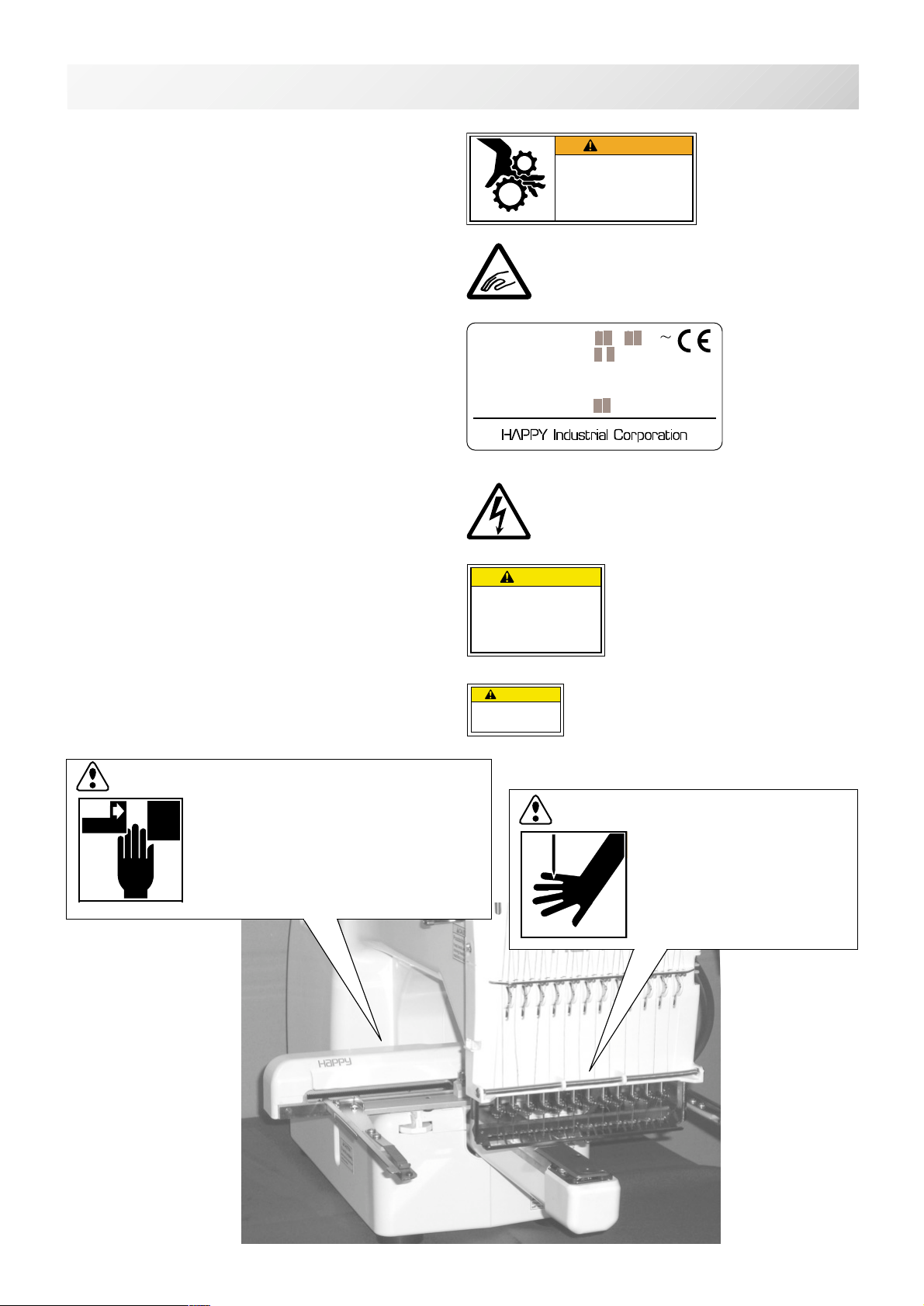
WARNING LABELS & THEIR LOCATIONS
1-2
Trapping hazard
Shut the cover when starting the machine.
Do not put hands in while the machine is running.
Trapping, Puncture, Cut hazard wherever this
label is found
Power Supply Voltage sticker
Risk of electrical shock and fire if the power
recommendations on this label are ignored!
Make sure that the power supply meets the exact
specifications as provided by the manufacturer.
Shock hazard on all electrical components
Injury risk on moving head(s)
Keep hands away from the moving heads while the
machine is running.
WARNING
Fear of serious injury.
Shut the cover when starting the
machine. Do not put hands in
while the machine is running.
VOLTAGE
AMPERE
PHASE SINGLE
FREQUENCY
POWER CONSUMPTION
CAUTION
Possibility of injury.
Keep hands away from the
moving heads while the
machine is running.
200-230V
1.1A
50/60Hz
220W
ES-HMF-5117-0
ES-HMF-5113-0
****
Laser beam (Class 1)
Do not stare into the beam.
CAUTION: Injury risk on frame and carriage
Keep hands away from the drive
frame while the machine is
running.
Catch a finger in the X-carriage.
CAUTION
Laser beam (Class 1)
Do not stare into the beam.
WARNING: Injury risk warning
for all needles
Keep fingers away from
the needles while
the machine is running.
-CS -6
1_2 K101
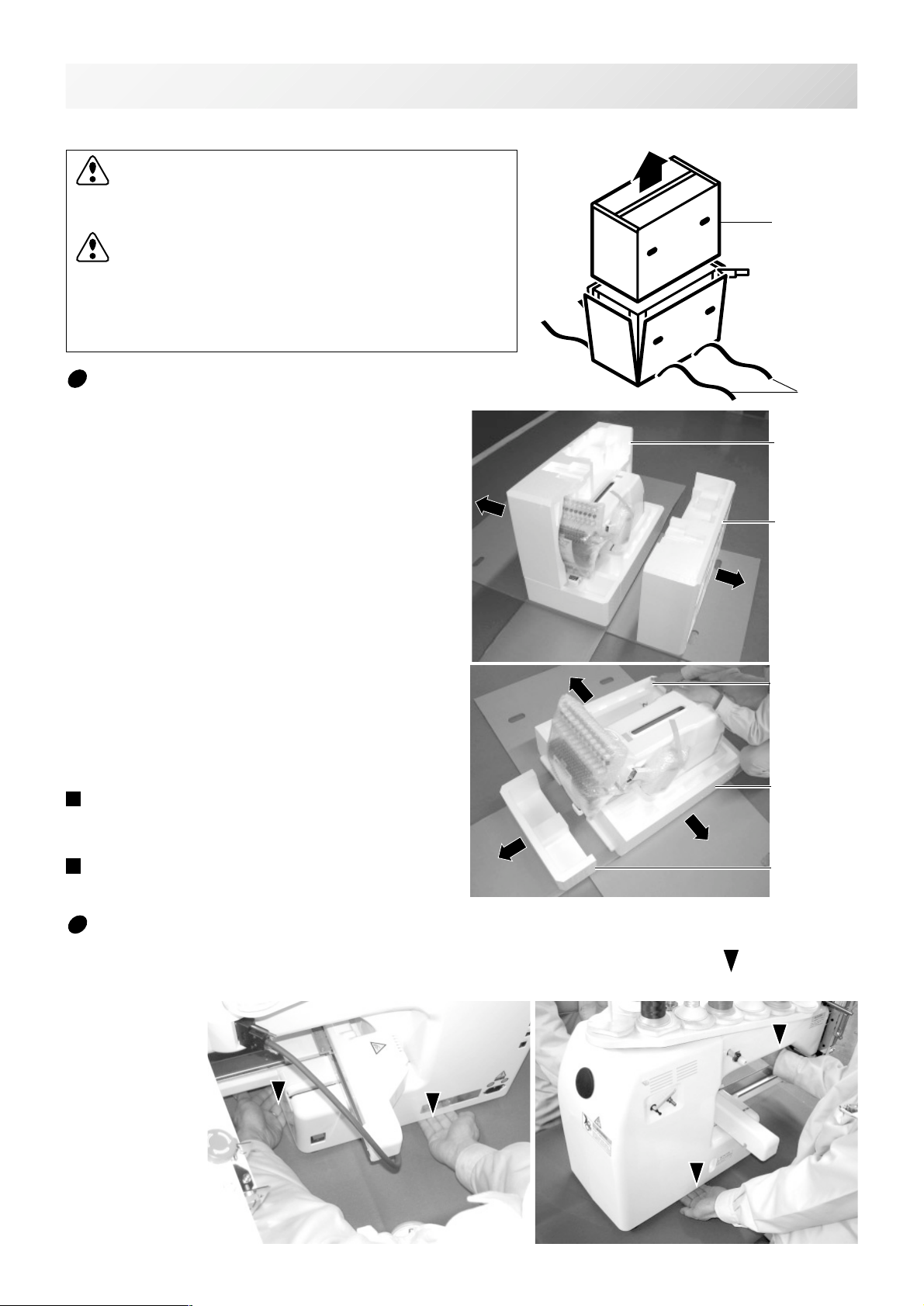
SETTING UP THE MACHINE
We recommend unpacking should be done where it has enough room.
CAUTION: To prevent accidents.
The machine is quite heavy for one person to carry.
Please use two persons when unpacking or carrying.
CAUTION: To avoid problems.
Make sure to hold bottom of the machine body when
removing from the box.
Do not hold any other place. (bed, moving head,
control box etc.).
2-1
Box (upper)
Remove the machine from box
1. Remove 2 straps from the carton.
2. Lift the box (upper) to remove.
3. Take out the accessories.
Refer to the next page.
4. Take out the styrene foam (right) and (left).
5. Take out the styrene foam (lower front),
(lower right), and (lower left).
Be careful not fall down the machine, tilt the
machine slightly when taking out the styrene
form (lower right) and (lower left).
6. Carry the machine to installation location.
Please keep those packing materials in
case of necessary for repair or other reasons.
Packing procedure is the reverse from
unpacking procedure.
Straps
Styrene
foam (left)
Styrene
foam (lright)
Styrene foam
(lower left)
Styrene foam
(lower right)
Styrene foam
(lower front)
How to carry machine
The unpacked machine should be carried by 2 person with the hand position at mark shown
in photos.
The person holding
the machine from
left side need to
hold the machine
arm by right hand.
Right side
Left side
-BD -5
2_1 K101

SETTING UP THE MACHINE
Placement of Accessories
Confirm all the accessories are contained when unpacking.
2-1b
Frame base
CD-ROM
CD-ROM (HAPPY Link Software)
Instruction manual
Embroidery sample
(Instruction manual, Parts list)
Embroidery frame (Round)
Embroidery frame (Square)
Thread stand
Thread guide bracket
Carriage
Thread stand felt (13 pcs)
USB cable
Power line cord ass'y
Tool set
Needle (10 pieces)
Fuse (6A)
Oiler
Sewing machine oil
Thread guide pillar (2 pcs)
Thread stand pin (13 pcs)
Wave washer (13 pcs)
-BD -6
2_1b K101
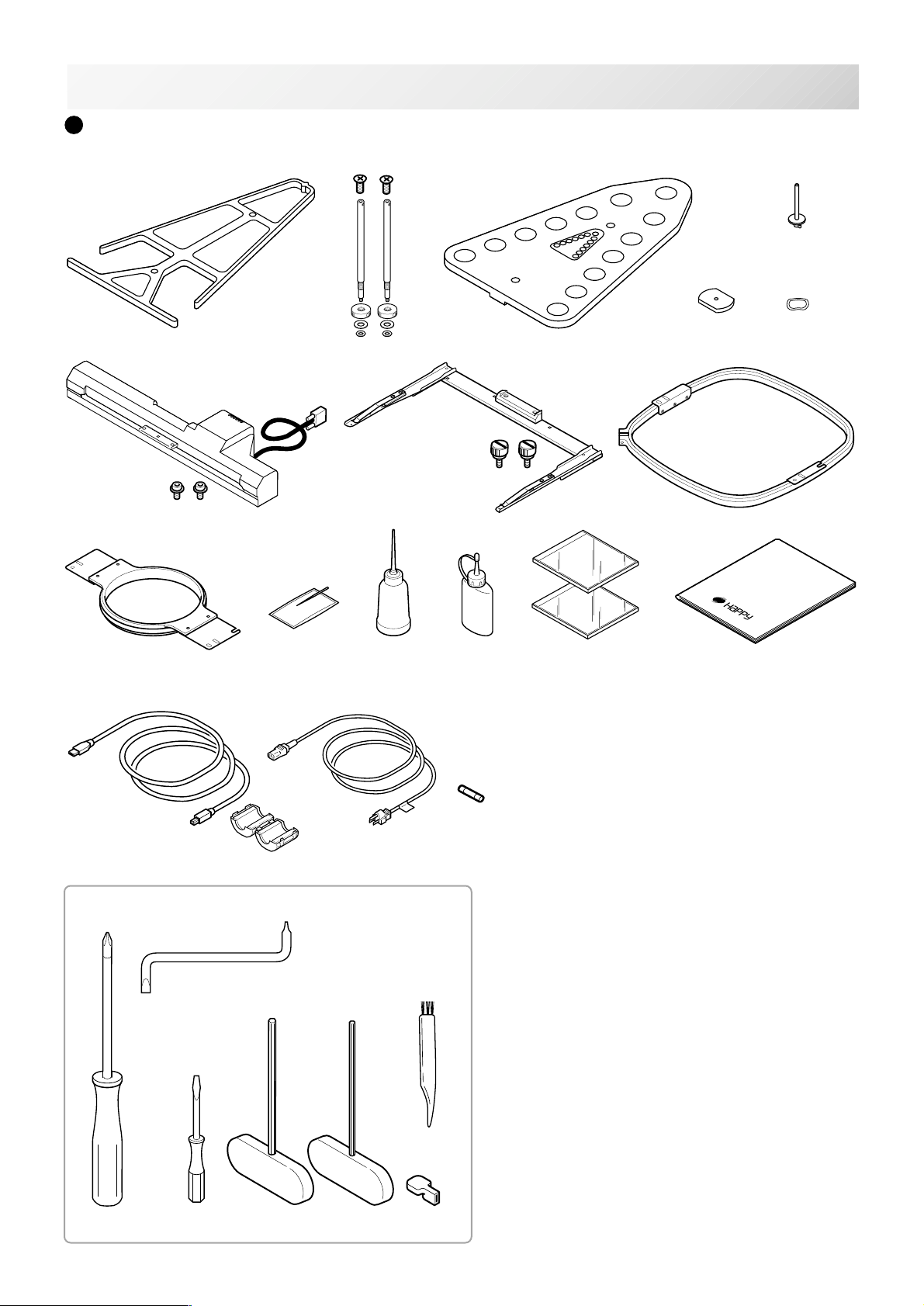
SETTING UP THE MACHINE
Accessories
Please confirm you have received the following.
2-2
5
Tools
21
1
78
10 11
17
27
20
22
23
12 13
18
24
2
25
26
463
14
15 16
1. Thread guide bracket
2. Thread guide pillar (2 pcs)
3. Thread stand
4. Thread stand felt (13 pcs)
5. Thread stand pin (13 pcs)
6. Wave washer (13 pcs)
7. Carriage
19
8. Frame base
9. Embroidery frame (square) PTA-32320-360
10. Embroidery frame (Round)
11. Needle (DB X K5) (10 pcs)
12. Oiler
13. Sewing machine oil
14. CD-ROM (Happy Link)
15. CD-ROM (Instruction manual, Parts list)
16. Instruction book (How to open the CD-ROM)
17. USB cable
18. Power line cord ass'y (A shape will be changed
depending on a destination)
19. Fuse (6A)
20. Off set screw driver
21. #2 (+) Screw driver
22. 2 mm (-) Screw driver
23. 3 mm hexagonal driver
24. 2.5 mm hexagonal driver
25. Brush
26. Manual lever
27. Clamp filter
PTA-15-360
9
-CS -7
2_2 L510
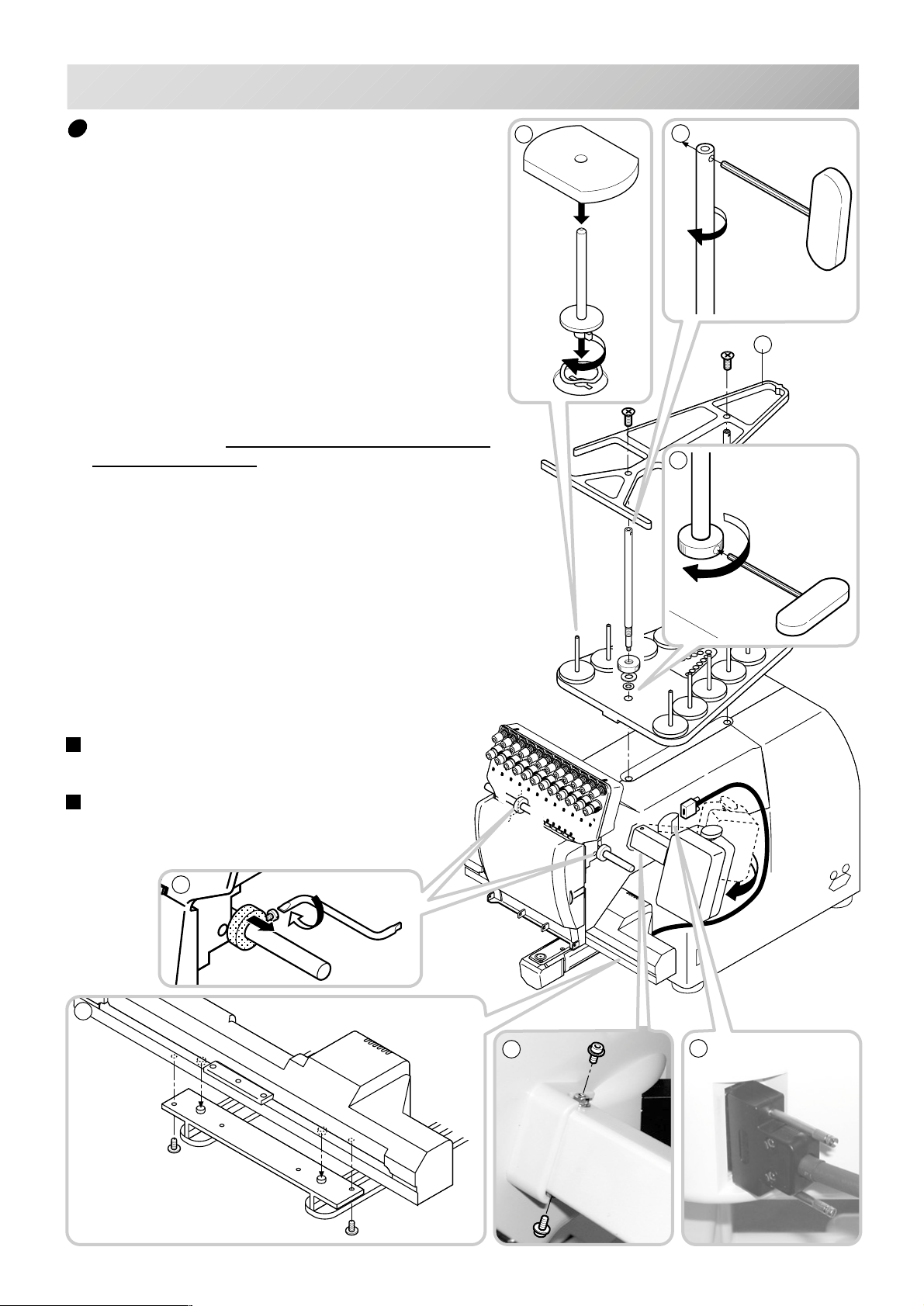
SETTING UP THE MACHINE
2-3
Assemble machine unit
1. Insert the thread stand pin with wave washer on the
thread stand by turning clockwise, Then insert thread
stand felt.
2. Put the thread stand on to the machine and insert the
thread guide pillar.
(set nut knob nut into the thread guide pillar and 2
washers)
Turn the thread guide pillar clockwise with a 3 mm
hexagonal driver until tight.
Turn the knob nut clockwise with a 3 mm hexagonal
driver until tight.
3. Install the thread guide bracket with supplied screws
(pan head screw M6 x 10 2 pcs).
4. Loosen the screw with a offset driver and remove the
red shipping collars that are equipped on the both side
of the guide bar. (
essary when packing.)
5. Put the carriage and carriage arm together with screw
(M4 X 8 2 pcs).
2 pins in the upper carriage arm will fit into holes on
the lower carriage.
6. Raise slowly the control box to the front then fix it with
2 supplied screws (M4 2 pcs).
7. Connect the cable of carriage to the machine with
fixed screw.
8. Install the arm for tubular embroidery. Please refer to
(page 6-1) "Installing and removing the frame base".
Or, Install the cap frame for the cap embroidery.
Please refer to (page 7-1) "Installing and removing the
cap drive frame".
Keep the shipping collars. It is nec-
1
2
3
2
When taking the machine apart in case of packing,
the process is opposite of assembling the machine.
Please do exactly the opposite way of assembling.
When packing the machine up for transportation,
be sure to select the sixth needle and fix it with
shipping collars on the both side of the guide bar.
4
5
6
7
-CS -8
2_3 I201
SETTING UP THE MACHINE
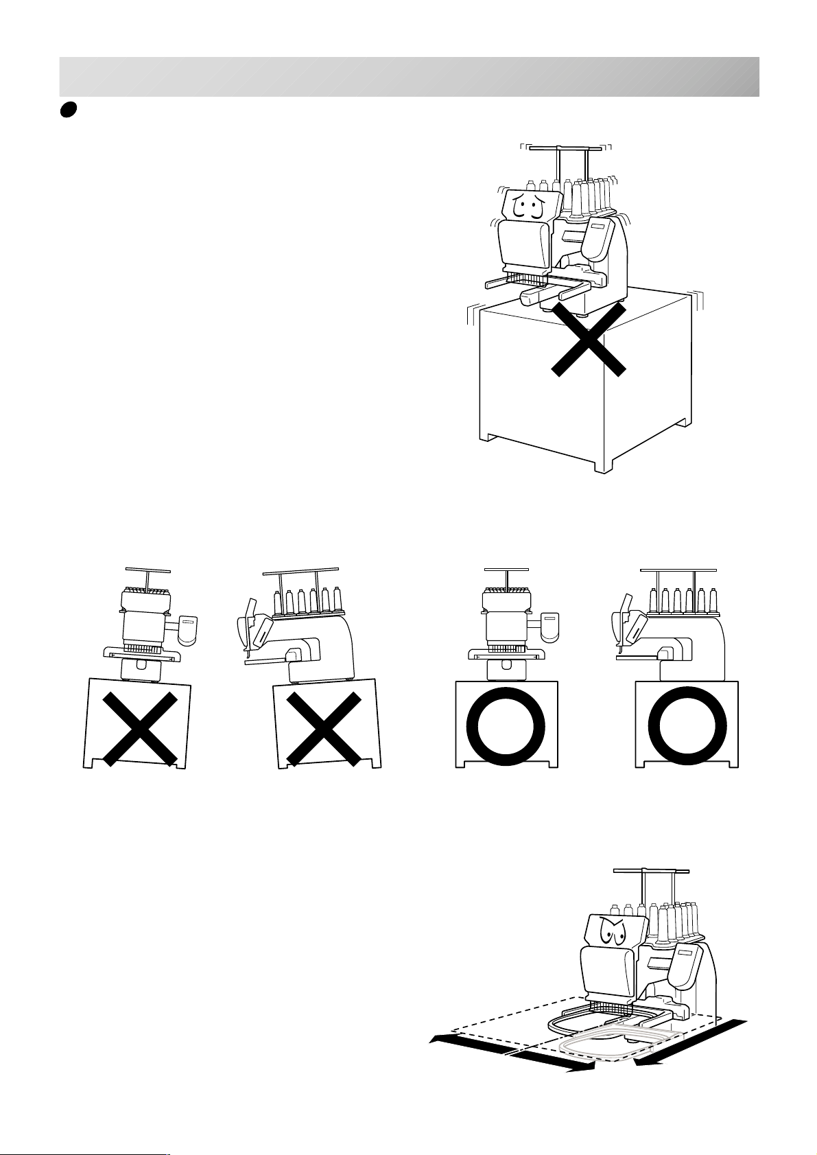
Machine installation
1. Please use a stout table to set the machine
on.
Please check for any shaking or excessive vibrating of the machine table when the machine is
running.
If you have a problem, Please use a stronger
table for the machine.
2-4
2. Please sit the machine level on the table.
3. Please be sure you have this much room
around your machine for it to move.
It is possible for the embroidery frame to hit you
and cause injury.
350 mm
350 mm
720 mm
-CS -7
2_4 D607
SETTING UP THE MACHINE
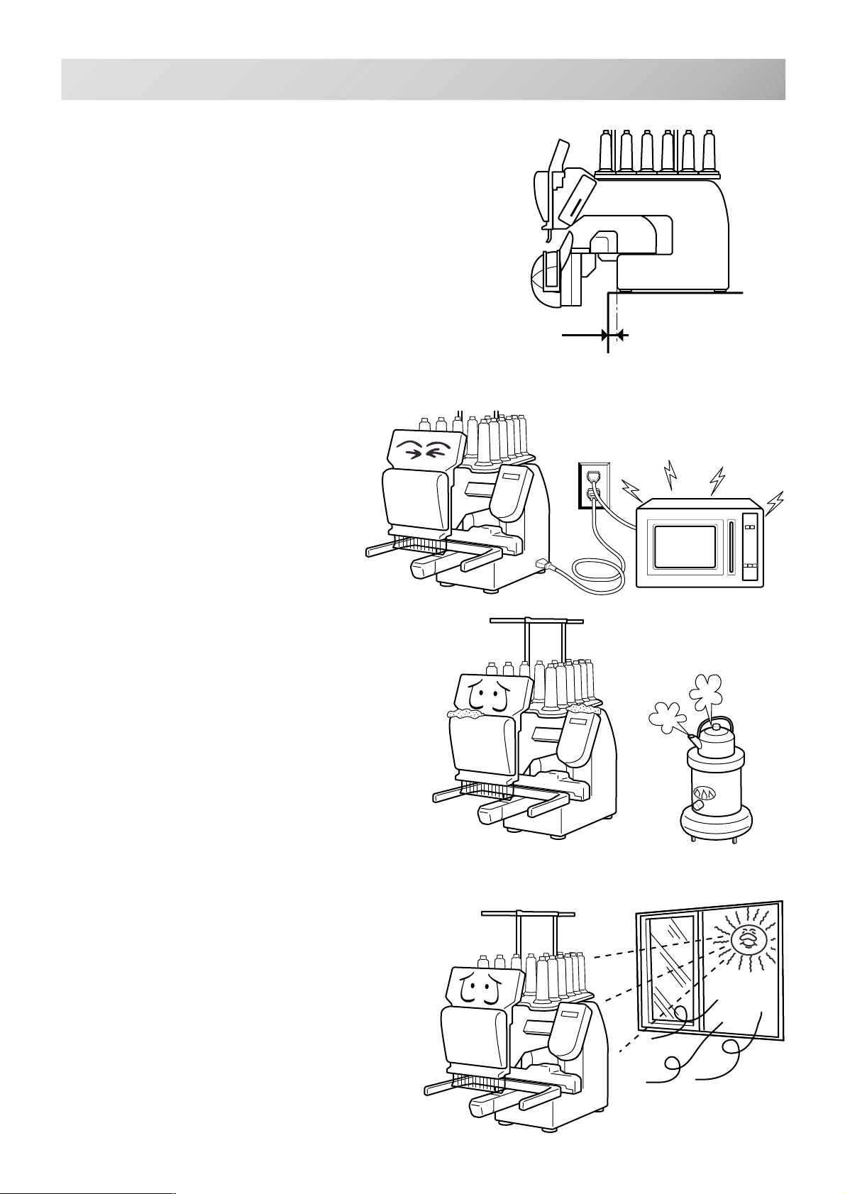
4. Please be sure you have this much room around
your cap drive for it to move.
Please machine on the table positioning like right side
drawing.
5. Please do not sit the machine near any
kind of other electric equipment
(Examples: Microwave or electric tool).
Has possible to wrong movement of the
machine.
2-5
0 ~ 10 mm
6. Please keep away from dusty and high moisture environments.
Has case of rusting or damaging.
7. Please do not sit the machine in direct
sunshine or windy locations.
Has case of rusting or damaging.
-CS -82_5 D607
SETTING UP THE MACHINE
2-6
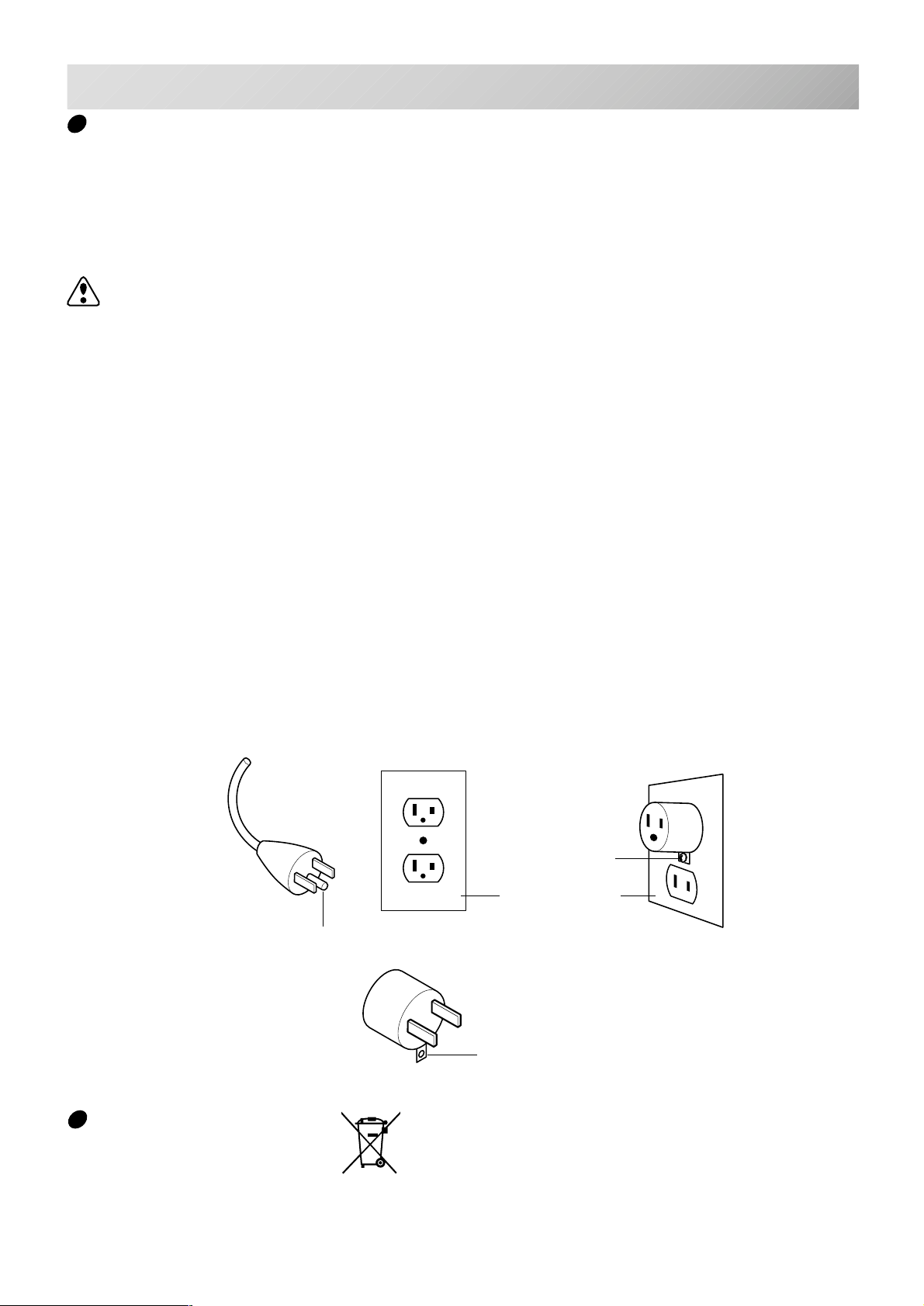
Grounding instruction (for type of 120V)
This product must be grounded. In the event of malfunction or breakdown, grounding provides a
path of least resistance for electric current to reduce the risk of electric shock. This product is
equipped with a cord having an equipment-grounding conductor and a grounding plug. The plug
must be plugged into an appropriate outlet that is properly installed and grounded in accordance
with all local codes and ordinances.
DANGER – Improper connection of the equipment-grounding conductor can result in a
risk of electric shock. The conductor with insulation having an outer surface that is green with or
without yellow stripes is the equipment-grounding conductor. If repair or replacement of the cord
or plug is necessary, do not connect the equipment-grounding conductor to a live terminal.
Check with a qualified electrician or serviceman if the grounding instructions are not completely
understood, or if in doubt as to whether the product is properly grounded.
Do not modify the plug provided with the product – if it will not fit the outlet, have a proper outlet
installed by a qualified electrician.
This product is for use on a nominal 120 V circuit, and has a grounding plug that looks like the
plug illustrated in sketch A in Figure. A temporary adaptor, which looks like the adaptor illustrated in sketches B and C, may be used to connect this plug to a 2-pole receptacle as shown in
sketch B if a properly grounded outlet is not available. The temporary adaptor should be used
only until a properly grounded outlet can be installed by a qualified electrician. The green colored rigid ear, lug, and the like, extending from the adaptor must be connected to a permanent
ground such as a properly grounded outlet box cover. Whenever the adaptor is used, it must be
held in place by the metal screw.
Grounding methods
Metal screw
Cover of grounded
outlet box
Grounding pin
A
Adapter
B
Grounding means
C
Disposal of a battery
A battery is had built-in to this embroidery machine.
When you dispose of a battery, according to each country or a method determined in each area,
please dispose appropriately.
-CS -11
2_6 I916
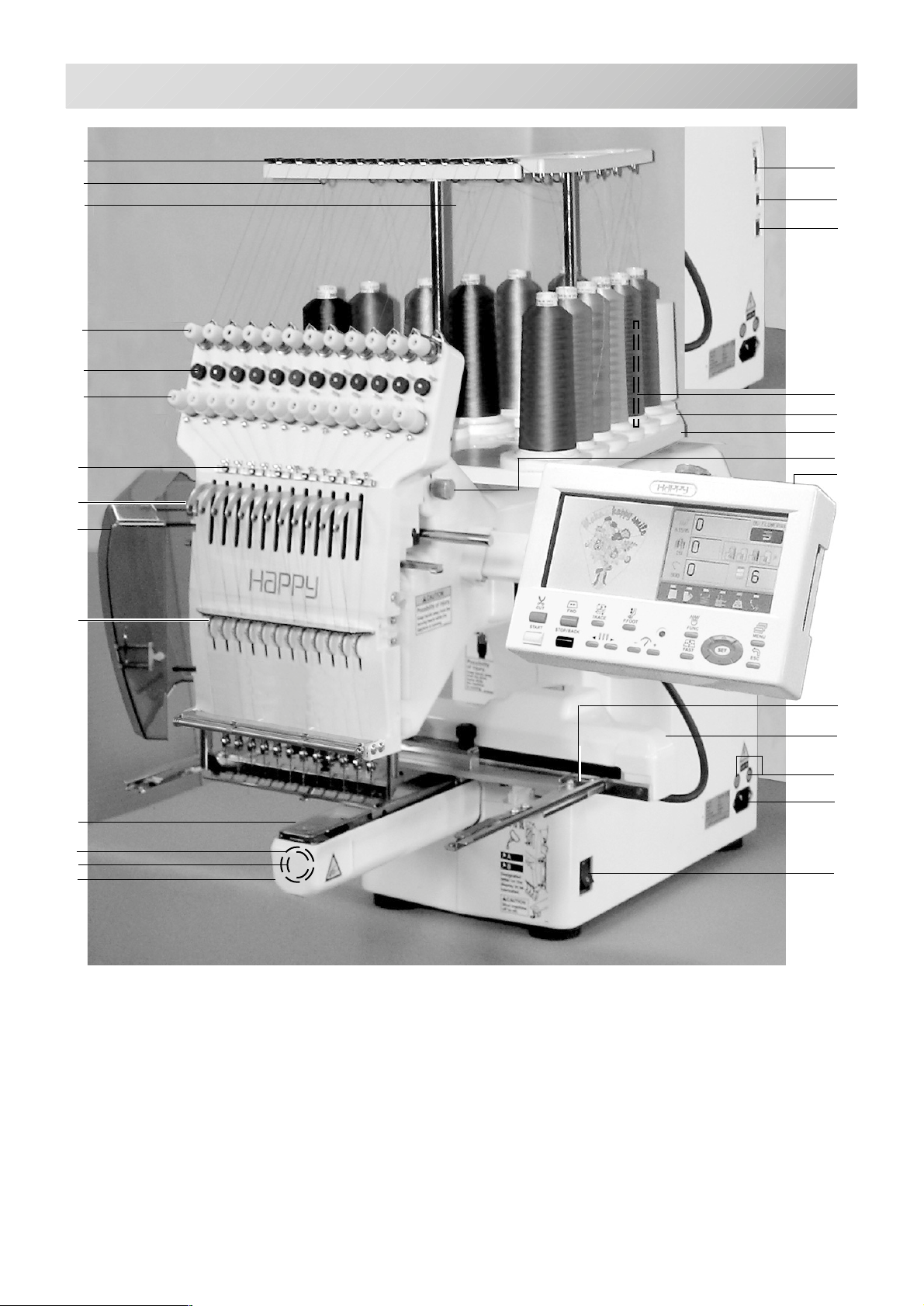
MAIN PARTS
3-1
14
13
12
11
10
9
8
7
6
20
21
22
15
16
17
18
19
5
4
3
2
1
1. Hook cover
2. Bobbin case
3. Hook
4. Needle plate
5. Thread check spring
6. Take-up lever cover
7. Take-up lever
8. Lower rectifier
9. Thread tension
10. Detecting roller
11. Minor thread tension
12. Thread guide support
13. Thread guide
14. Upper rectifier
15. Thread stand pin
16. Thread stand felt
17. Thread stand
18. Needle bar selection knob
19. Control box
20. Serial port
23
24
25
26
27
21. USB port (based on the USB)
22. LAN port
23. Frame base
24. Carriage
25. Fuse (6A)
26. Terminal box
27. Power switch
-BD -5
3_1 I201
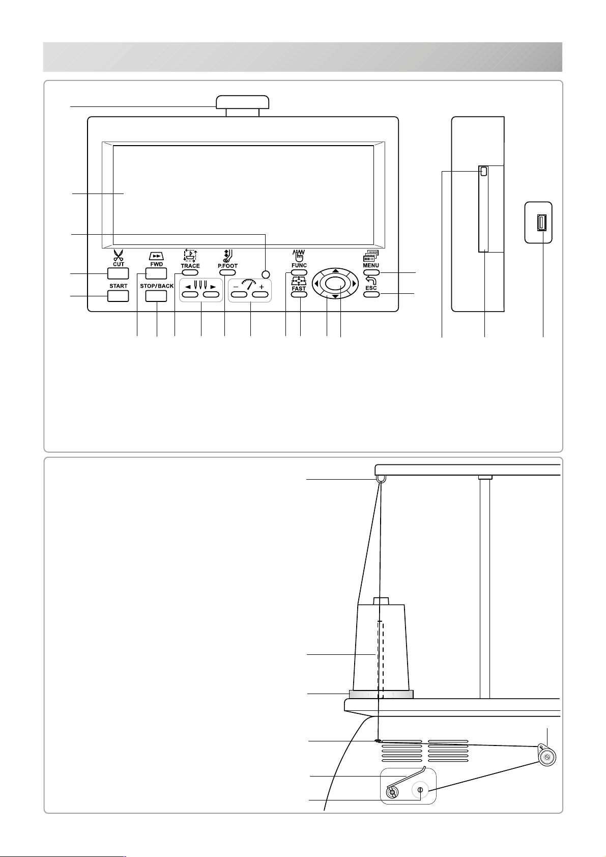
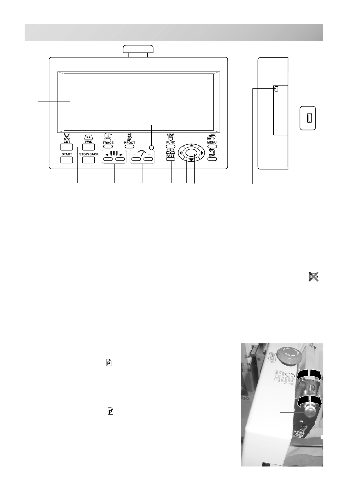
MAIN PARTS
CONTROL BOX
28
29
30
3-2
31
323334 35 37
28. Emergency stop
button
29. Display (L.C.D.)
30. Drive lamp
31. Forward button
32. Thread cut button
33. Start button
BOBBIN WINDING
(Option)
48. Upper Thread guide
49. Thread stand pin
50. Thread stand felt
51. Thread guide
52. Thread tension
53. Spindle
54. Lever
SET
36
38 3940 41 42
34. Stop button
35. Trace button
36. Pressure foot button
37. Needle change button
38. Speed control button
39. Function button
40. Fast button
48
43
44
45 46
41.
Arrow button (Up, Down, Left, Right)
42. Set button
43. Menu button
44. Escape button
45. Memory card eject button
46. Memory card slot
47. USB Memory port
47
49
50
51
54
53
52
-BD -53_2 H711
HOW TO READ THESE INSTRUCTIONS
3-3
The instructions in this manual have been formatted as follows:
Written instructions will be provided on the left side of the page while graphics depicting the
necessary steps are provided on the right.
Graphics on the far right will show the display after performing the steps indicated.
CAUTION: To prevent accidents.
This will appear for items related to your safety.
CAUTION: To avoid problems.
This will appear for items related to potential problems.
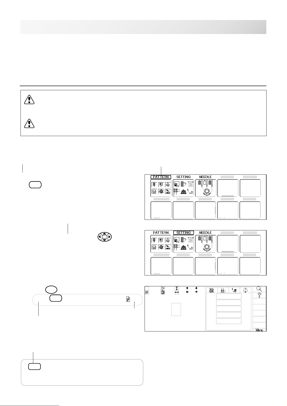
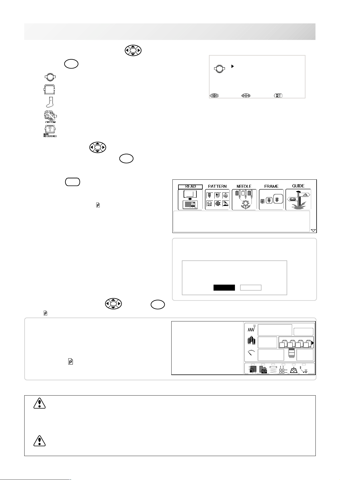
Order of operation
1. When the machine is stopped, Press the
MENU
.
AWords marked with a "*" are
explained in "EMBROIDERY
TERMS" at the end of this instruction manual.
2. Select desired *menu with
3. Press
SET
Press
to show the selected menu.
ESC
to return to the previous display. 3-3
.
Selected item
This indicates an
Indicates supplementary
explanation regarding a
given operation or action.
Operation key
additional explanation on an operation
elsewhere in the
manual for more
detail.
In the order of operation, this denotes
that the indicated keypress will cause
the display to change.
-CD -21
3_3 K101
MESSAGE
3-4
Below is a list of possible messages that may appear while operating the machine, along with
an brief explanation and suggested actions to take as a result.
Message
>>Stop Switch
Start button
Needle selection button
CAUTION: To prevent accidents.
The embroidery frame may move. Please
keep hands clear for your safety.
EGASSEM NOITANALPXE NOITAREPO EGAP
liootecalP
fogninaelC
koofyrator
fogninaelC
tucdaerht
efink
!evomemarF
hctiwSpotS>>
.ngised
dnE>>
.ngised
potSegnahC>>
?roloC>>
.detceles
kaerBdaerhT>>
dneecarT>>
.ecartngised
.efinkgnittucdaerht
.noitcnuf"tniop
SET
Set button
yalpsidehtnoretteldetangiseD
.detacirbuleboteudsi
ehtdnakoohyratorehtnaelC
ezingocerotevomlliwemarF
.noitisopemarflautcaeht
deppotssienihcamehT
sawnottubpotsehtesuaceb
ehtgnirediorbmeelihwdesserp
deppotssienihcamehT
ehtdehsinifsahtiesuaceb
uoyesuaceb,deppotsenihcaM
egnahcroloctapotS"desu
ehtesuacebdeppotsenihcaM
neebtonsahroloctxen
esuaceb,deppotsenihcaM
.nekorbdaerhtnibbobroreppu
deppotssienihcamehT
ehthtiwdehsinifsahtiesuaceb
.BroAyb
.nottub
.nottubtes
.noitisop
.gniwes
.yllacitamotua
.nottub
ehtninoitcurtsnihtiwnaelC
suoiverpehtotnruterdna
eldeentxentcelesesaelP
noitceleseldeenybrebmun
tratsehtsserpnehtnottub
.KOfinottubtratsehtsserP4-6
detacidninoitacolehtetacirbuL
niegapdetacidniehtotrefeR
tesehtsserpnehtlaunamsiht
ehtsserpnehtegapecnerefer
,nottubtesehtsserpuoynehW
evomlliwemarfyrediorbmeeht
emuserotnottubtratsehtsserP
,niagangisedwesothsiwuoyfI
nometidepoohylwenesaelp
.nottubtratssserp&enihcam
txenehttceleslliwenihcameht
gnirediorbmeemuserdnaroloc
rodaerhtreppudaerhtesaelP
sserpnehtdaerhtnibbobkcehc
.gniwesemuserotnottubtrats
1-32
2-32
5-3
,nottubtratsehtsserpuoynehW
C-7
-BD -6
3_4 H711
TURNING THE MACHINE ON
Do Not Show This Screen At Start.
MACHINE REFERENCE GUIDE : Choose a topic screen and press SET
: Exit
3-5
Basic mode is default setting of machine.
In case you want to use machine with Advanced mode, please enter machine setting and make
Operation mode "Advanced".
5-2
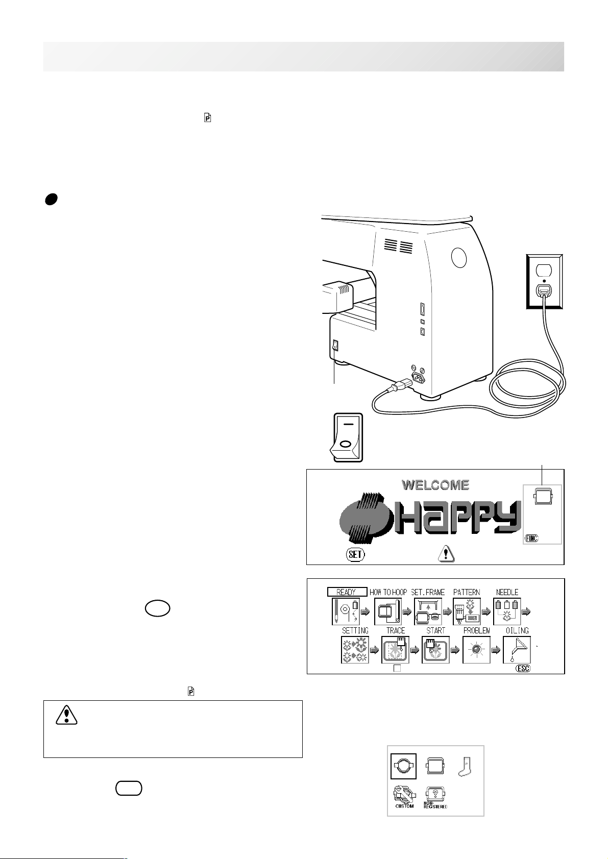
How to turn on the machine
1. Connect the power cord to the inlet on the
right side of the machine.
2. Connect the power plug to an electrical
outlet.
3. Turn on the power switch.
Please confirm the emergency stop button has
been released.
Push the power switch firmly so it will remain on.
4. In case you do not need to change frame
type, press the
After the carriage and frame move slightly, the
embroidery frame will return to the previous
position automatically.
Opening Guide is displayed. 3-D
In case the setting of Opening Guide is "OFF",
display jumps to step 7. 3-E
SET
button, go to step 7.
Power switch
ON
OFF
PRESS TO CONTINUE
Selected frame
PTA-*****
Y=***mm
X=***mm
:Change
KEEP CLEAR:CARRIAGE WILL MOVE!
CAUTION: To prevent accidents.
The embroidery frame and carriage will move.
Please keep hands clear for your safety.
In case you want to change frame type,
FUNC
press the
button.
-BD -10
3_5 K319
TURNING THE MACHINE ON
MAIN MENU : Chose a topic screen and press SET
5. Select the desired frame with and
press the
6. Press up/down of to select desired
SET
button.
: Tubular round frame
: Tubular square frame
: Sock frame
: User-defined frame
: Non registered
3-5b
No Name Size(YxX)
61 PTA-12 110mm
62 PTA-15 140mm
63 PTA-18 170mm
64 PTA-21 200mm
:Frame Type
:Frame Size
:Set Frame
type of frame and press the
The display returns to the view of Step 3.
7. Press the
Please proceed steps according to the instruction of "Basic mode" 4-8
In case you need to see explanation of item,
select desired item with and press
3-D
ESC
button.
SET
button.
SET
The READ screen is for importing designs from a flash card
Please ensure flash card is inserted first befor choosing this option.
In case previous design is not finished
completely and power machine off.
Sewing is stopped.
Do you wish to continue with this pattern?
Pattern Name :[ 12:BIRD ]
Yes No
.
If this menu appears on the screen
"Advanced mode" is selected.
To change to "Basic mode", please enter to
"MACHINE SETTING" and change mode to
"Basic mode".
To disconnect, switch the power switch to the off position, then remove plug from outlet.
DANGER: To reduce the risk of electric shock.
Never leave the machine unattended when plugged in.
Always unplug this machine from the electrical outlet immediately after use and before performing any maintenance on it.
WARNING: To reduce the risk of burns, fire, electric shock, or injury to persons.
Do not unplug by pulling on cord. To unplug, grasp the plug, not the cord.
5-2
-BD -11
3_5b K319

TURNING THE MACHINE ON
Display contrast
The contrast can be adjusted by following the procedure below.
3-6
1. When the machine stopped, press
and Select "CONTRAST" with .
SET
2. Press the
3. Adjust the contrast as desired by pressing
.
button.
MENU
4. Press the
The setting is fixed.
If you Press the
mode.
SET
.
ESC
you will return to drive
3_6 K101
-BD -12
TURNING THE MACHINE ON
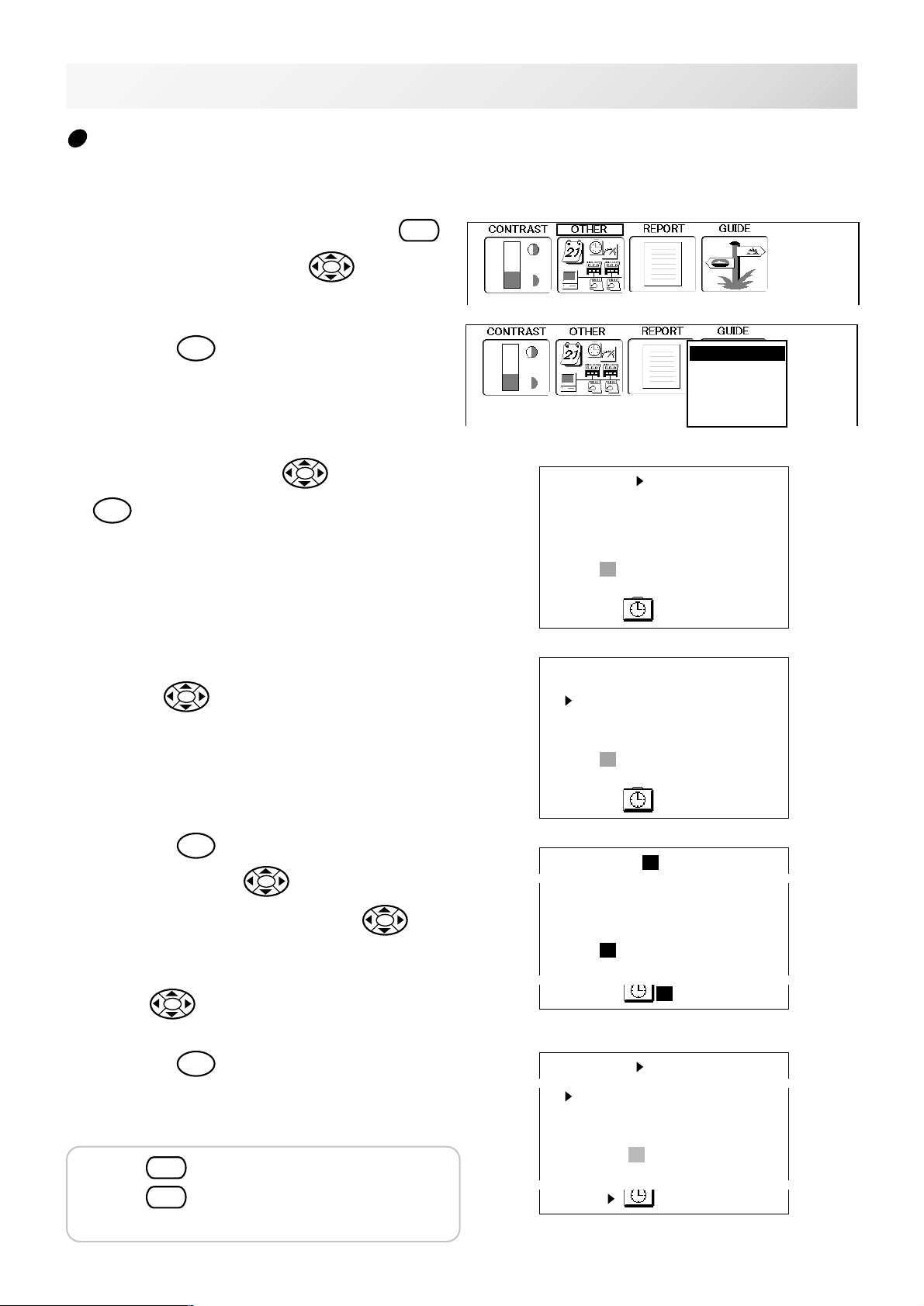
3-7
Calendar and clock setting
Setting the calendar and clock lets the machine advise when oiling and other maintenance is
scheduled to occur.
1. When the machine is stopped, press
MENU
and Select "OTHER" with .
2. Press the
3. Select "Calender" with
SET
.
Current year, month date and time is displayed.
SET
button.
and press
4. Select year, month date and time with up/
Calender
Network
System
Speed
Version
06/2005
SUN MON TUE WED THU FRI SAT
1 2 3 4
5 6 7 8 9 10 11
12 13 14 15 16 17 18
19 20 21 22 23 24 25
26 27 28 29 30
10:28:36
06/2005
down of .
5. Press the
Press right /left of
SET
button.
to select the set-
ting point, and press up/down of
select the number of year, month and time.
To select the date, press up/down and right
/left of .
6. Press the
The date is fixed.
Press
SET
.
ESC
to return to Menu mode.
to
SUN MON TUE WED THU FRI SAT
1 2 3 4
5 6 7 8 9 10 11
12 13 14 15 16 17 18
19 20 21 22 23 24 25
26 27 28 29 30
10:28:36
07/2005
SUN MON TUE WED THU FRI SAT
1 2 3 4
5 6 7 8 9 10 11
12 13 14 15 16 17 18
19 20 [21] 22 23 24 25
26 27 28 29 30
9:28:36
07/2005
SUN MON TUE WED THU FRI SAT
1 2 3 4
5 6 7 8 9 10 11
12 13 14 15 16 17 18
19 20 21 22 23 24 25
26 27 28 29 30
Press
mode.
ESC
once again to return to Drive
9:28:36
-BD -13
3_7 K101

THE CONTROL BOX
3-8
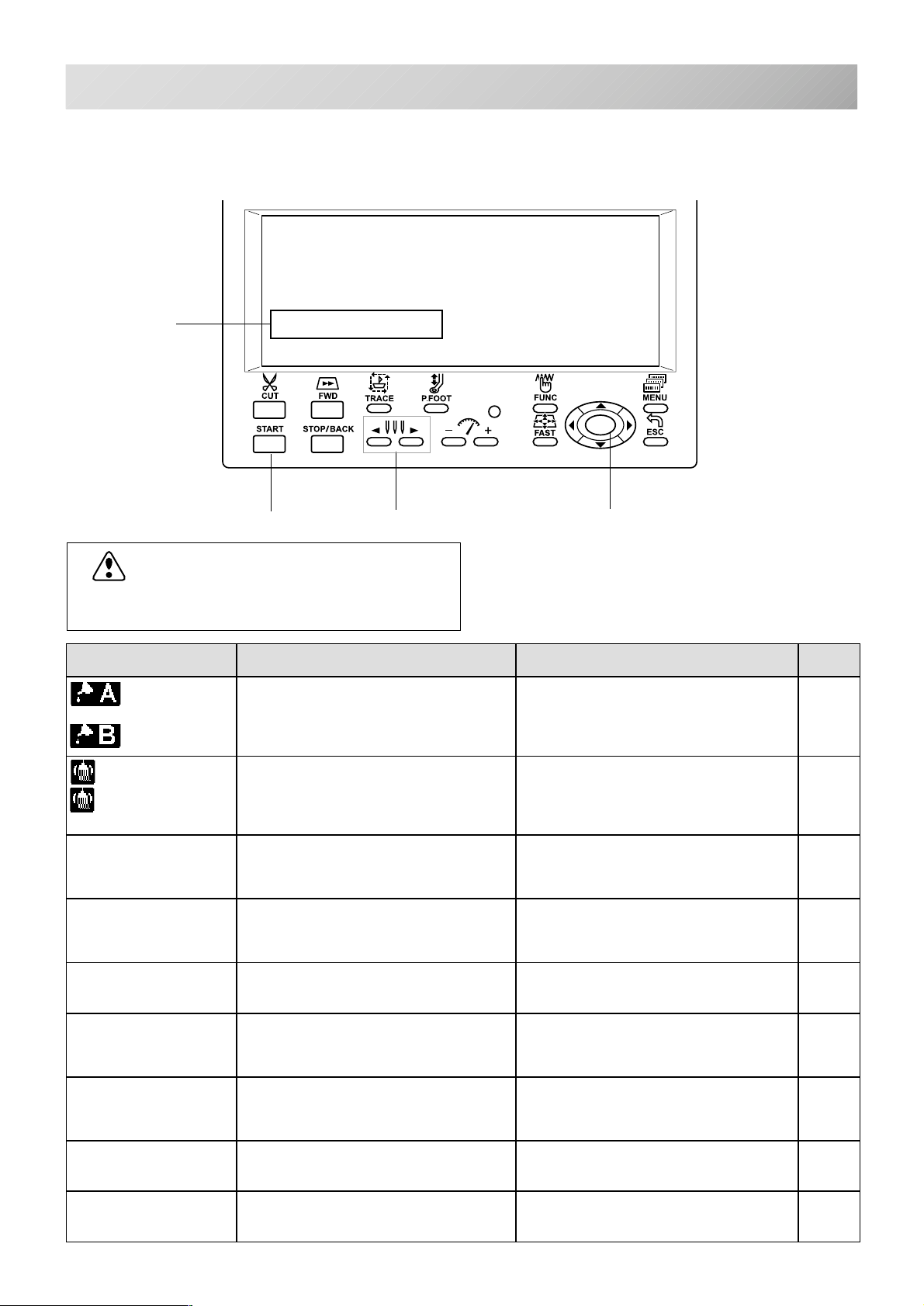
A. Emergency stop
A
button
When pressed , the
power is switched off
and the machine
stops immediately.
The emergency
button locks when
pressed.
To unlock, turn the
emergency button to
the right
(Arrow direction) then
release. The button
will
unlock.
Use this button only
for emergency.
B
C
D
F
E
G
B. Display
Shows the embroidery design name, the number of
the current needle and other machine generated
messages.
C. Drive lamp
Green ..........Machine ready to sew.
Main menu also accessible by
pressing MENU, which causes menu
to display.
Red .............Machine has detected an error.
An error number will be shown on
the Display. 24-1
Blinking red .Indicates the upper thread has
broken or the Bobbin thread has run
out.
D. Thread trim button
The Machine will cut the upper and lower thread
when this button is pressed.
CAUTION: To prevent accidents.
If you Press the thread trim button, the needle
will penetrate the fabric. Please keep your
hands clear for your safety.
E. Forward button
Press once............... The frame moves forward
one stitch.
Press continuously... The frame will move forward
continuously.
Keep pressing.......... The button's function locks.
The frame will move forward
by 1 stitch continuously.
Push the “STOP” button to
stop it.
When you stop it, push stop
button.
HJ
IK
Pressing longer still.. Button's function will lock.
F. Start button
This button starts the machine.
When pressed, while the machine is running,
running, the machine will switch to “inching”.
(Super slow speed)
The Machine will return to the previous speed
when button is released.
If you use the inching function for an extended
length of time, the stitch quality may be influenced.
G. Stop button
This stops the machine.
When the STOP button is pressed while the Drive
Lamp is blinking (green color), the following will
take place depending on the manner pressed:
Press once................ Frame moves back one
Press continuously.... The frame will move back-
Keep pressing. ..........The button's function locks.
Keep pressing longer still...
SET
LM
O
N
The frame will move forward
by 10 stitches continuously.
Push the “STOP” button to
stop it.
When you stop it, push stop
button.
stitch.
wards continuously.
The frame goes back by 1
stitch at a time continuously. Push the stop button
again to stop it.
The button's function locks.
The frame goes back by 10
stitches at a time continuously. Push the stop button
again to stop it.
P
Q
-BD -14
3_8 H711
THE CONTROL BOX
A
B
C
3-9
D
F
G
E
HJ
KLMNO
I
H. Trace button
When pressed while at the beginning of design,
the embroidery frame moves following the outer
edge of the design. This allows you to compare
the design size and position against the frame
before sewing.
I. Pressure foot button
You can raise or lower the presser foot .
J. Needle change button
Moves the sewing head to the adjacent needle
in the direction of the arrows.
K. Speed control button
Press the + button to increase the machine sewing
speed and the - button to lower the machine speed.
The sewing speed is shown on the display.
L. Function button
Press the function button to execute each function
of embroidering.
M. Fast button
When you press this key while pressing frame
move key, frame movement speed increases.
You can make more slow frame speed in
"Machine settings" menu. 5-2
N. Arrow button (Up, Down, Left, Right)
The frame moves toward direction of the arrow
mark..
In the menu, select each item required by pressing
the arrow mark toward the right direction.
You can change direction to opposite side in
" Machine settings" menu. 5-1
O. Set button
By pressing Set button, you can execute each
function in the menu and other settings.
Indicate target design on LCD panel when nonshowing design.
If you press this key and hold, re-display your target
design.
SET
P
Q
R
ST
P. Menu button
Displays the function menu for the machine settings and the design set-up.
Q. Escape button
Press ESCAPE button when you stop or cancel the
settings selected.
R. Memory card eject button
Press this button to take out the memory card.
Do not try to take out the memory card when
is displayed on the LCD display.
S. Memory card insertion slot
PCMCIA card socket for installing the memory
cards.
T. USB Mmemory port
USB Mmemory socket.
U. Knob screw
Loose the knob
screw and adjust
an angle of control
box, and tight the
knob screw for
fixing an angle of
control box.
U
-BD -153_9 DI701
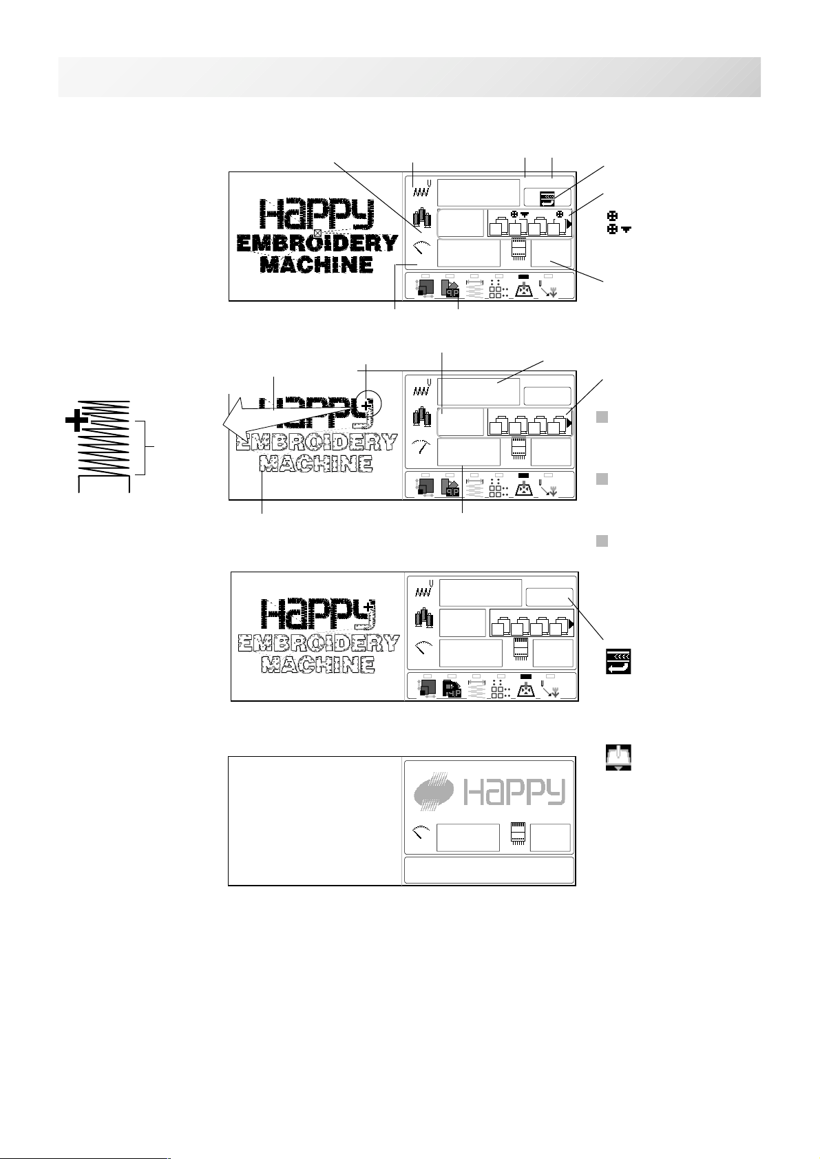
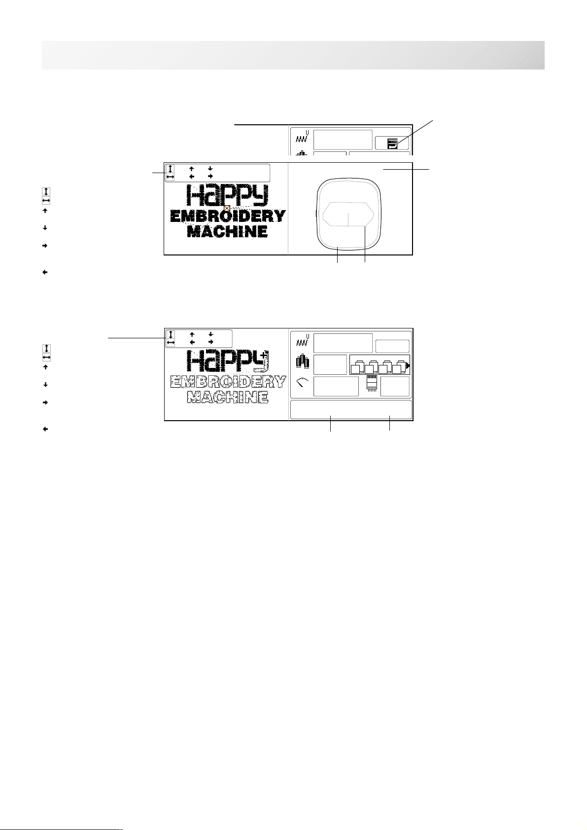
DRIVE MODE
Display example
When beginning an
embroidery
Current *Color
change number
Stitches
of pattern
Memory # of
selected pattern
0
12345
5
23
0 3
600
3 8 10 7
Name of selected pattern
Top
19:HAPPYE
Needle number and color
: Color change stop
: Frame out
Currently-selected needle
3-A
Number of maximum repetitions set
While embroidering
+cursor indicates the
position of actual stitch
point.
Drawing of
next 100
stitch will
be shown.
Machine stopped
during embroidering
Display if the machine
has no design in
memory
Lamp above icon blinks when each function (Scale, Angle
The embroidered part
and the next embroidering part will be
colored.
The part which has not embroidered
will be shown in outline.
Pointer
/Convert, Width, Repeat, Auto origin and Off set) is set.
12345
23
600
12345
23
600
Color change number sewn up to now
Number of stitches sewn up to now
19:HAPPYE
2653
3
8 10 7 3
520 3
Stitch speed
19:HAPPYE
2653
3
8 10 7 3
0 3
Shift to left when color
change.
If a needle number is not
assigned to a Color
change number, the
default color will be
assigned automatically.
Sewing starts after
outline of entire pattern is
displayed if sewing is
started from "Top" position.
"+" cursor indicates the
position of actual stitch
point.
In the display, pattern is
filled with color reflecting
sewing progress.
Status
Top
This indicates that the
machine is ready to start
sewing from the "top"
memory position of the
pattern.
Frame out
This indicates that a
frame out is occuring.
1
600
-CR -25
3_A K101
DRIVE MODE
Display example
Display when manually moving the hoop (at TOP state)
0
12345
3-Ab
Top
19:HAPPYE
Size of pattern and distance
Height
Width
Size between start point
and the top of pattern
Size between start point
and the bottom of pattern
Size between start point
and the extreme right of
pattern
Size between start point and the extreme left of pattern
Y: Y-distance moved
X: X-distance moved
219( 109 109) Y: -234.5
123( 61 61) X: 123.8
***
Embroidery
area
[***mmx***mm]
****
Display when manually moving the hoop (at RUN state)
Size of pattern
Height
Width
Size between start point
and the top of pattern
Size between start point
and the bottom of pattern
Size between start point
and the extreme right of
pattern
Size between start point
and the extreme left of
pattern
219( 109 109)
123( 61 61)
2653
12345
3
23
0 3
600
X: -234.5 Y: 123.8
X-distance moved Y-distance moved
Selected frame
Outline of pattern
19:HAPPYE
8 10 7 3
(Indicates X and Y distance)
-CR -26
3_Ab K101
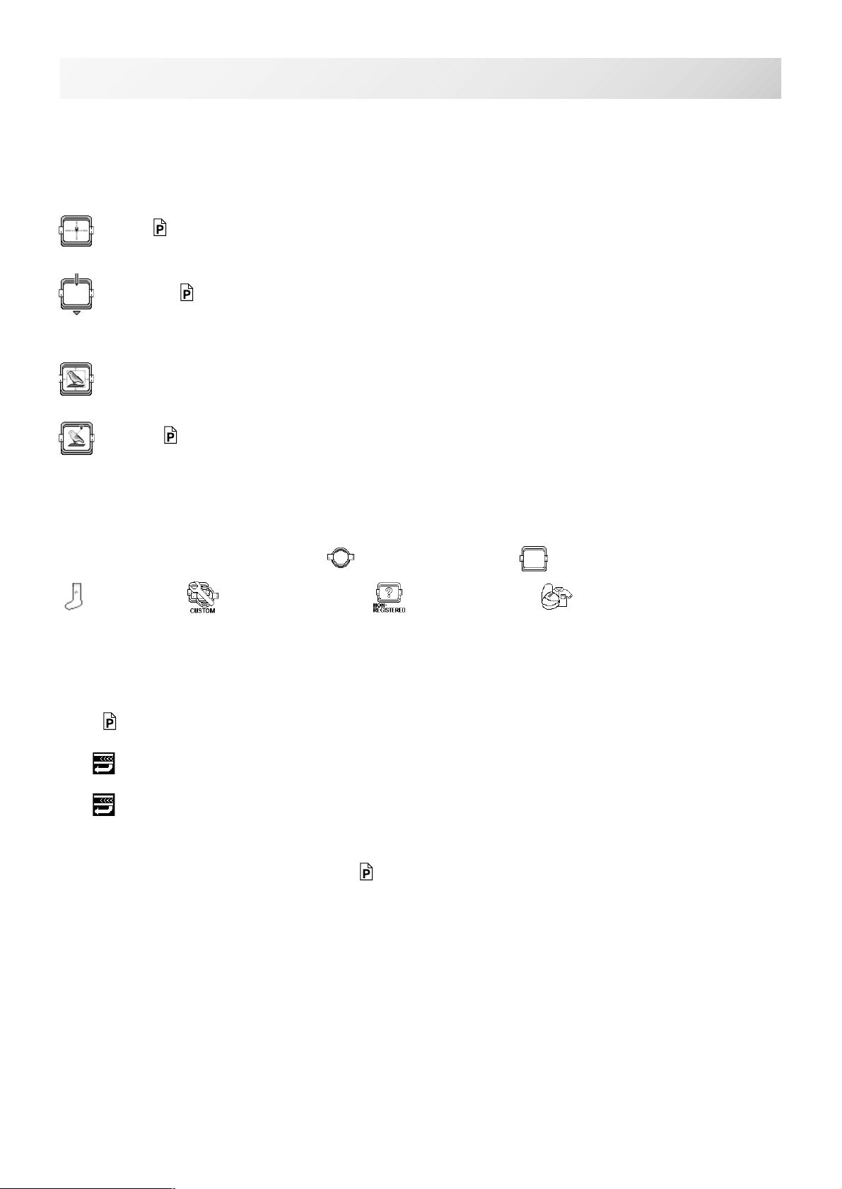
DRIVE MENU
The following functions are performed by in the drive menu.
3-B
Frame position
Selection the way of frame movement and Move frame.
Center 9-4
Moves the embroidery frame to the center automatically.
Frame out 5-2
Move frame to the front position which was set before.
It is convenience if hand work is required in the middle of embroider process.
Design centering
Move design to the center of frame.
Position 9-3
When sewing is interrupted in the middle of a design, this returns the frame to current sewing
position regardless of where frame may have been moved with the arrow keys after interrupt.
Frame type
Select appropriate frame type from Tubular round frame, Tubular square frame,
Sock frame, User-defined frame, Non registered or Cap frame etc.
0 Set (Registration of original point)
This enables to set original point manually.
Normally original point is registered automatically to the first stitch of the pattern data.
Top 9-4
This causes frame to return to the top of the pattern.
The
If this function is performed again, the action will be cancelled.
The light will turn off. The frame will then return to the previous position it was previously
stopped.
lights if you perform this function while in the middle of a design.
Original point return button 5-2
The frame returns to *original point of pattern, and position to start sewing returns to top of
pattern data.
Log-in, Log-out
Log-in is for the use of networking between the machine and PC.
Log-out is for disconnecting the machine from the network between PC.
Refer to the Network software instruction which correspond to this machine.
Turn-off
This will be used for turn off the machine when machine is networking.
Refer to the Network software instruction which correspond to this machine.
-BD -17
3_B K101
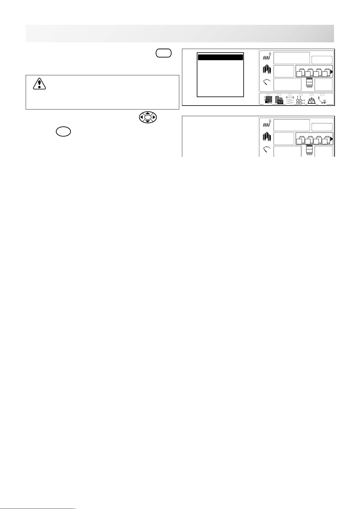
DRIVE MENU
3-Bb
1. When the machine is stopped, press
The drive menu will be shown.
FUNC
CAUTION: To prevent accidents.
The embroidery frame and carriage will move.
Please keep hands clear for your safety.
2. Select the desired function with and
press
SET
.
Drive menu will be cleared after execution of
selected function.
.
Frame position
Frame type
O Set
Top
Origin
Log-in
Turn-off
-BD -18
3_Bb K101
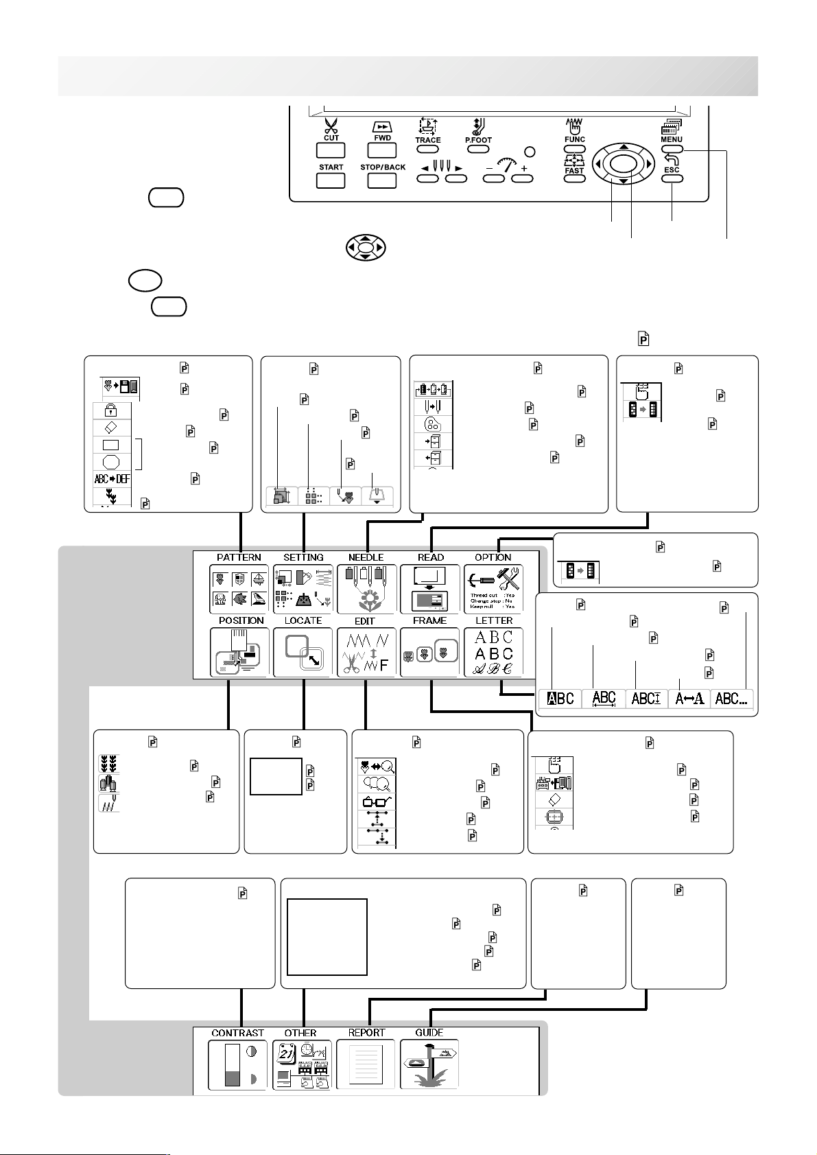
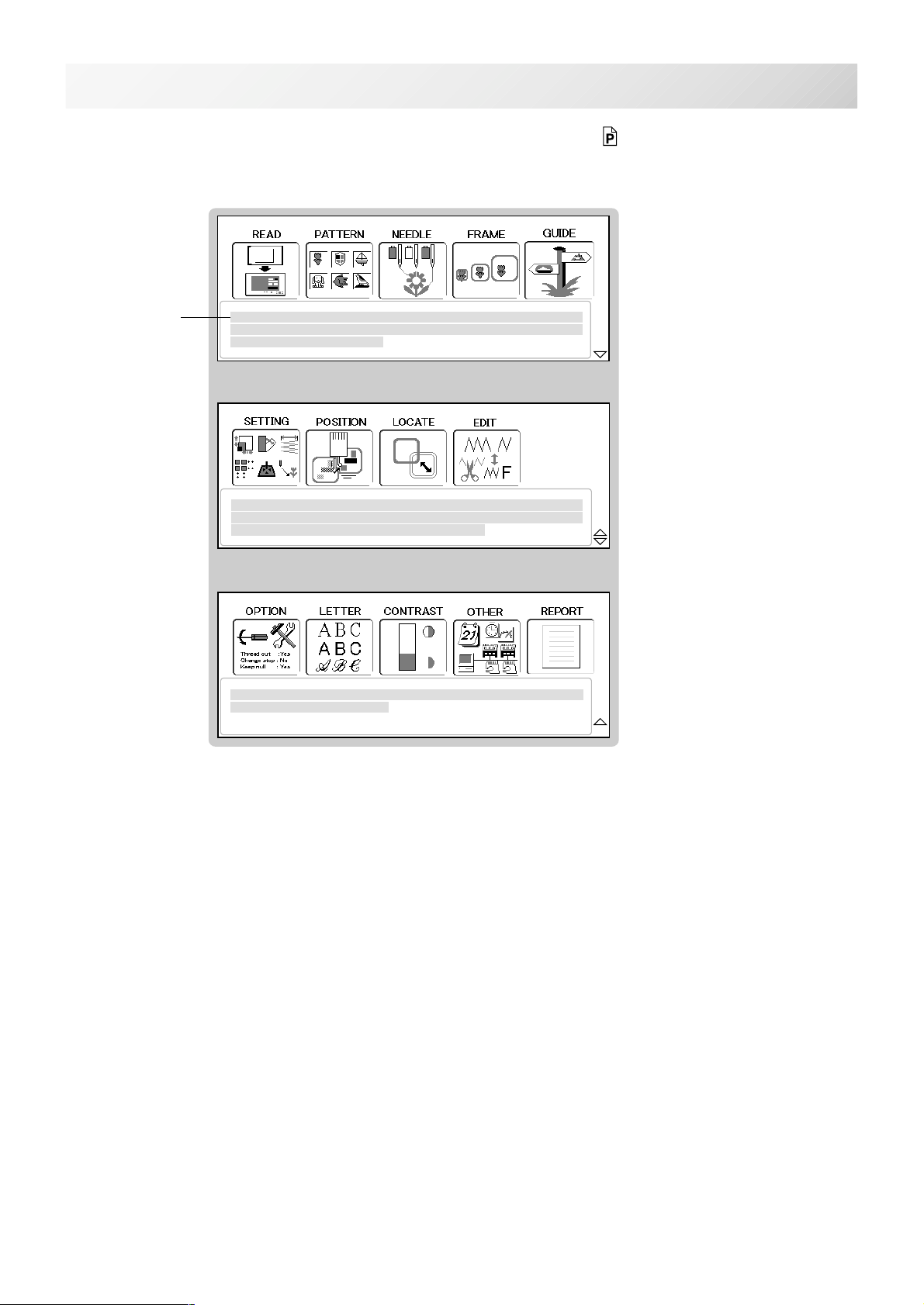
The diagram below describes
the layout functions accesed
from the main menu.
The main menu is accessed
3-CMENU
SET
by pressing
MENU
.
From here, any function can
then be selected with the up and down .
Pressing
If you Press
Memory pattern 5-A
SET
enters your choice.
ESC
from any point in the Menu mode, you will change to Drive mode.
Export 11-3
Lock of pattern data 11-1
Erasing 5-B
Trace type 11-2
Rename 11-5
Copy of pattern data
11-6
Setting
Scale
12-1
12-2
Repeat sewing
12-5
Offset
Frame out
12-8
12-E
Arrow button
Needle bar selection 13-1
Repetition of color group setting 13-7
Auto setting 13-2
Thread color
Color change data registration
Color change data read
13-3
13-6
Escape button
Set button
Reading 5-5
13-5
Machine settings
Initialization of setting
Menu button
Explanation page
Settings
Initialization of
setting
5-1
14-4
14-7
15-1
Position 16-1
Piece number
Move to color change 9-7
Go direct to stitch
Contrast of display 3-6
16-2
9-6
Locate 17-1
Entry
Return
17-2
17-3
Other settings
Calender
Network
System
Speed
Version
Data edit 19-1
Zoom in for the display
Zooming rate 19-5
Function code
Insert stitch
Erase stitch
Calendar and clock setting 3-7
Create network 22-1
Initializing of machine system 24-7
Initializing of machine speed
Version information 22-3
19-6
19-8
19-9
19-4
24-8
Letter 18-1
Letter selection 18-1
Line length
Frame confirmation 20-1
Change embroidery area
Reading frame data
Deleting user frame
Changing center point
Review and Create
18-2
Letter height selection
Font selection
Guide
18-2
18-3
20-4, 20-7
20-D
20-I
20-J
3-DReport 22-4
18-3
-BD -213_C K101
In Basic mode, explanation is shown under Icons on each menu. 4-8
MAIN MENU : Chose a topic screen and press SET
Explanation
MAIN MENU : Chose a topic screen and press SET
3-CbMENU
MAIN MENU : Chose a topic screen and press SET
-BD -203_Cb K101
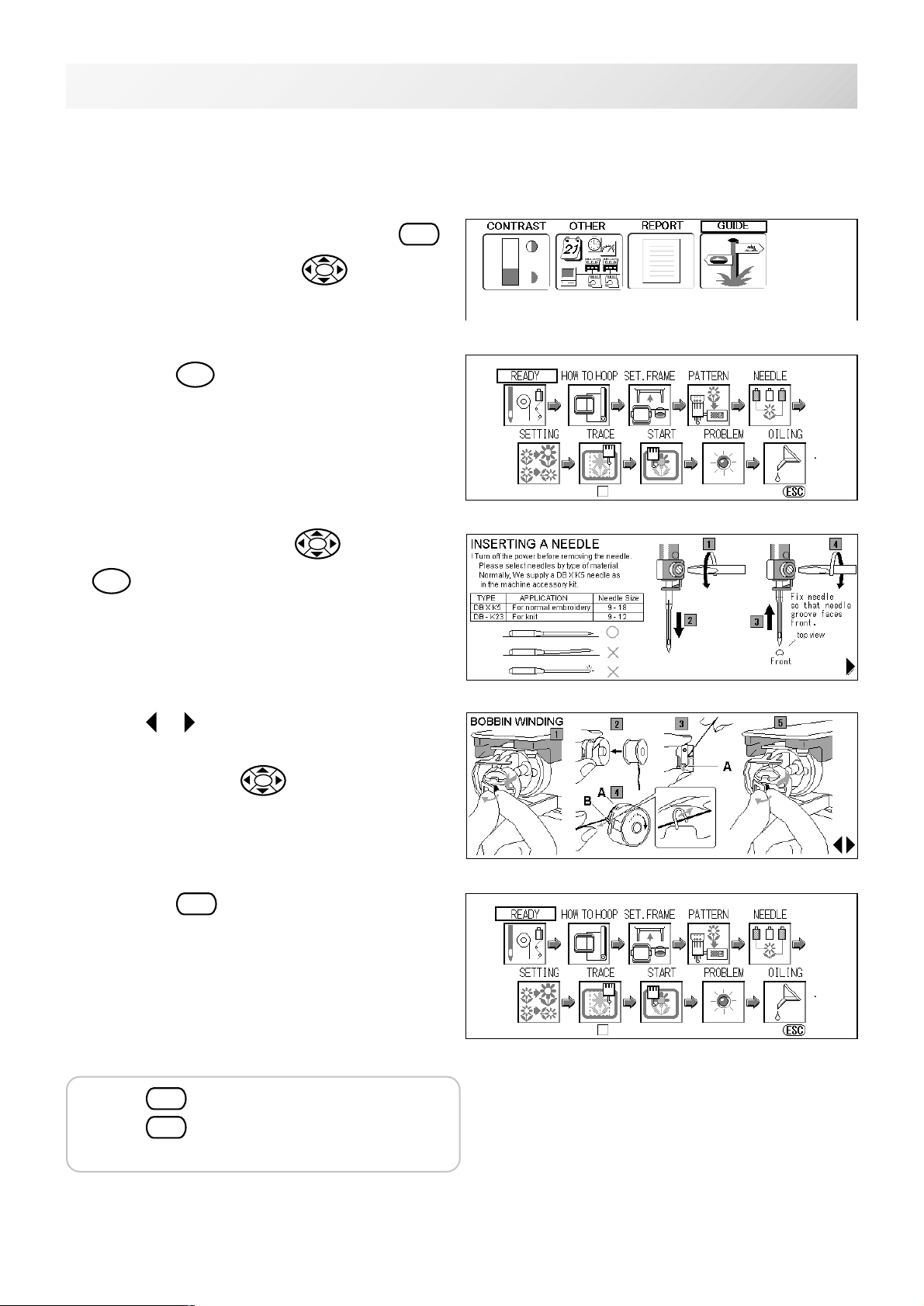
GUIDE
The GUIDE offers tips and step-by-step help for embroidering with the machine.
In each stage of embroidery operation there is an easy to follow guide available.
3-D
1. When the machine is stopped, press
and Select "GUIDE" with .
2. Press the
3. Select desired item with
SET
SET
button.
and press
.
MENU
MACHINE REFERENCE GUIDE : Choose a topic screen and press SET
Do Not Show This Screen At Start.
: Exit
4. When or is shown in the right lower
portion of the display, you can move to next
page by pressing
5. Press the
You will return to the guide menu.
Press
Press
ESC
ESC
ESC
.
to return to Menu mode.
once again to return to Drive
.
mode.
MACHINE REFERENCE GUIDE : Choose a topic screen and press SET
Do Not Show This Screen At Start.
: Exit
-BD -21
3_D K101
 Loading...