

Happy HCH Instruction Book
CHP401-16
INSTRUCTION BOOK
Program Ver. *1.40 ~
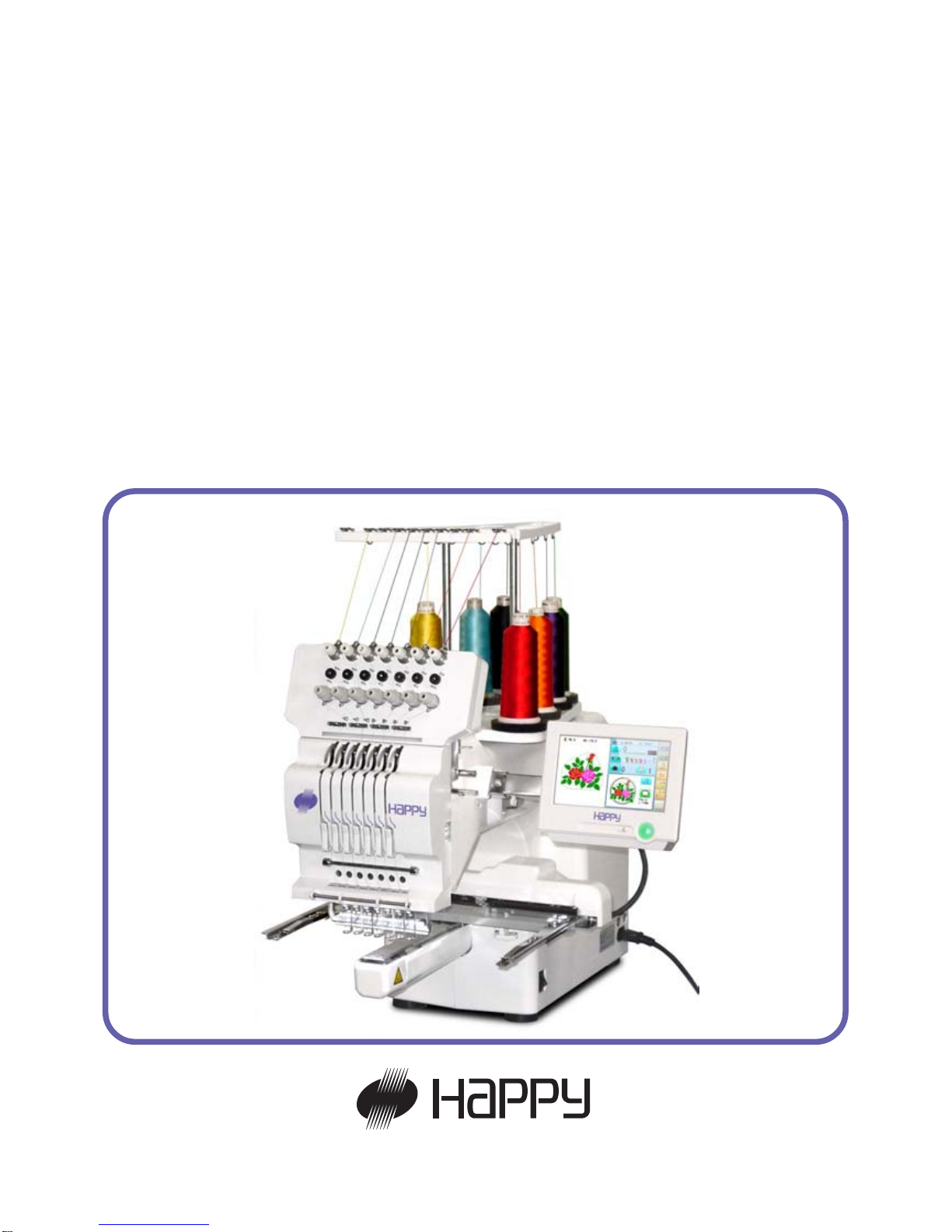
HCH
Computerized Compact Single Head Embroidery Machine
Original instructions


-SJ -3
INDEX
IMPORTANT SAFETY INSTRUCTIONS .. 1-1
WARNING LABELS & THEIR LOCATIONS .....
1-2
SETTING UP THE MACHINE
Remove the machine from box............... 2-1
Accessories ............................................ 2-2
Assemble machine unit .......................... 2-3
Machine installation ................................ 2-4
Grounding instruction ............................. 2-6
Disposal of a battery ............................... 2-6
MAIN PARTS ............................................ 3-1
THE CONTROL BOX ................................ 3-3
DRIVE MODE ........................................... 3-4
INSERTING A NEEDLE ............................ 4-1
SELECT NEEDLES AND THREADS....... 4-2
BACKING MATERIALS............................. 4-3
BOBBIN WINDING
Winding the bobbin ................................. 4-4
Removing the bobbin.............................. 4-5
Inserting the bobbin ................................ 4-5
Adjusting bobbin thread tension ............. 4-5
Inserting the bobbin case ....................... 4-5
THREADING THE MACHINE
How to thread upper thread .................... 4-6
HOW TO READ THESE INSTRUCTIONS and SCROLLBAR
4-8
DISPLAYING THE PATTERN IN SETTING MODE...
4-9
TURNING THE MACHINE ON
How to turn on the machine.................... 5-1
Calendar and clock setting ..................... 5-2
MESSAGE ................................................ 5-3
PREPARATION OF PATTERN DATA
Connecting to a PC ................................ 5-4
Reading embroidery pattern data from
the PC ..........................................................
5-4b
Read embroidery pattern data ................ 5-5
Reading pattern data .............................. 5-6
Selection of folders ................................. 5-9
How to select patterns from memory ...... 5-A
Erasing patterns from memory ............... 5-B
NEEDLE BAR SELECTION ...................... 5-E
SEWING WITH TUBULAR FRAMES
Installing and removing the frame base .. 6-1
How to hoop ........................................... 6-2
Putting the hoop on the machine ............ 6-3
Starting to embroider .............................. 6-4
CAP FRAME (OPTION)
Changing the needle plate...................... 7-1
Installing and removing the cap drive frame...
7-2
Normal cap frame ................................... 7-5
Wide cap frame ...................................... 7-8
Starting to embroider .............................. 7-B
ADJUSTING THE THREAD TENSIONS .. 8-1
SEWING
What to do if the thread breaks while sewing .
9-1
Stopping and resuming sewing .............. 9-1
Loss of power while embroidering .......... 9-2
Moving the hoop while embroidering and then returning to
the correct location (Position) .......................................
9-3
Moving back to the starting point (Origin) 9-3
Going back to the beginning of the design (Top) ....
9-4
Placing the design in the center of the selected
embroidery frame
(Center) ..................................
9-4
Rotating and mirroring designs (Convert) ..
9-5
Starting in the middle of a design (Position) ...
9-6
POSITION ALIGNMENT BY DEFINING 2 POINTS...
9-8
POSITION ................................................. 9-B
Piece number ......................................... 9-C
REGISTER ................................................ 9-D
Entry ....................................................... 9-E
Return ..................................................... 9-F
READING
Join ....................................................... 10-1
Pattern Read Settings .......................... 10-4
0_1 O212
0-1

-SJ -4
INDEX
0_2 O901
0-2
PATTERN
Locking pattern data ............................. 11-1
Trace type............................................. 11-2
Export ................................................... 11-3
Renaming patterns ............................... 11-5
Copying pattern data ............................ 11-6
Moving pattern data .............................. 11-7
Renaming folders ................................. 11-9
Sort ........................................................11-A
Thread break report ...............................11-B
Retrieving built-in design data .............. 11-C
Searching pattern data ......................... 11-D
NEEDLE BAR SELECTION .................... 12-1
Auto setting........................................... 12-2
Thread color ......................................... 12-4
Color change data registration ............. 12-6
Color change data read ........................ 12-7
Repetition of color group setting ........... 12-8
FRAME CONFIRMATION ....................... 13-1
Frame selection ...........................................
13-2
Adjusted for embroidery area ............... 13-4
User-defined frames (1 ~ 5).................. 13-7
User-defined frames (6 ~ 20).................13-A
How to change center point of frame (1 ~ 5, 6 ~ 20) .
13-H
Non registered ....................................... 13-J
PATTERN SETTINGS ............................ 14-1
Scaling .................................................. 14-2
Width adjustment .................................. 14-3
Angle .................................................... 14-4
Repeat sewing ...................................... 14-5
Auto origin ............................................ 14-7
Offset .................................................... 14-8
Frame out ............................................. 14-D
MACHINE SETTINGS............................. 15-1
LOCK STITCHES.................................... 15-5
LETTER .................................................. 16-1
QUEUE ................................................... 17-1
Alter and Execution .............................. 17-2
Needle bar selection and Pattern settings...
17-4
Registration of QUEUE setting ............. 17-6
Read QUEUE setting............................ 17-7
OTHER SETTINGS
Create network ..................................... 18-1
Version information............................... 18-3
Language.............................................. 18-5
Calibrate ............................................... 18-6
User maintenance mode ...................... 18-8
Report ..................................................... 19-1
GUIDE ..................................................... 20-1
SCREEN SAVER .................................... 21-1
i-CUSTOM............................................... 22-1
USER MANAGEMENT
Registration of administrator................. 22-3
Registration of user .............................. 22-6
Selection of user (Login)....................... 22-8
Selection of user (Login) at power ON . 22-9
LAYOUT ...................................................22-A
SPECIFICATIONS • MAINTENANCE
Specifications ....................................... 23-1
Oiling .................................................... 23-1
Cleaning of rotary hook
Cleaning of thread cutting knife ............ 23-2
ERRORS AND WHAT TO DO ................ 24-1
INITIALIZING OF MACHINE SETTINGS
Re-Initialization of machine system ...... 25-1
Initializing of machine speed ................ 25-2
HELPFUL HINTS .................................... 26-1
EMBROIDERY TERMS .......................... 26-2
BUILT-IN FONT LIST .............................. 26-3
BUILT-IN PATTERNS LIST .................... 26-4

-SJ -5
IMPORTANT SAFETY INSTRUCTIONS
1_1 N401
1-1
This electrical appliance is intended for household use.
When using an electrical appliance, basic safety precautions should always be followed, including the following.
Read all instructions before using this appliance.
DANGER - To reduce the risk of electric shock:
1. An appliance should never be left unattended when plugged in. Always unplug this appliance
from the electric outlet immediately after using and before cleaning.
WARNING
-
To reduce the risk of burns, fire, electric shock, or injury to persons:
1. Do not allow to be used as a toy. Close attention is necessary when this appliance is used
by or near children.
2. Use this appliance only for its intended use as described in this manual. Use only attachments recommended by the manufacturer as contained in this manual.
3. Never operate this appliance if it has a damaged cord or plug, if it is not working properly, if it
has been dropped or damaged, or dropped into water. Return the appliance to the nearest
authorized dealer or service center for examination, repair, electrical or mechanical adjustment.
4. Never operate the appliance with any air openings blocked. Keep ventilation openings of the
sewing machine and foot controller free from the accumulation of lint, dust, and loose cloth.
5. Never drop or insert any object into any opening.
6. Do not use outdoors.
7. Do not operate where aerosol (spray) products are being used or where oxygen is being
administered.
8. To disconnect, turn all controls to the off (“0”) position, then remove plug from outlet.
9. Do not unplug by pulling on cord. To unplug, grasp the plug, not the cord.
10.Keep fingers away from all moving parts. Special care is required around the sewing machine needle.
11.Always use the proper needle plate. The wrong plate can cause the needle to break.
12.Do not use bent needles.
13.Do not pull or push fabric while stitching. It may deflect the needle causing it to break.
14.Switch the sewing machine off (“0”) when making any adjustments in the needle area, such
as threading needle, changing needle, threading bobbin, or changing presser foot, etc.
15.Always unplug sewing machine from the electrical outlet when removing covers, lubricating,
or when making any other user servicing adjustments mentioned in the instruction manual.
SA VE THESE INSTRUCTIONS

-SJ -5
WARNING LABELS & THEIR LOCATIONS
1_2 M401
1-2
Trapping, Puncture, Cut hazard wherever this
label is found
Injury risk on moving head(s)
Keep hands away from the moving heads while the
machine is running.
Laser beam (Class 1)
Do not stare into the beam.
ES-HMF-5117-0
CAUTION
Keep hands away from the
moving heads while the
machine is running.
Possibility of injury.
Laser beam (Class 1)
CAUTION
Do not stare into the beam.
-SJ -7
SETTING UP THE MACHINE
2_1 N525
2-1
CAUTION: To prevent accidents.
The machine is quite heavy for one person to carry.
Please use two persons when unpacking or carrying.
CAUTION: To avoid problems.
Make sure to hold bottom of the machine body when
removing from the box.
Do not hold any other place. (bed, moving head,
control box etc.).
We recommend unpacking should be done where it has enough room.
Remove the machine from box
1. Remove 2 straps from the carton.
2. Lift the box (upper) to remove.
3. Take out the accessories.
Refer to the next page.
4. Take out the styrene foam (right) and (left).
5. Take out the styrene foam (lower front),
(lower right), and (lower left).
Be careful not fall down the machine, tilt the
machine slightly when taking out the styrene
form (lower right) and (lower left).
6. Carry the machine to installation location.
Please keep those packing materials in
case of necessary for repair or other reasons.
Packing procedure is the reverse from
unpacking procedure.
Straps
Box (upper)
Styrene foam
(lower front)
Styrene foam
(lower right)
Styrene foam
(lower left)
How to carry machine
The unpacked machine should be carried by 2 person with the hand position at mark shown
in photos.
Right side
Left side
The person holding
the machine from
left side need to
hold the machine
arm by right hand.
Styrene
foam (lright)
Styrene
foam (left)
-SJ -8
SETTING UP THE MACHINE
2-2
Placement of Accessories
Confirm all the accessories are contained when unpacking.
Frame base
CD-ROM (Instruction manual, Parts list)
CD-ROM (Happy Link Software)
Instruction manual
Embroidery frame (Round)
Embroidery frame (Square)
Thread stand
Thread guide bracket
Carriage
Thread stand felt (9 pcs)
LAN cable
USB cable
Power line cord ass'y
Tool set
Bobbin (1 pcs)
Needle (10 pieces)
Fuse (6A)
Oiler
Sewing machine oil
Thread guide pillar (2 pcs)
Thread stand pin (9 pcs)
Wave washer (9 pcs)
A
2_1b N525
-SJ -9
18
19
SETTING UP THE MACHINE
Accessories
Please confirm you have received the following.
2_2 O508
2-3
1. Thread guide bracket
2. Thread guide pillar (2 pcs)
3. Thread stand
4. Thread stand felt (9 pcs)
5. Thread stand pin (9 pcs)
6. Wave washer (9 pcs)
7. Carriage
8. Frame base
9. Embroidery frame (square) PTA-32320-360
10. Embroidery frame (Round)
PTA-15-360
11. Needle (DB X K5) (10 pcs)
12. Oiler
13. Sewing machine oil
14. CD-ROM (Happy Link)
15. CD-ROM (Instruction manual, Parts list)
16. Instruction book (How to open the CD-ROM)
17. LAN cable
18. Power cord ass'y (A shape will be changed ...
depending on a destination)
19. Fuse (6A)
20. Off set screw driver
21. #2 (+) Screw driver
22. 2 mm (-) Screw driver
23. 3 mm hexagonal driver
24. 2.5 mm hexagonal driver
25. Brush
27. Clamp filter
28. Stylus
28. USB cable
29. Bobbin (1 pc)
Tools
1
2463
7
8
9
11
12 13
15 16
20
21
22
23
24
5
25
14
27
28
17
26
3
29
10

-SJ -10
1
2
3
4
5
6
Assemble machine unit
1. Insert the thread stand pin with wave washer on the
thread stand by turning clockwise, Then insert thread
stand felt.
2. Put the thread stand on to the machine and insert the
thread guide pillar.
(set nut knob nut into the thread guide pillar and 2
washers)
Turn the thread guide pillar clockwise with a 3 mm
hexagonal driver until tight.
Turn the knob nut clockwise with a 3 mm hexagonal
driver until tight.
3. Install the thread guide bracket with supplied screws
(pan head screw M6 x 10 2 pcs).
4. Loosen the screw with a offset driver and remove the
red shipping collars that are equipped on the both side
of the guide bar. (
Keep the shipping collars. It is nec-
essary when packing.)
5. Put the carriage and carriage arm together with screw
(M4 X 8 2 pcs).
2 pins in the upper carriage arm will fit into holes on
the lower carriage.
6. Raise slowly the control box to the front then fix it with
2 supplied screws (M4 1 pcs).
7. Connect the cable of carriage to the machine with
fixed screw.
8. Install the arm for tubular embroidery. Please refer to
(page 6-1) "Installing and removing the frame base".
Or, Install the cap frame for the cap embroidery.
Please refer to (page 7-1) "Installing and removing the
cap drive frame".
9. Insert built-in stylus into the holder (slot) of control
box.
When taking the machine apart in case of packing,
the process is opposite of assembling the machine.
Please do exactly the opposite way of assembling.
When packing the machine up for transportation,
be sure to select the fourth needle and fix it with
shipping collars on the both side of the guide bar.
2_3 M401
2-4
SETTING UP THE MACHINE
7
2
9
-SA -10
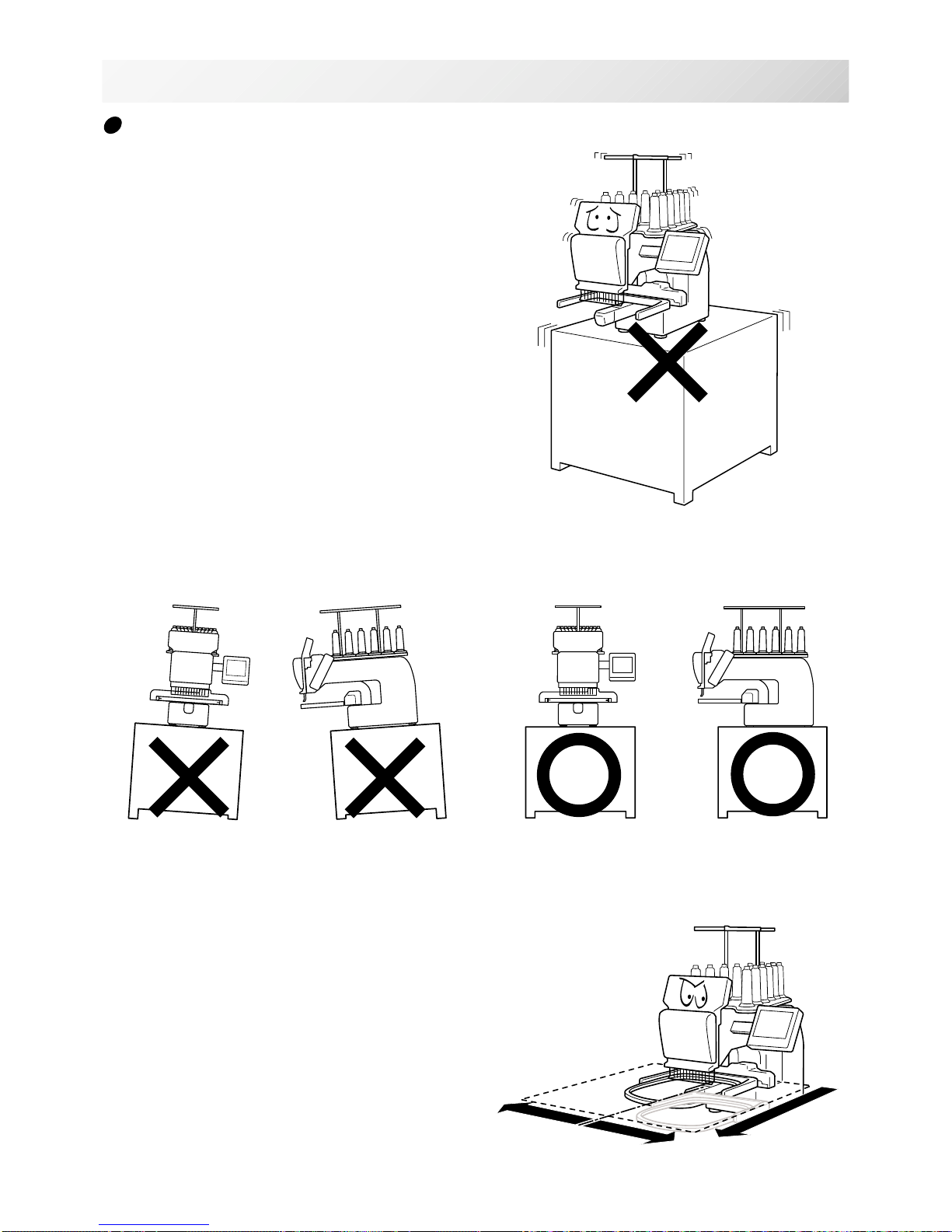
Machine installation
1. Please use a stout table to set the machine
on.
Please check for any shaking or excessive vibrating of the machine table when the machine is
running.
If you have a problem, Please use a stronger
table for the machine.
2_4 O728
2-5
SETTING UP THE MACHINE
350 mm
350 mm
720 mm
2. Please sit the machine level on the table.
3. Please be sure you have this much room
around your machine for it to move.
It is possible for the embroidery frame to hit you
and cause injury.
-SA -11
2_5 O728
2-6
SETTING UP THE MACHINE
0 ~ 10 mm
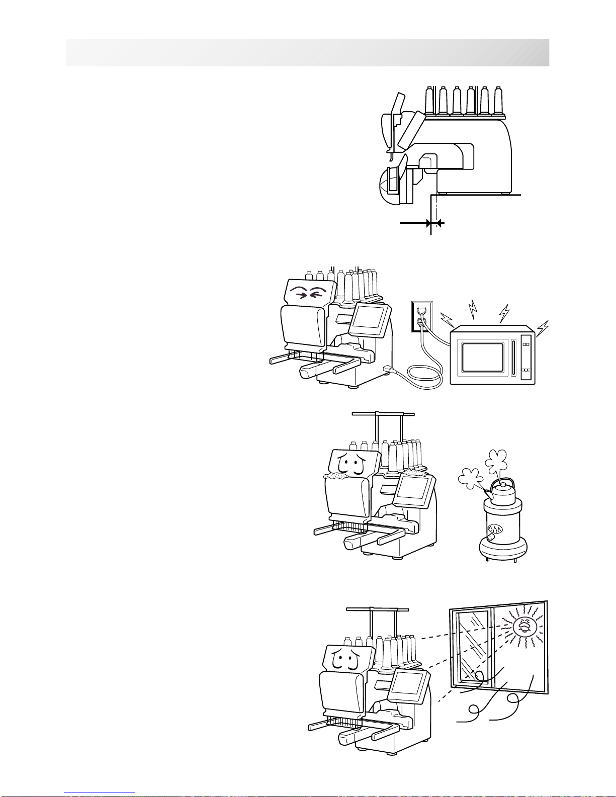
4. Please be sure you have this much room around
your cap drive for it to move.
Please machine on the table positioning like right side
drawing.
5. Please do not sit the machine near any
kind of other electric equipment
(Examples: Microwave or electric tool).
Has possible to wrong movement of the
machine.
6. Please keep away from dusty and high moisture environments.
Has case of rusting or damaging.
7. Please do not sit the machine in direct
sunshine or windy locations.
Has case of rusting or damaging.
-SJ -11
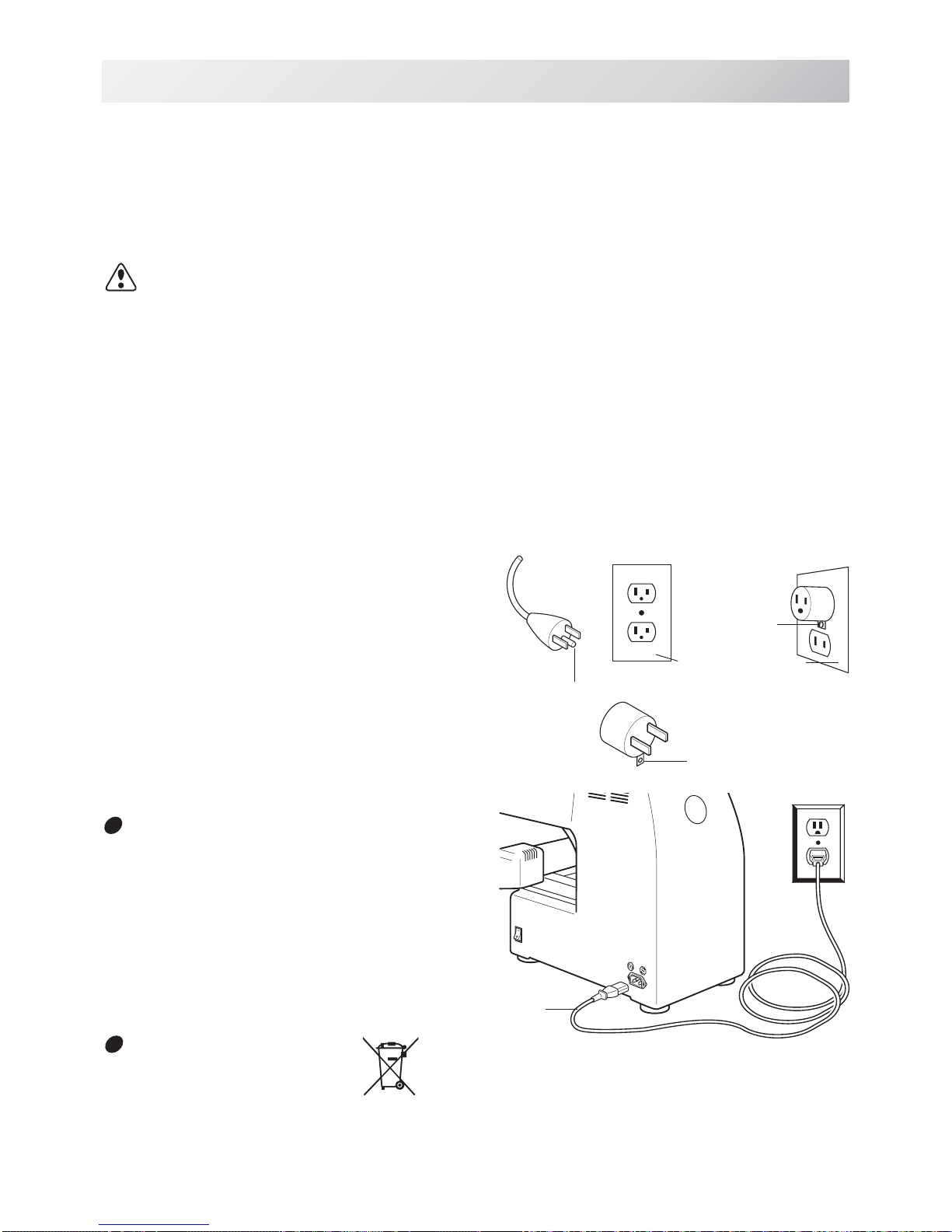
GROUNDING INSTRUCTIONS (for type of 120V)
This product must be grounded. In the event of malfunction or breakdown, grounding provides a
path of least resistance for electric current to reduce the risk of electric shock. This product is
equipped with a cord having an equipment-grounding conductor and a grounding plug. The plug
must be plugged into an appropriate outlet that is properly installed and grounded in accordance
with all local codes and ordinances.
DANGER – Improper connection of the equipment-grounding conductor can result in
a risk of electric shock. The conductor with insulation having an outer surface that is green with
or without yellow stripes is the equipment-grounding conductor. If repair or replacement of the
cord or plug is necessary, do not connect the equipment-grounding conductor to a live terminal.
Check with a qualified electrician or serviceman if the grounding instructions are not completely
understood, or if in doubt as to whether the product is properly grounded.
Do not modify the plug provided with the product – if it will not fit the outlet, have a proper outlet
installed by a qualified electrician.
This product is for use on a nominal 120 V circuit, and has a grounding plug that looks like the
plug illustrated in sketch A in Figure. A temporary
adaptor, which looks like the adaptor illustrated in
sketches B and C, may be used to connect this
plug to a 2-pole receptacle as shown in sketch B if
a properly grounded outlet is not available. The
temporary adaptor should be used only until a
properly grounded outlet can be installed by a
qualified electrician. The green colored rigid ear,
lug, and the like, extending from the adaptor must
be connected to a permanent ground such as a
properly grounded outlet box cover. Whenever the
adaptor is used, it must be held in place by the
metal screw.
2_7 NB25
2-7
SETTING UP THE MACHINE
Disposal of a battery
A battery is had built-in to this embroidery machine.
When you dispose of a battery, according to each country or a method determined in each
area, please dispose appropriately.
Metal
screw
Cover of grounded
outlet box
Grounding
pin
Grounding
means
Grounding methods
Adapter
A
B
C
Power cord
Damage of power cord
When you need to exchange power cord,
please be sure to use genuine product
designated by us.
-SJ -13
MAIN PARTS
3_1 NOC10
3-1
1. Hook cover
2. Bobbin case
3. Hook
4. Needle plate
5. Thread check spring
6. Take-up lever cover
7. Take-up lever
8. Lower rectifier
9. Thread tension
10. Detecting roller
11. Minor thread tension
12. Thread guide support
13. Thread guide
14. Upper rectifier
15. Thread stand pin
16. Thread stand felt
17. Thread stand
18. Control box
19. USB port
(Standard-B receptacle)
20. USB port
(Standard-A receptacle)
21. LAN port
22. Frame base
23. Carriage
24. Fuse (6A)
25. Terminal box
26. Power switch
1
2
3
4
5
7
8
9
10
11
12
13
15
16
17
18
22
23
24
25
26
14
20
21
19
6

-SJ -133_2 JN518
3-2
MAIN PARTS
BOBBIN WINDING
7
5
6
1
4
2
3
1. Upper Thread guide
2. Thread stand pin
3. Thread stand felt
4. Thread guide
5. Winder thread guide
6. Spindle
7. Lever
CONTROL BOX
3
4
1. Display (L.C.D.)
2. LAN port
3. Thread cut button
4. Start/Stop button
5
3
6
1
16
7
5. USB port (Standard-A receptacle)
6. USB port (Standard-B receptacle)
7. Stylus

-SJ -17
THE CONTROL BOX
3_8 NB25
3-3
1. Display (Touch screen)
Shows the embroidery design name, the number of
the current needle and other machine generated
messages.
Menu and keys in the display can be operated with
a finger or built-in stylus.
2. LAN port
You can connect PC with a LAN.
3. Thread trim button
The Machine will cut the upper and lower thread
when this button is pressed.
In case you press and keep (around 2 sec.), you
can cut only bobbin thread.
Blinking red . Indicates the upper thread has
broken or the Bobbin thread has run
out.
Red .............Machine is running.
Orange ........Machine has detected an error.
An error number will be shown on
the Display. 24-1
5. USB port (Standard-A receptacle)
USB memory socket.
USB mouse socket.
Menu and keys in the display can be operated with
a commercial USB mouse.
Press right mouse button to show a mouse pointer
in the display.
6. USB port (Standard-B receptacle)
Use this port to connect the machine with PC via
USB.
7. Stylus
Stylus can be used for pressing menu and keys in
place of fingers.
Most operation can be done by fingers. Stylus is
required for some operation such as calibration for
the touch panel LCD. 18-6
Insert a stylus into the holder (slot) of control box
when not used to prevent loss of the stylus.
CAUTION: To prevent accidents.
If you Press thread trim button, the needle will
penetrate the fabric. Please keep your hands
clear for your safety.
1
3
4
5
16
6
2
7
4. Start/Stop button
This button starts the machine.
When pressed, while the machine is running, the
machine will stop.
Green ..........Machine ready to sew.
Main menu also accessible by
pressing MENU, which causes menu
to display.
CAUTION
The touch screen can be operated by finger, but in some cases sensitivity of the screen will
be affected by condition of the finger.
In such cases, please use the fingertip or built-in stylus to hit small touch targets.
-SJ -18
3_4 O512
3-4
DRIVE MODE
Drive key
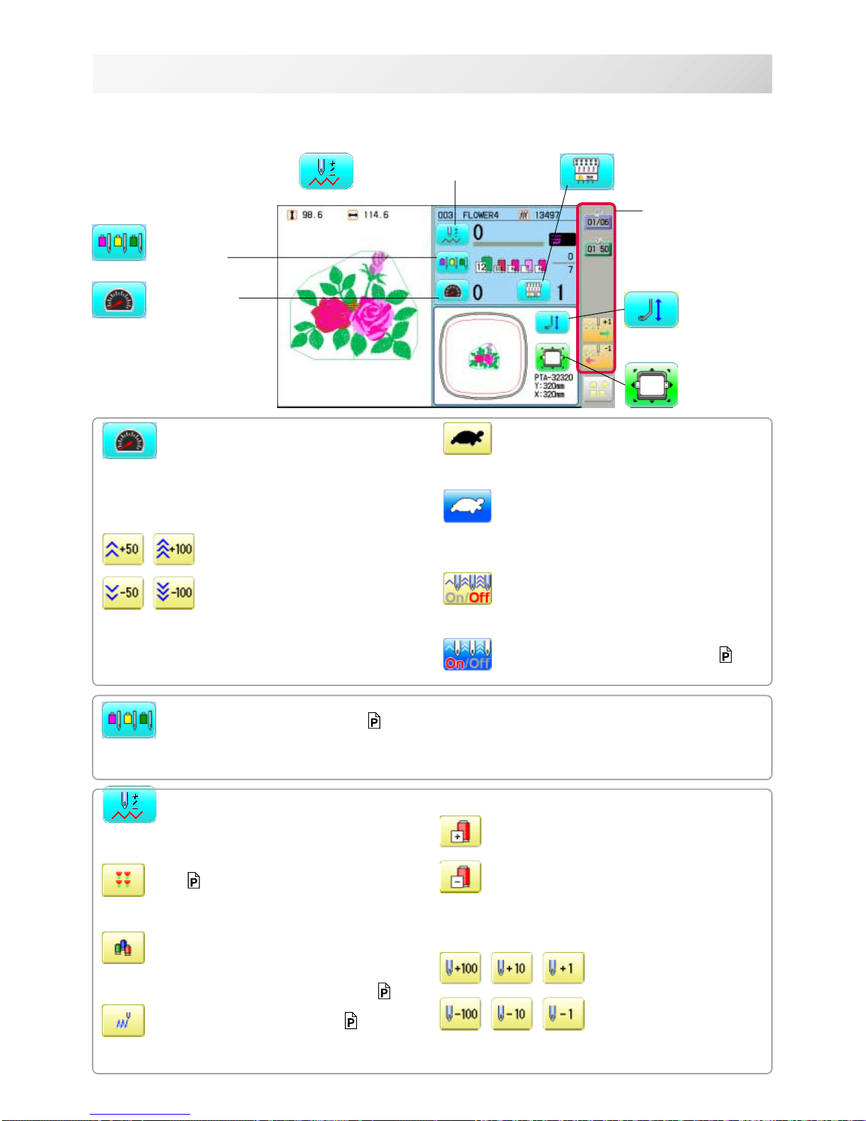
The each key menu will be shown.
Frame forward
This creates direct designations to the position and
data to the designated sewing position.
Piece 9-C
If "Repeat" is set, this allows the frame to move to
the beginning of any piece at will.
Change (Color position )
This moves the frame to the beginning of any Color
change number at will beginning of color. 9-6
Stitch (Number of stitches ) 9-7
This moves the frame to any stitch at will.
Frame forward
Needle bar
selection
Drive speed
Needle change
Frame move
i-Custom
(default display)
Pressure foot
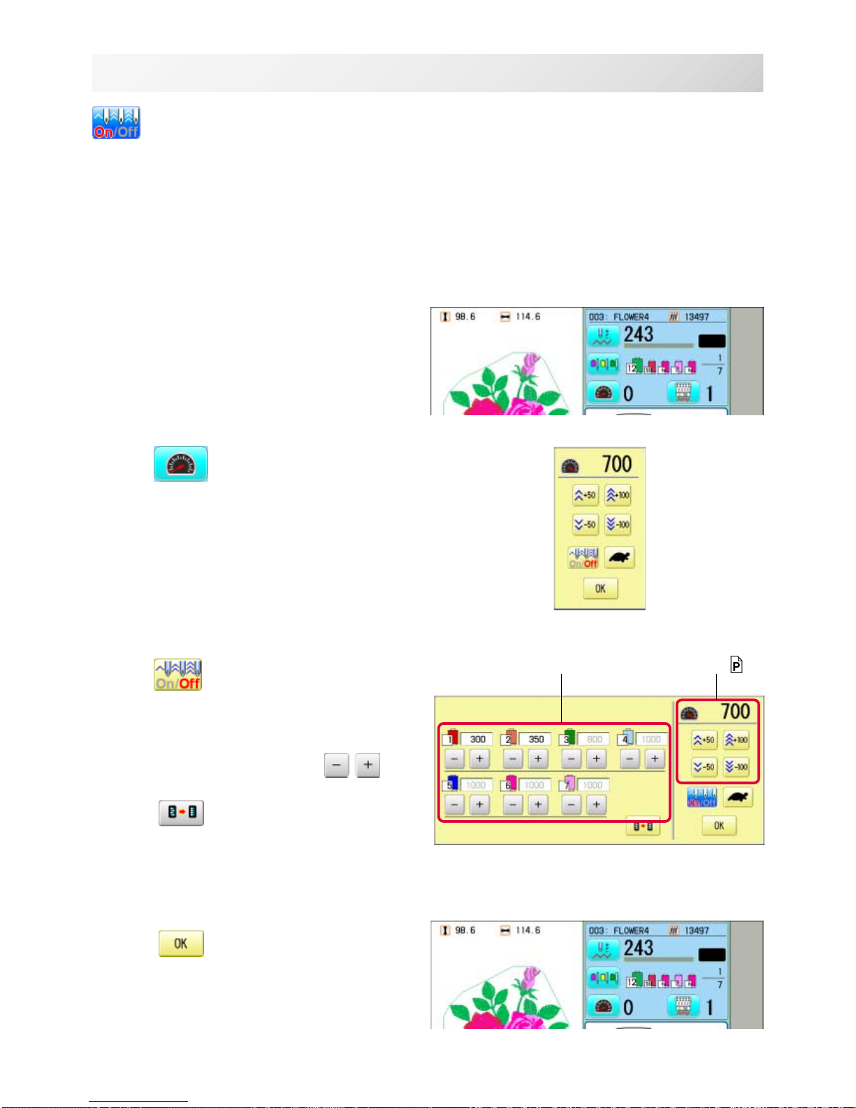
Drive speed
Control embroidery speed.
The speed can be controlled while embroidering.
Speed control
Press the + button to increase the machine sewing
speed and the - button to lower the machine speed.
is displayed on the LCD display.
Low speed operation (OFF state)
Press the button to turn "ON" state.
Low speed operation (ON state)
The drive speed will be reduced to "200 rpm".
Press the button to turn "OFF" state.
Speed setting by needle (OFF state)
Press the button to turn "ON" state.
Speed setting by needle (ON state) 3-7
Press the button to turn "OFF" state.
Needle bar selection 5-E
For each color change in a given pattern, the needle number loaded with the correct color thread is
assigned by the operator.
Color position forward
Move the frame to the beginning embroidery
position of the previous or later color position
number
Stitch number forward
Move the frame forward or backward by the stitch
number displayed in each button.

-SJ -193_5 O512
3-5
DRIVE MODE
Needle change
Change the needle bar directly to the indicated
needle number on the button.
Change
Move the sewing head to the adjacent needle in
the direction of the arrows.
Pointer
Turn on and off the laser pointer.
Laser pointer is located at right side of needle
no.1.(Needle no.0 position).
When laser pointer is turned on, moving head
moves to needle no.0 position and radiates.
Pressure foot
You can raise or lower the presser foot .
Jump (Off)
The machine can embroider.
Jump (On)
Machine becomes jump and the machine
doesn't
embroider.
-SJ -20
3_9c O512
3-6
DRIVE MODE
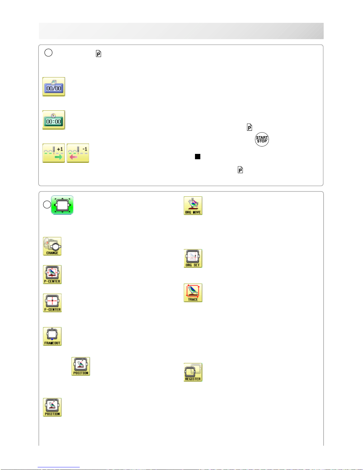
Original point return
This returns the frame to *pattern origin point.
After performing this action once, repeating this
again will cause the frame to return to the previous
position.
Origin registration
Register the current frame position as origin.
Trace
When pressed while at the beginning of design,
the embroidery frame moves following the outer
edge of the design. This allows you to compare
the design size and position against the frame
before sewing.
Indicate target design on LCD panel when nonshowing design.
If you press this key and hold, re-display your
Register
Register will restore the position of the frame to
the last point before a power failure even if the
point of origin or the pattern itself were changed.
6
Frame move
Selection the way of frame movement and
Move frame.
Frame change
Change the frame to be used.
Design centering
Move design to the center of frame.
Center
Moves the embroidery frame to the center automatically.
Frame out
Move frame to the front position which was set
before.
Press (Position) to return the frame to the
original position before frame out position.
It is convenience if hand work is required in the
middle of embroider process.
Position
When sewing is interrupted in the middle of a
design, this returns the frame to current sewing
position regardless of where frame may have
been moved with the arrow keys after interrupt.
target design.
5
i-Custom 22-1
The following display and key icons are set as default. You can place other frequently used icons freely on
the right side of Drive mode screen.
Calendar
Current year, month date is displayed.
Clock
Current time is displayed.
Stitch number forward
Move the frame forward or backward by the
one
When the key is pressed continuously, the "Key
lock" function is activated and the frame will move
continuously even the finger is released from the
key.
When the key is pressed much longer, the step of
"Stitch number forward" will be changed from one
stitch to 10 stitches. 5-2
When you stop it, press (Start/Stop button).
The "Key lock" and "Fast forward" function will
be activated after setting through ÅgMachine
SettingÅh menu. 15-2
-RA -23
3_9d O512
3-6a
DRIVE MODE
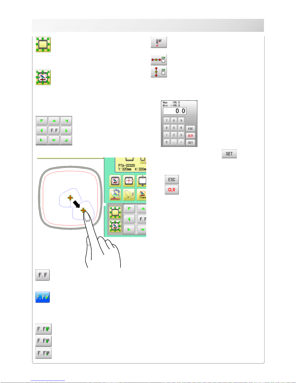
Fast move (OFF state)
Press the button to turn "ON" state.
Fast move (ON state)
Press this key one time to move the frame faster
toward the direction of the arrow.
Press the button to turn "OFF" state.
Fast move speed setting (High)
Fast move speed setting (Middle)
Fast move speed setting (Low)
The speed of "Fast move" can be adjusted.
Pointer (Option)
Turn on and off the laser pointer.
X Direction frame move
YDirection frame move
The frame can be moved with specified distance
along X axis or Y axis. (Unit: mm)
The function allows you to move the frame
precisely with a pitch of 0.1mm.
Select the number, and press .
The frame will move specified distance.
Changing is cancelled.
Numbers are deleted.
Quick move
First press this key and then the arrow key to
move the frame toward the edge of the embroidery area in the direction of the arrow.
Quick embroidery design data position
move
First press this key and then the arrow key to
move the frame where the design data can be
embroidered at
the edge in the direction of the arrow.
Frame move key
The frame moves toward direction of the arrow
mark.
You can move the
embroidery frame by
pressing desired
position on the
screen.
-SJ -20
3_9d NB01
3-7
DRIVE MODE
Speed setting by needle (ON state)
Embroidery speed can be set by needle.
If speed by needle exceeds the speed set at Drive speed setting, the value of speed turns gray
and speed by the needle is applied to the speed set at Drive speed setting.
You can be set up taking the following steps.
1. Press
.
2. Press
.
3. Change the setting on the needle number
you would like to change with
.
Press when returning the setting on all the
needle numbers to maximum.
4. Press .
The screen returns to Drive mode.
Speed setting by needle Drive speed setting 3-9
-D2 -25
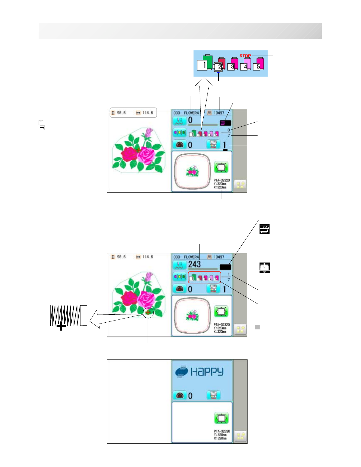
Memory # of selected pattern
Currently-selected
needle
Number of stitches sewn up to now
Name of selected pattern
Top
When beginning an embroidery
Machine stopped during embroidering
Display example
Status
Top
This indicates that the
machine is ready to start
sewing from the "top"
memory position of the
pattern.
Frame out
This indicates that a
frame out is occuring.
3_A NB01
3-8
DRIVE MODE
Pointer
Color change number
sewn up to now
Stitches of pattern
Needle number and color
*Color change number
Pointer indicates the
position of actual stitch
point.
If a needle number is not
assigned to a Color
change number, the
default color will be
assigned automatically.
Shift to left when color
change.
Size of pattern and distance
Heigh
t Width
Current *Color change
number
Mark for color
change stop
Mark for frame out
Selected frame
Display if the machine has no design
in memory
-SJ -21
Select a needle of the right type. See the following “SELECT THREADS”.
1
2
4
3
A
4_1 N518
4-1
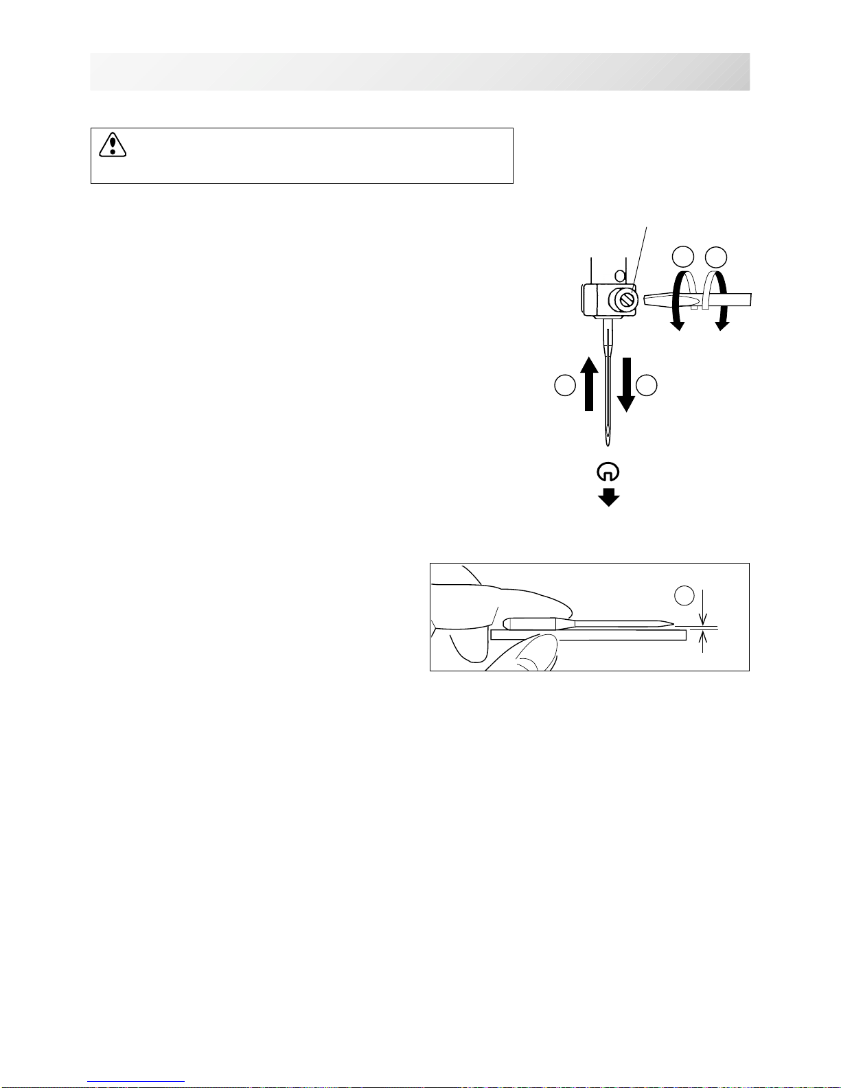
Needle clamp screw
INSERTING A NEEDLE
Front
CAUTION: To prevent accidents.
Turn off the power before removing the needle.
1. Loosen the needle clamp screw slightly with the screwdriver.
2. Remove the needle.
3. Insert a new needle into the needle clamp with push it up
as far as it will go keeping the slotted side of the needle in
front.
4. Tighten the needle clamp screw with the screwdriver.
A. Do not use a bent or blunt needle.
Place the needle on a flat surface and check
for straightness.
-CS -20
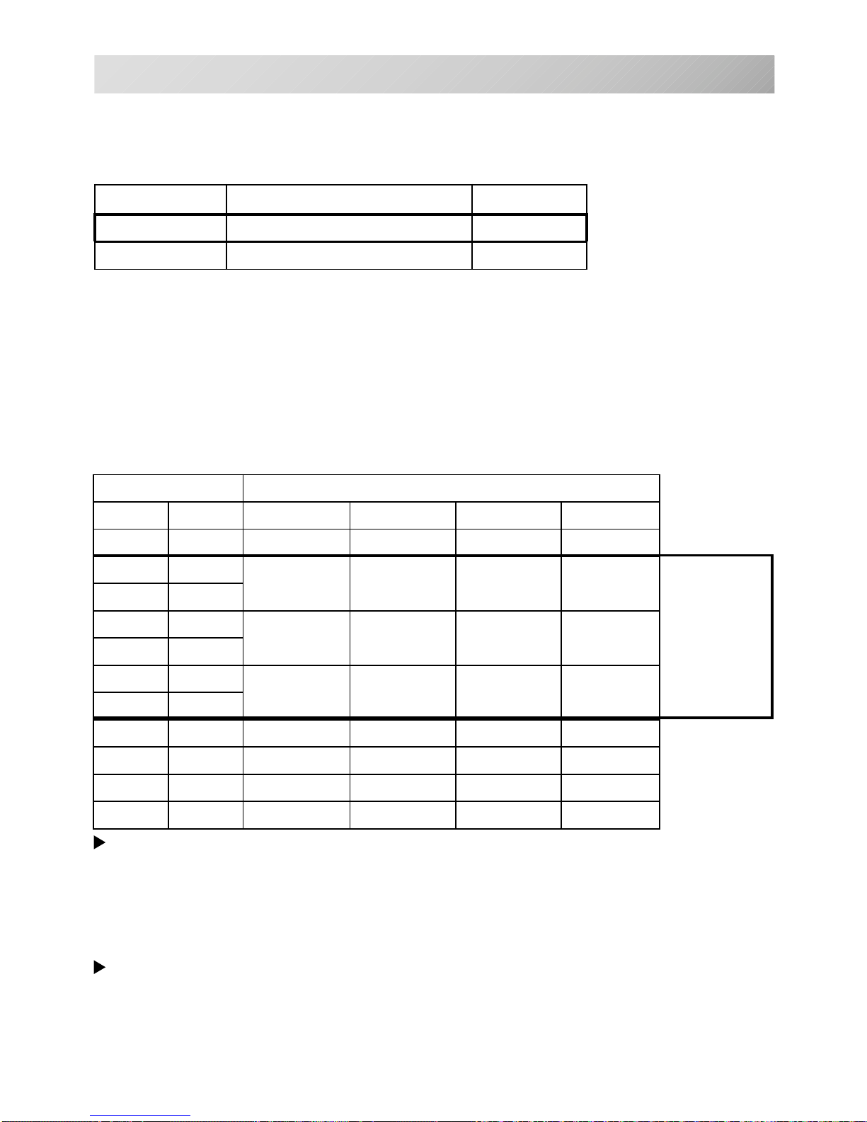
SELECT NEEDLES AND THREADS
About needle
Please select needles by type of material .
Normally, We supply a DB X K5 needle as in the machine accessory kit.
4_2 D607
4-2
Relation of needle and upper thread
Please select type of needle and upper thread by flowing list.
eziSdaerhtreppudnaeldeenfonoitaleR
nagrOnamreG#nottoCkliSretseyloPnoyaR
8#06#031~001061~041002~05107~05
956
08~07021~001051~031001~07
0107
1157
06~05001~08031~001031~001
2108
3158
04~6307~06001~08051~031
4109
5159
6100163~0306~0508~06061~051
71501
8101103~4205~0406~05032~081
Normal embroidery field
Normal use embroidery needle and upper thread.
Upper thread : Rayon 120 d/2 (120 denier)
Polyester 120 d/2 (120 denier)
Needle : #11 ( DB X K5 )
If the relationship of needle size and thread type is incorrect, it is possible to have any of the
following problems.
• Thread break
• Skip stitch (Upper thread does not catch bobbin thread)
• Other stitch quality problem
EPYTNOITACILPPA
eziSeldeeN
32K-BDtinkroF21~9
5KXBDyrediorbmelamronroF81~9
-CS -21
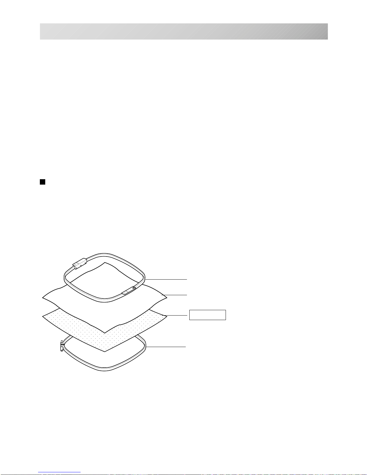
BACKING MATERIALS
Backing
Generally, Backing is used for hooped embroidery fabric. Knit fabrics particularly require the use
of embroidery backings.
Embroidery backings will allow the hoop to move the fabric more accurately, creating a more
beautiful embroidery.
Select backing type
Choose the thickness and number of sheets by the type of material and embroidery condition.
Generally, you should consider the following items.
•Embroidery stitch quality
•Contraction or compression of fabric caused by sewing, etc.
•Stiffness of fabric
In case, if you sew lace and leather, you may not need backing sheet.
Example of using a backing
4_3 D607
4-3
Embroidery frame (Inner frame)
Fabric
Backing sheet
Outer frame
-SJ -21
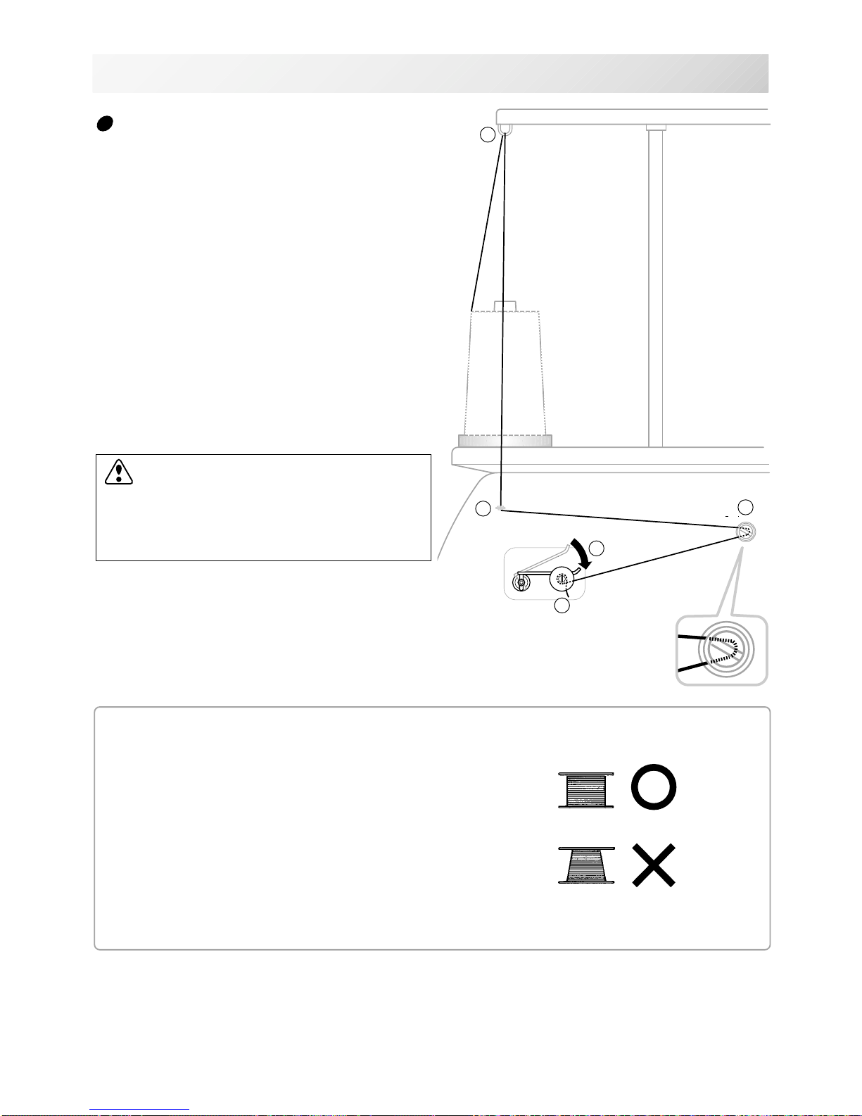
BOBBIN WINDING
Winding the bobbin
4_4 N518
4-4
Thread the bobbin winder as shown below:
1. Upper Thread guide
2. Thread guide
3. Winder thread guide
4. Bobbin (Place the bobbin on the bobbin winder
spindle.)
5. Press the limit lever as indicated by the arrow
to start the winder. The lever stops the winder
automatically after the winding is complete.
1
2
3
4
5
• Ensure thread winds evenly on bobbin as
shown.
Confirm that the bobbin is wound properly.
CAUTION: To prevent accidents.
When lever is pressed down, the bobbin
winder spindle and the bobbin start turning.
Keep fingers and body away until the bobbin
winder stops turning.
-CD -29
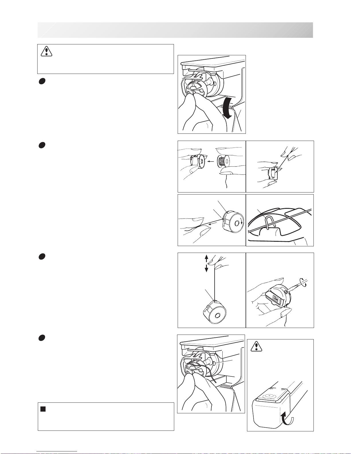
B
A
4_5 N525
4-5
A
B
B
C
B
A
A
BOBBIN WINDING
Removing the bobbin case
1. Open hook cover (A) to front.
2. Grasp bobbin case latch (B) and withdraw
bobbin case from hook taking care not to
damage the thread keeper.
Inserting the bobbin case
1. After threading bobbin in case, open bobbin
case latch (A), grasping it in fingers as
shown.
Slip bobbin and case on stud of rotary hook
body, and press in securely. Release bobbin case latch. Press the bobbin case in to
be sure it is fully seated.
2. Close hook cover.
Inserting the bobbin
1. Hold the bobbin case in left hand. Hold the
bobbin in your right hand with thread on top
leading from left to right.
2. Insert bobbin in case and draw thread up
into slot in case.
3. Draw thread under tension spring (A) and
wind into guide coil (B). The bobbin should
turn clockwise in the case when the thread
is pulled.
Adjusting bobbin thread tension
1. Hold bobbin thread and jerk upward approx.
an inch. Thread should unspool further
approx. the same amount.
2. The screw on the tension spring is for
adjusting bobbin tension. This adjustment
is very delicate. Please turn the screw only
a small amount. Only 1/8 of a turn
maximum.
CAUTION: To prevent accidents.
Please watch out for the point of the rotary
hook when you replace the bobbin.
Increase
Decrease
The attached bobbin case is available only
for this machine. Thread may be caught in
thread guide coil if other types are used.
CAUTION: To
prevent accidents.
Keep hook cover close
and fingers away while
the machine is running.
-SJ -19
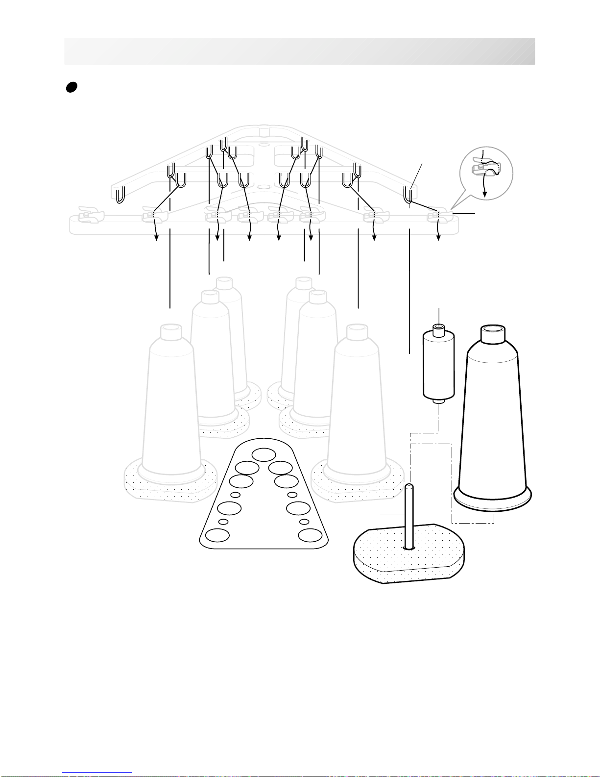
THREADING THE MACHINE
4_6 N401
4-6
How to thread upper thread
Pass upper threads in order according to the figure:
1. Thread stand
Set thread cone on the stand.
Small cones can also be used as shown.
2. Thread guide
Thread through the thread guide above each
thread cone.
3. Upper rectifier
Continued next page
1
2
3
45
6
7
1234567
1
2
3
45
6
7
2
4
5
745
1
2
3
4
6
7
5
36
Thread stand
Small cone
Thread guide
Upper rectifier
-SJ -23
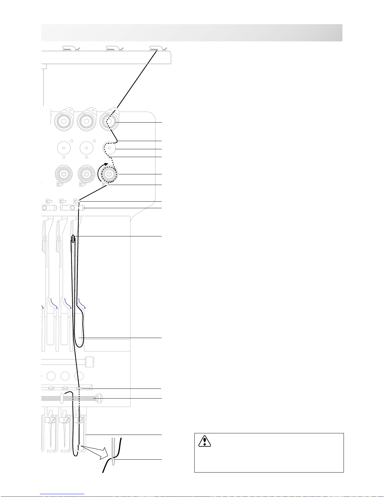
THREADING THE MA CHINE
4_7 N518
4-7
CAUTION: To prevent accidents.
Please be careful of the sharp point of the
needles when threading upper threads
through the needle.
4. Minor thread tension
5. Guide pin upper
6. Detecting roller
7. Guide pin lower
8. Thread tension
Wind upper threads one time around rotary
tension disc clock-wise.
9. Upper thread guide
10.Lower thread guide
11.Lower rectifier
12.Thread adjusting spring
13.Take-up lever
14.Thread guide plate lower
15.Needle
Thread from front side of needle.
Pull upper threads slowly and see that the detecting roller moves smoothly by pulling the thread
downward as much as possible.
16.Pressure foot
17.Thread holding spring
Push thread into spring.
4
6
7
8
9
10
11
13
12
17
14
16
15
5
-SA -12
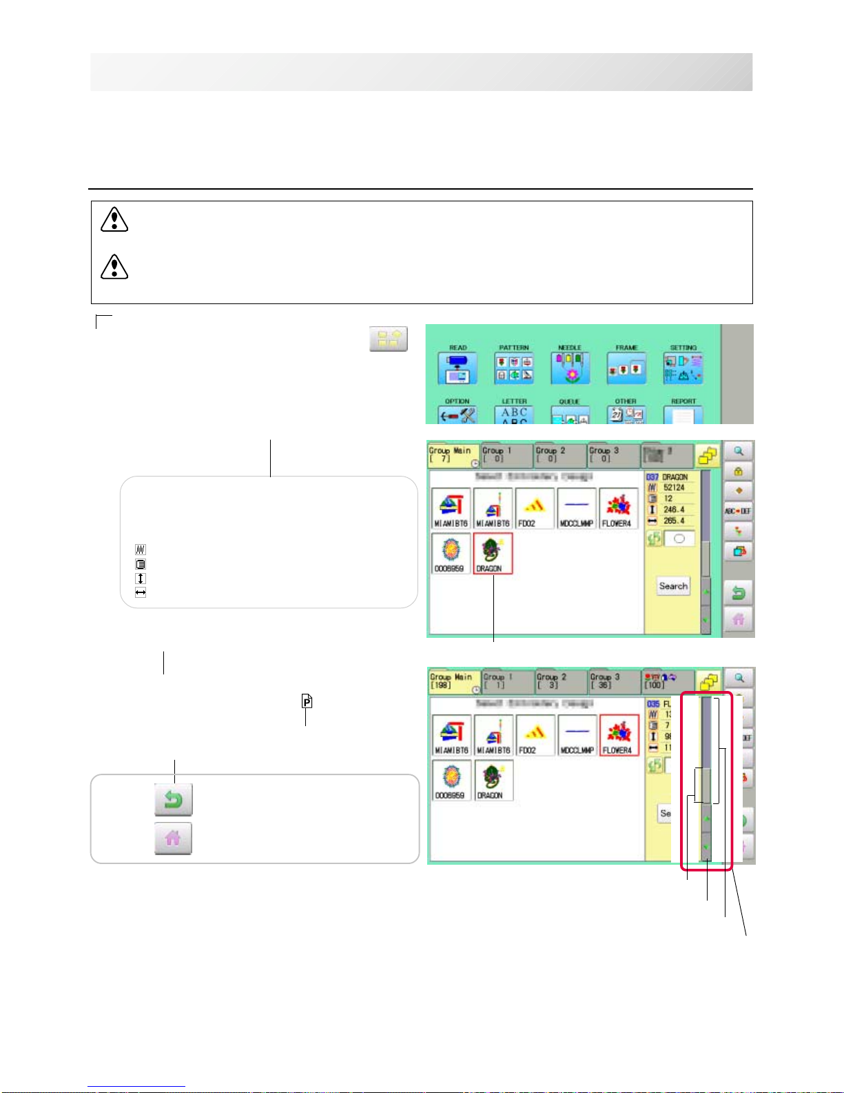
HOW TO READ THESE INSTRUCTIONS and SCROLLBAR
4-8
3_3 NB01
The instructions in this manual have been formatted as follows:
Written instructions will be provided on the left side of the page while graphics depicting the
necessary steps are provided on the right.
Graphics on the far right will show the display after performing the steps indicated.
This indicates an additional
explanation on an operation
elsewhere in the manual for
more detail.
AWords marked with a "*" are explained in
"EMBROIDERY TERMS" at the end of this
instruction manual.
CAUTION: To prevent accidents.
This will appear for items related to your safety.
CAUTION: To avoid problems.
This will appear for items related to potential problems.
Order of operation
Indicates supplementary
explanation regarding a
given operation or action.
1. When the machine is stopped, press .
2. Select "PATTERN".
The display indicates the current pattern.
The left side of display shows the number, name
and details for the current pattern.
Number of stitches
Number of Color change number
Height
Width
3. Select *pattern data.
This pattern will be selected.
3-3
Selected pattern data
Operation key
Press to return to Menu mode.
Press to return to Drive mode.
Scrollbar
Display area
Scroll area
Arrow key
Scrollbar
If the data are too much to fit into display screen, you can use scrollbar.
Display area : It shows the area which is displayed.
Arrow key : You can scroll the display area to arrow marked direction.
Scroll area : It shows the whole area of the data.
You can push arbitrary point of Scroll area to display the desired location.
 Loading...