

Happijack FT-DR8 Installation Manuals
Frame Mount
Camper Tiedown System
Models: FT-DR8
FRONT ANCHOR INSTALLATION
"L" Shaped Frame Brace
Guide Plate
Stabilizer Bar
LOADING, UNLOADING & LEVELING THE CAMPER
When loading and unloading, the height at which the camper is set above the bed is critical to the proper
operation of the rear centering guide locks.
ALWAYS: Keep the camper bottom within 2" of the truck bed. While it is important to keep the camper close
to the truck, serious damage and injury can result if the truck "hooks" the camper as you pull from beneath it.
MOVE SLOWLY!!! Be Careful.
NEVER: Allow the camper to come above the rear centering guide locks! If the camper were lowered onto
the top of the centering guide lock, severe damage could occur to truck, camper, or both!
NEVER: Rely on the centering guide locks to align the camper as you load. While they will move the camper
SLIGHTLY side to side, their purpose is to lock the camper in place, on center in the truck once loaded.
Attempting to load when truck to camper alignment is poor can also cause serious damage to truck bed,
wheel wells, tail lights, etc.
ALWAYS: Remember to remove the turnbuckles prior to raising camper to unload.
NEVER: Attempt to level the camper on the truck with the turnbuckles installed!
ALWAYS: Remove the turnbuckles before leveling the camper. Your jacks were not
designed to lift both the truck and camper. Damage to the truck, tiedowns or camper is also likely to occur if
the turnbuckles are not removed when leveling.
NEVER: Lift the camper completely off the truck to level unless the truck is being moved
from beneath the camper and the camper is being lowered close to the ground. The camper is not stable at
that height and unsafe for occupancy unless resting on the truck.
ALWAYS: Lower the camper as close to the ground as possible when not on the truck.
The closer to the ground, the more stable the camper becomes.
NEVER: Allow the front of the camper to become lower than the back when loading or unloading. Doing so
shifts a tremendous amount of weight over the front jacks which could cause a dangerously overloaded
situation. Whenever the camper is not on the truck, it is a good idea to keep the front 4" higher than the back.
Except when the camper is lowered close to the ground and leveled for occupancy.
NEVER: Leave the camper up in the air on extended jacks. Lower the camper as low as possible when not
on the truck.
Guide Plate
G
u
ide Plate
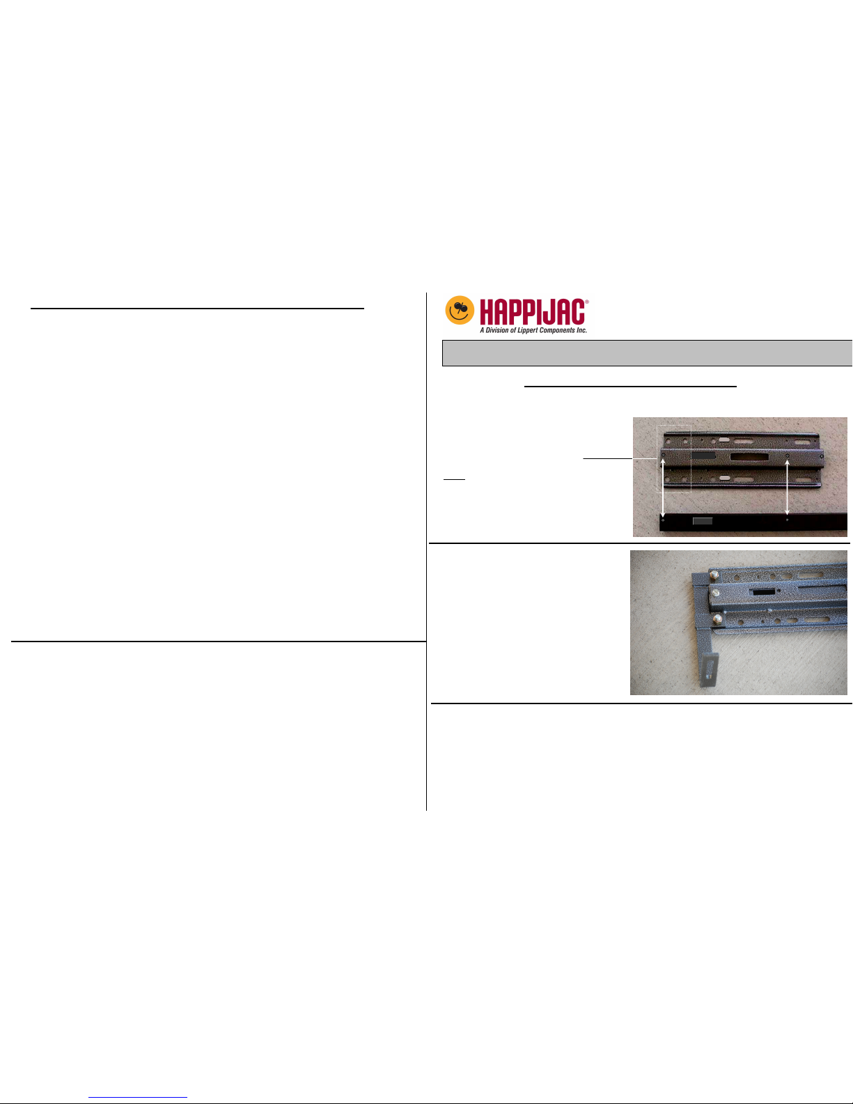
STEP 1 – Place the guide plates over the stabilizer bar and attach
both using #10 x ¾” sheet metal
screws provided in Kit A.
The arrows show the location of
these sheet metal screws.
Note: The 4 large round holes
in guide plate must be to the
outer ends of the assembly at both
ends.
STEP 2 – Attach frame braces to guide
plates using 4 of the 3/8 fine thread
bolts and corresponding nuts, secure
the frame braces to each end of the
guide plates as shown.
Note: Tighten the nuts just to finger tight
They will be removed and discarded later.
STEP 3 – [Hardware Kit B]
In this step, refer to the illustrations on the following page.
Center the assembly against front wall of truck bed. Select the screw location (A or B) where the
silver/gray guide plate fits tightest against the front wall. Drill a 3/32” pilot hole for the sheet metal
screw at best locations. Note: These screws are used to hold the assembly in place while drilling
the mounting holes for the anchor plates. Generally only one screw per side is needed.
It is a good idea to put a piece of wood between the bed and cab to prevent drill bit
from striking the cab.
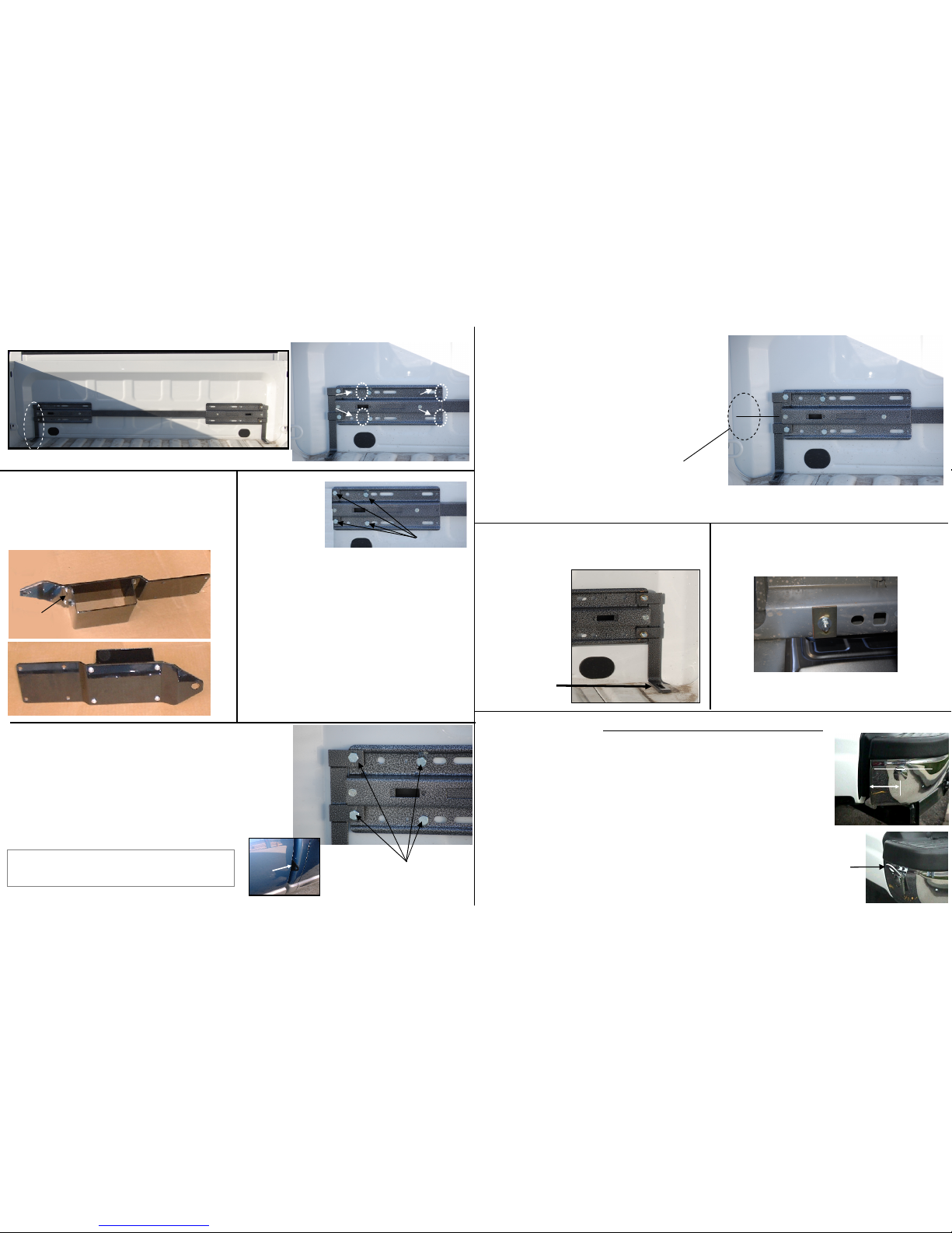
STEP 8 – [Hardware Kit D]
Drill 3/8” dia. Hole through frame brace foot ,
bed, and frame/bed cross member 3 inches
back from bed
front wall.
Make sure drill
is as close to
vertical as
possible in
all directions.
STEP 7 – [Hardware Kit J] Using the #10
self drilling & self tapping screws, install 2 screws
through bed front wall into the black anchor plate at
the locations shown.
NOTE: A small pilot hole may be drilled but is normally
not necessary as this particular screw will drill it's own
pilot. Use a punch to start either the screw or pilot bit to
avoid
drift.
Set 1-3/4" each side of a center line drawn
from the guide plate & approx. 1"
back from bend in bed front wall.
.
.
.
.
Mounting Holes
A B
A BA B
A B
#10 Sheet Metal Screw
(4 Places)
F
r
o
n
t
A
n
c
h
o
r
P
l
a
t
e
B
a
c
k
i
n
g
P
l
a
t
e
Short
Flange
STEP 3 - Continued (Illustrations)
STEP 6 – [Hardware Kit B] Install Front Anchors.
This is most easily accomplished if one person pushes
the bracket up between the bed and cab from beneath
the truck, while another starts the bolts.
Remove board from between bed & cab and slide black front
anchor plate assembly into place. Reset the frame braces
on each end of the assembly. Start but do not tighten
all 4 bolts through guide plate and frame braces.
into threaded holes in black anchor plate.
Hint: The bolts will start easier if prior to installation
on truck, you run the bolts or a 3/8-24 tap through the
threaded holes in the anchor plate to clear out paint.
Cab
Anchor
Plate
x
STEP 9 – Insert 5” carriage bolt through hole
and secure from beneath truck with reinforcing
plate, flat washer, lock washer & hex nut.
THIS COMPLETES THE FRONT ANCHOR
INSTALLATION.
Bed cross
member
Grounding strap
REAR ANCHOR INSTALLATION
NOTE: Rear anchors are installed in the end of the bumper. There is no
precise mounting location since a variety of bumpers may be
installed. The general guidelines are as follows:
1. Mounting location should be as flat & vertical as possible.
2. Be sure no moldings or bumper caps interfere with removable coupler.
3. Check back side of selected mounting location to ensure adequate
access for tightening nut.
4. Choose a location as far back as possible from the front edge of bumper
while giving consideration to the other criteria listed above and center
punch and drill a 1/8” pilot hole, then enlarge to 1/2”.
Install Anchor Bolt with 2” fender washer, lock washer & nut.
Flat edges of Anchor Bolt must be horizontal.
Remove
coupler
when not
in use to
prevent loss.
Flats Horizontal
Place well back
From front edge
Of bumper
STEP 4 – Front Anchor Assembly
Attach backing bracket to front anchor plate
using the1/4" sheet metal screws provided in
hardware Kit J. (Short flange toward tip)
Remove the frame braces from the ends of the assembly and using the
sheet metal screws provided, secure the assembly to the front wall of the
Truck bed.
Remove frame braces
STEP 5 – Drill
four 7/16" holes
through guide
plate and bed
front wall using
the four large
round holes
as a drill guide.
These holes
align with
the threaded
holes in
the black anchor
plate.
It is a good idea to put a piece of wood
between the bed and cab to prevent drill
bit from striking the cab.
7/16”
3/8” fine thread bolts through
bed front wall into black
anchor plate
.
.
 Loading...