

Happ Vision Pro MTG-1901CN, 49-1329-VP2, Vision Pro MTG-1301CN, 49-1345-VP2 Service And Operation Manual
SERVICE AND OPERATION MANUAL
MTG-XX01 SERIES (13”,19”) CGA
OPEN FRAME COLOR MONITORS
19”: 49 - 1329 - VP2
13”: 49 - 1345 - VP2
MTG-XXO1 Publication A, Issue 1
Information in this publication cur rent as of June, 2003.
Information subject to change as display technology advances.
2
This monitor has been designed and manufactured to deliver high performance video. For continued peak
performance use and safe operation, it is recommended to use only high quality Happ Controls replacement parts
or their exact specified equivalent when servicing.
SAFETY PRECAUTIONS AND WARNI NGS
Service Warning
The display contains HIGH VOLTAGE capable of
delivering LETHAL levels of energy. Service should
only be attempted by trained personnel familiar with
the potential dangers inherent with high voltage
equipment.
Safety Related Component Warning
Certain components used in Happ Controls color
monitors are critical for safe operation of the display.
These part numbers are marked by () on the
schematic diagram. It is essential that these safety
critical components be replaced only with exact
manufacturer specified components to prevent the
possibility of excessive X-radiation emission, electrical
shock, fire or premature component failure. Modifying
the original design without written approval from Happ
Controls is expressly forbidden, will void the original
parts and labor warranty, and may result in creating a
hazardous situation.
X-Radiation Warning
COMPONENTS WHICH MAY AFFECT POTENTIAL
EXCESS EMMISSION OF X-RADIATION IN THE
HORIZONTAL DEFLECTION AND HIGH VOLTAGE
CIRCUITS(INCLUDING THE PICTURE TUBE) ARE
INDICATED ON THE SCHEMATIC DIAGRAM BY
A(★).
USE ONLY TYPE AND RATING OF REPLACEMENT
COMPONENT AS SHOWN IN THE PARTS LIST.
1. The only potential source of X-radiation emission
is the picture tube. When the high voltage and
horizontal deflection circuits are operating correc tly
there is no possibility of excess X- radiation
emission. NEVER attempt to modify these circuits.
2. Periodically check the high voltage with a reliably
calibrated meter for values no tin excess of
manufacture recommendations.
See High Voltage
Shut-down Circuit, page 4 for further details.
CRT Warning
All picture tubes used in Happ Controls monitors are
quipped with an integral implosion protection system.
The picture tube is, however, a highly evacuated
component which outside surfaces are subject to
strong external forces. Care must be exercised so as
not to bump or scratch the tube during installation or
servicing as this may cause the tube to implode,
resulting in possible personal injury and property
damage. Shatter-proof goggles must be worn by
individuals while handling the CRT or installing the
display in the cabinet. Do not handle the CRT by neck.
1. Always ensure the high voltage at the anode cap
is fully discharged prior to handling or service.
2. Replace picture tube only with same type and
number.
Product Safety and Service Guidelines
1. Service should be performed only after reading
all of the warnings and precautions in the manual
and as labeled on the CRT and chassis.
2. Where a short circuit has occurred, replace all
components that indicate evidence of overheating.
Also check for evidence of overheating or poor
connection on all plastic connectors.
3. Inspect wiring for frayed leads and damaged
insulation. When service is required, observe
original lead dress, assume lead dress is followed
as from the factory, especially in the high voltage
circuitry area.
4.
Do not expose this display to rain or place in areas
where the potential for exposure tomoisture is high.
Additionally, do not mount the removed
VR PCB if
so equipped outside the cabinet or in areas where
there is a possibility of exposure to moisture.
5. All protective devices must be reinstalled per
original design.
3
1. Power Supply
This color monitor shall maintain the spec
ified
performance in the range described below.
Frequency : 47Hz ~ 63Hz
Vol
tage : 90VAC-264VAC
Consumption : Less t
han 70Watts
2. Input Signal
The referenced video controller used for adjustment
and test will guarantee
the performance described
below.
Video signals
Red, Green, Blue analog input
150Ωtermination to ground
Level : 0 to 2.4Vp-p
Polarity : Positive
Sync signals
Separate H/V sync input
10k termination to ground
Level : TTL level
Polarity : Positive or Negative
3. HorizontalDeflection
Scanning Frequency : Nominal (15-17.5kHz)
Retrace period : 〈 11.5us
4. Vertical Deflection
Scanning Frequency : Nominal (50-65Hz)
Retrace period : 〈 900us
5. Linearity
±5%
6. Picture Size Regulation
Static Regulation 2%
Dynamic Regulation 1.5%
7. Geometric Distortion
It is acceptable that pincushion, trapezoid, paralle-
logram, barrel distortion, out of orthogonality and
various waves can
appear all together. If the data
area parameter remains within the limits of 2%.
8. Degaussing
This color monitor
shall employ an automatic
degaussing circuit, The degaussing sequence
shall be self activated at the time of switch-on.
After a degaussing cycle, the demagnetizing circuit
shall recover.
9. High Voltage
This color monitor shall employ an X-radiation
shut-down protection with internal circulitry.
13" : 26KV
19" : 27KV
10. Environmental Conditions
Temperature : 10 ~ 55℃ (Operating)
Humidity : 10 ~ 90%, no condensation
1. Apply line AC,90V-264V, in your locality to the
monitor through W801.
2. Apply signal source to the monitor through W301.
3. Set up user adjustable controls.
All controls are preset at the factory for optimum
performance. If adjustment is necessary to suit
program material, most adjustments can be made
using o nly the controls on the remove VR PCB.
Other controls in the monitor should be adjusted
only if those controls have been tampered with or if
major repairs were necessary on the monitor.
PERFORMANCE AND OPERATING DATA
OPERAT ING INSTRUTIONS
4
1. Remote VR PCB
Contrast, VR720
Brightness, VR721
H-Pos
ition, VR722
H-Size, VR723
V-Size, VR724
V-Position, VR725
2. Main PCB
Horizontal OSC, VR301
V-HOLD, VR303
V-LIN, VR302
3. Flyback Transformer
Focus Adjustment
Screen Ad justment
4. Neck PCB
Red Cut-off, VR552
Red Gain, VR551
Green Cut-of
f, VR555
Green Gain, VR553
Blue Cut-off, VR554
Blue Gain, VR556
These controls in main, neck PCB and flyback transformer have been preset and sealed at the factory
and should not require further attention.
The chassis of this color monitor has been
designed to emit a minimum of soft X-radiation,
in accordance with US DHHS rules 21 CFR,
subchapter J, applicable at date of manufacture
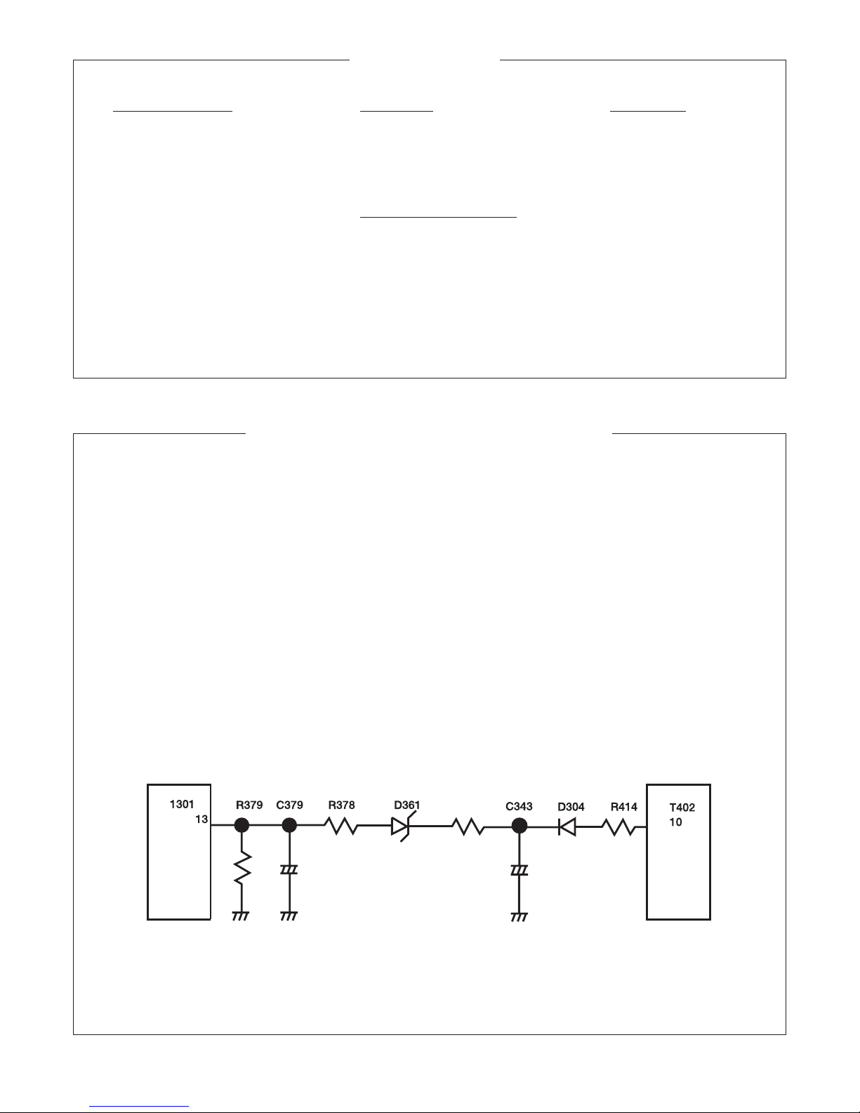
A high voltage shut-down circuit, as shown
below, guarantees hor izontal oscillation shut-
down.
A flyback pulse is generated at pin 10 of flyback
transformer. This pulse is fed through a
resistive divider network to pin 13 of I301.
The voltage appearing on pin 13 is compared
with a precise internal voltage in the IC should
the EHT exceed 28KV the change in voltage on
pin 13 actuates a circuit which inhibits the
oscilator and consequently the EHT circuit.
The c ircuit continues to inhibit the oscillator
until the fault condition is corrected, and even
then the monitor has to be switched off and on
cillator cable is re-activated.
HIGH VOLTAGE SHUT-DOWN CIRCUIT
CONTROLS
 Loading...