

Page 1

IDENTIFICATION
About this documentation:
This documentation was originally produced in Dutch by:
Wagenbouw HAPERT
Version name : User documentation/CE/warranty conditions
Fifth edition : January 2019
© Copyright : Wagenbouw HAPERT BV, Hapert, 1998
No part of this documentation may be reproduced in any form whatsoever without the
permission of Wagenbouw HAPERT, except for those chapters that are intended to be
reproduced for use with this documentation, such as summarised instructions and
markings placed on trailers.
About the trailer:
This user documentation is intended for all HAPERT trailers.
For further information, see the type plate on the trailer.
About the manufacturer:
The trailer was manufactured by:
Wagenbouw HAPERT BV (in short: HAPERT)
Handelsweg 13
5527 AL Hapert
The Netherlands
Tel: +31 (0) 497 38 68 68
Fax: +31 (0) 497 38 68 82
Internet: www.hapert.com
E-mail: info@hapert.com
Page 2

CONTENTS:
IDENTIFICATION ................................................................................................... 1
FOREWORD ......................................................................................................... 5
USING THIS DOCUMENTATION ............................................................................... 6
TEXT CONVENTIONS ............................................................................................. 7
WARRANTY AND LIABILITY .................................................................................... 8
1. INTRODUCTION ............................................................................................ 10
1.1 Purpose and function of the trailer…………………………………….10
1.2 Models and accessories………………………………………………..10
2. SAFETY ...................................................................................................... 11
2.1 Introduction………………………………………………………………11
2.2 Safety regulations……………………………………………………….12
2.3 Unauthorised use………………………………………………………..12
2.4 Users……………………………………………………………………...13
2.5 Work area………………………………………………………………..13
2.6 Warnings on the trailer…………………………………………………13
2.7 Substances that are hazardous to humans and the environment…13
2.4.1 Operators ................................................................................ 13
2.4.2 Service personnel ................................................................... 13
2.7.1 General information ................................................................ 13
2.7.2 Storage ................................................................................... 14
2.7.3 Protection of the environment ................................................. 14
2.7.4 Disposal of the trailer .............................................................. 14
3. OPERATING INSTRUCTIONS .......................................................................... 15
3.1 Construction and operating devices…………………………………..15
3.1.1 Remote control system/Hapert remote control (optional) ........ 18
3.1.2 Using the remote control system ............................................. 18
3.1.3 Car2trailer automatic recharging system (optional) ................. 21
3.2 Using the trailer………………………………………………………….22
3.2.1 Connecting and disconnecting the trailer ................................ 22
3.2.2 Loading the trailer ................................................................... 22
3.2.3 Before pulling away ................................................................. 26
3.2.4 Tipping the trailer .................................................................... 27
3.3 Maintenance……………………………………………………………..29
3.4 Cleaning………………………………………………………………….31
4. OTHER MAINTENANCE WORK ........................................................................ 32
4.1 Repair and maintenance……………………………………………….32
4.1.1 Maintenance instructions ........................................................ 32
4.1.2 Repairing/replacing parts ........................................................ 32
Wagenbouw HAPERT 2
Page 3

5. SPECIFICATIONS ......................................................................................... 33
5.1 Trailer and weights………………………………………………………33
5.1.1 Wheels and tyres .................................................................... 33
5.1.1.1 Mounting brake system, axles and drawbar ............................ 33
5.1.2 Electrical system ..................................................................... 34
5.2 Tipping system…………………………………………………………..35
5.2.1 Tipping range .......................................................................... 35
5.2.2 Hydraulic pump ....................................................................... 35
5.3 Physical conditions of use………………………………………………35
5.4 Applicable directives and standards…………………………………...36
6. MARKINGS ON THE TRAILER ......................................................................... 37
6.1 Type/construction plate…………………………………………………37
6.2 Warnings………………………………………………………………….39
6.3 Vehicle details……………………………………………………………40
7. SERVICES ................................................................................................... 41
EU DECLARATION OF CONFORMITY .................................................................... 45
Wagenbouw HAPERT 3
Page 4

Wagenbouw HAPERT 4
Page 5

FOREWORD
This user documentation describes how to use a trailer delivered by HAPERT and how
to perform periodic maintenance. It is applicable to all HAPERT trailers.
It does not include details of work carried out on the trailer by the personnel of HAPERT
or an official HAPERT dealer.
This documentation should be considered an integral part of the trailer!
You should, therefore, store it in a safe place. It contains information that will be
useful or necessary in the future, for example for repairs and maintenance. This
documentation is included as part of the delivery of the trailer.
Besides the provisions stated in this documentation, statutory regulations for the use of
trailers, for example, number plate registration, maximum driving speed, etc. must also
be observed. The statutory regulations may differ per country and may change over
time. Make sure you observe the latest regulations!
Wagenbouw HAPERT 5
Page 6

USING THIS DOCUMENTATION
This documentation describes various trailer models. The descriptions of parts only
apply to the respective types or models on which they are actually fitted.
The instructions in this documentation are categorised according to the type of user.
Chapter 2 contains details of the requirements that different users have to meet.
The following definitions are used in this documentation:
User: The collective name for anyone who works with or on the trailer.
Operator: The daily user of the trailer.
Chapter: Introduction, Safety and Operating Instructions.
Service personnel: People with the training, experience and tools required to carry out
the described work.
Chapter: All
Safety officer: The person who is responsible for safety in the company that
owns the trailer. If nobody is appointed as such, it will be the
employer.
Chapter: Safety and Specifications
Work that is not included in this documentation must be carried out by the personnel of
or in consultation with HAPERT or the official HAPERT dealer.
The figures included in the text of this documentation are purely illustrative.
They are only intended to clarify the respective text sections, for example, to indicate
the location and function of operating mechanisms or components. The actual design
and dimensions may differ.
Wagenbouw HAPERT 6
Page 7
TEXT CONVENTIONS
Except for the text in the “Safety” chapter, text segments that are important for personal
health and safety are printed in bold.
The following warnings may be placed on the trailer:
Attention!
This pictogram warns of possible damage to the load
or the trailer.
Warning!
This pictogram is a warning for the risk of personal injury.
Wagenbouw HAPERT 7
Page 8

WARRANTY AND LIABILITY
WARRANTY
Unless agreed otherwise in writing, the manufacturer issues a warranty to the first user
for a period of 24 months after delivery.
The warranty conditions given below are applicable.
Warranty conditions:
The warranty exclusively applies to faults that occur under normal use of the trailer
and that occur due to defective construction, or due to the use of poor materials or
poor workmanship on the part of the manufacturer.
Any defects or imperfections of the delivered goods must be reported to an official
HAPERT dealer in writing as soon as possible, but no later than eight days after
they have been discovered or could have been discovered.
In order to enable the official HAPERT dealer and the manufacturer to respond
adequately, the report must contain a description of the defect that is as detailed
as possible.
In the event that a defect is reported later, the owner/user will no longer be entitled
to repair, replacement or compensation, unless a longer period ensues from the
nature of the problem or the circumstances of the case.
The warranty comprises of the replacement or repair of the faulty product or parts
free of charge by the manufacturer or the official HAPERT dealer.
The warranty conditions of the respective third parties shall apply to any built-in
components supplied by them. The length of the warranty period may differ from
the period specified above.
No claim can be made under the warranty if:
The warranty certificate is not registered via WWW.HAPERT.COM/REGISTER.
The fault is the result of normal wear, improper use, improper treatment, use of
other consumer items than specified or improper or incorrect maintenance.
The fault occurs after changes or repairs made by the buyer/user or by third
parties on behalf of the buyer/user and if it concerns a fault to the trailer's
support wheel.
The owner/user fails to fulfil all of its obligations towards the manufacturer or the
official HAPERT dealer arising from any agreement whatsoever.
The condition of the trailer on handover cannot be proved (by means of a
handover inspection by the dealer).
It cannot be proved that the trailer has undergone the periodic services (after 6
months, after 1 year, etc.).
Wagenbouw HAPERT 8
Page 9

Liability:
The manufacturer cannot be held liable for unsafe situations, accidents or damage
that are caused by ignoring warnings or regulations placed on the trailer or included in
this documentation, such as:
Incompetent or incorrect use, or poor maintenance.
Using the trailer for purposes or under conditions other than those given in the
documentation.
Using components other than those prescribed in this documentation.
Performing repairs without permission from the manufacturer.
Making changes to the trailer, such as:
Changes to the control system.
Welding, mechanical treatment, etc.
Adding items to the trailer or its control system.
If the buyer of the trailer has not fulfilled all his obligations (financial or otherwise)
to the manufacturer.
For consequential damage caused by defects or the malfunctioning of the trailer
(for example damage to products (to be processed), interruption of work in
progress, delays, etc.).
Wagenbouw HAPERT 9
Page 10

1. INTRODUCTION
1.1 PURPOSE AND FUNCTION OF THE TRAILER
The trailer is intended to be used to transport both bulk goods and individual items. The
trailer consists of a chassis with a single axle, tandem axle or tridem axle on which a
cargo bed is fitted. For types COBALT HB and the INDIGO HT and LT the cargo bed
can be tipped backwards by means of a hydraulic pump and cylinder. For type
COBALT HM and COBALT+, the cargo bed can be tipped to the left, right or
backwards, as desired by the user, by means of a hydraulic pump and cylinder.
1.2 MODELS AND ACCESSORIES
The (technical) specifications of all the HAPERT models and types are available in the
Media section of WWW.HAPERT.COM.
Wagenbouw HAPERT 10
Page 11

2. SAFETY
2.1 INTRODUCTION
The trailer has been designed in such a way so that it is safe to use and maintain. This
applies to the uses, circumstances and guidelines described in this documentation.
Everybody who works with or on the trailer must, therefore, read this documentation
and follow the instructions it contains.
In the case of professional use, it is the employer’s responsibility to ensure that the user
is familiar with the instructions and that they are observed.
Additional safety measures may apply in the company or country in which the trailer is
used. These measures mainly relate to the working conditions. This documentation
does not describe how these measures must be complied with. It does, however,
contain all the information you will need about the trailer. If you have any doubts, ask a
relevant government official or your safety officer.
In this documentation, a distinction is made between normal use (see chapter 3:
Operating Instructions) and other work (see chapter 4) carried out on the trailer. The
reason for this is that service personnel have to meet different requirements than the
operator, particularly with regard to safety.
Simple maintenance work described in the operating instructions can be carried out by
the operators.
Work that is not described in the operating instructions may only be carried out by
people who are qualified to do so. The accessories that are supplied with the trailer to
restrict access to specific sections or functions (such as the key to the main switch) may
not be stored on or near the trailer. These accessories may only be entrusted to people
with the required qualifications.
Wagenbouw HAPERT 11
Page 12

2.2 SAFETY REGULATIONS
Ensure unauthorised people, such as children, cannot operate the tipping
system. The key must be removed from the main switch when the trailer is left
unsupervised.
People may only use the trailer if they have read and understood the operating
instructions.
The tipping system may only be operated when the trailer is stationary, the brake
has been applied and the trailer is connected to a towing vehicle.
Do not climb on the trailer when the tipping system is being used.
Do not climb on the trailer if it is not connected to a vehicle.
When tipping the load off the trailer, make sure nobody is in the area where the
load is to be tipped.
Safety devices may not be removed or put out of operation.
Keep the workplace neat and tidy, and free of obstacles.
Make sure the surroundings are adequately illuminated.
Be aware of the risk of becoming trapped between the cargo bed and the frame
or the front, side and rear flaps.
A trailer must be on a stable surface (not to sink into gravel or sand) during
tipping. Trailer may fall.
Using the tipping system on an incline is dangerous. Trailer may fall.
When using tipping system always use the mounted supports. (For instructions,
see Section 3.2.2)
Do not exceed the maximum permitted load (see name/type plate).
Do not exceed the maximum permitted ball thrust (see name/type plate).
Do not exceed the maximum load of the tie rings
Only use the remote control after reading the operating instructions (see 3.1.2).
2.3 UNAUTHORISED USE
The trailer is especially not suitable for:
Transporting people or animals.
Using the tipping system to unload individual items.
Lifting people or goods.
Wagenbouw HAPERT 12
Page 13

2.4 USERS
2.4.1 OPERATORS
The trailer may be used by any adult who is familiar with and observes the instructions
in the “Safety” and “Operating Instructions” chapters. Special training is not required.
However, a relevant driving licence is required to drive a vehicle while towing a trailer.
2.4.2 SERVICE PERSONNEL
Special knowledge/experience and/or training is required. For the driving section:
knowledge and experience with regard to the maintenance of motorised vehicles. For
the hydraulic section: knowledge and experience with regard to the maintenance of
hydraulic systems.
2.5 WORK AREA
A work area of 100 cm around the trailer must be kept clear in order for the tipping
system to be operated.
2.6 WARNINGS ON THE TRAILER
The warning signs placed on the trailer must be clearly legible. If necessary, replace
them or have somebody else do this for you.
The text of the warning signs placed on the trailer are listed in the “Markings on the
trailer” chapter. The respective hazards are described in further detail in the operating
and maintenance instructions.
2.7 SUBSTANCES THAT ARE HAZARDOUS TO HUMANS AND THE ENVIRONMENT
2.7.1 GENERAL INFORMATION
The following substances that are used when working with the trailer require special
attention:
Hydraulic oil
Battery acid
Wagenbouw HAPERT 13
Page 14

2.7.2 STORAGE
Always store hazardous substances in a location that is not accessible to unauthorised
people. The storage of hazardous substances may be subjected to legal regulations.
Contact the relevant authorities for the applicable regulations and the required permits.
2.7.3 PROTECTION OF THE ENVIRONMENT
Risks of environmental pollution are present in the form of:
Hydraulic oil
The battery (may contain lead)
Battery acid
Battery (the remote control)
Dispose of these substances in accordance with locally applicable regulations and
environmental legislation.
2.7.4 DISPOSAL OF THE TRAILER
If the trailer is dismantled, the local waste disposal regulations applicable at the time of
dismantlement must be observed. The battery unit fitted on the trailer and the oil must
be treated as chemical waste and be processed accordingly. This also applies to the
tyres.
The handbrake is spring-mounted. When disposing of the trailer, the energy stored in
the spring must be released safely.
Apart from this, the trailer only consists of common materials. At the time of
construction, these materials could be disposed of safely without the people carrying
out dismantlement work being exposed to any special or undue risks.
See 2.7.3 “Protection of the environment”.
Wagenbouw HAPERT 14
Page 15

3. OPERATING INSTRUCTIONS
Anyone who wishes to use the trailer must first be familiar with the information in the
“Safety” chapter.
As specified in 2.4.1, this chapter is intended for operators.
Work that is not specified in this chapter may only be carried out by service personnel
(see chapter 4).
3.1 CONSTRUCTION AND OPERATING DEVICES
The operating devices for the electrical tipping system are:
A main switch.
A hold-to-run button on the control panel for raising the cargo bed.
A hold-to-run button on the control panel for lowering the cargo bed.
A hold-to-run button on the remote control for raising the cargo bed (optional).
A hold-to-run button on the remote control for lowering the cargo bed (optional).
The remote control for the tipping system includes:
A valve: a two-position valve for raising and lowering
A pump lever
Main switch
Pump lever
Hand pump
Electric operation switch Hand pump valve
COBALT HM
Wagenbouw HAPERT 15
Page 16

Main switch
Emergency
hand pump
lever
Electric operation switch Emergency hand pump valve
COBALT +
Main switch hand pump valve
COBALT HB
Pump lever
for hand
pump
Electric
operation
Wagenbouw HAPERT 16
Page 17

Hand pump valve Pump lever for hand pump
INDIGO HT
Hand pump valve Pump lever for hand pump
INDIGO LT
Wagenbouw HAPERT 17
Page 18

3.1.1 REMOTE CONTROL SYSTEM/HAPERT REMOTE CONTROL (OPTIONAL)
The remote control system (see figure 3) is fitted during manufacture. The remote
control system works with a hold-to-run system, meaning that raising or lowering stops
as soon as the control button is released.
3.1.2 USING THE REMOTE CONTROL SYSTEM
Observe the safety regulations (see 2.2).
Use the main power switch’s red key to turn on the system. By turning the key
clockwise, the electrical system is switched on. (See figure 1) Before using the remote
control (see figure 3), the on/off button on the control panel (see figure 2) needs to be
pressed 2 times. Now the remote control is ready for use (operation with the control
panel is no longer possible in this position).
Figure 1.
To raise the cargo bed: keep the raise button on the remote control pressed until
the desired height is reached.
To lower the cargo bed: keep the lower button on the remote control pressed
until the cargo bed is back in its rest position.
Use the key of the main power switch to turn off the entire system by turning it
anti-clockwise, then remove the key from the main power switch.
Wagenbouw HAPERT 18
Page 19

RED > Batter
y in
critical voltage
(recharge
)
Control panel
Left LED is green or blue
GREEN > Manual operation
BLUE > Handheld remote
control
On/Off button
Right LED is green, orange or red
GREEN > Battery voltage is good
ORANGE > Battery voltage is weak
Raise button
Lower button
Figure 2.
Wagenbouw HAPERT 19
Page 20

Handheld remote control
On/Off button
Figure 3.
Attention!
When the system is not in use, always turn off the main power
switch and remove the key. Operation via both the control panel
and the remote control is then no longer possible.
Warning!
Using the remote control as a
two-channel on/off switch is not permitted.
Raise button
Lower button
Wagenbouw HAPERT 20
Page 21

3.1.3 CAR2TRAILER AUTOMATIC RECHARGING SYSTEM (OPTIONAL)
The purpose of the automatic recharging system is to supply the correct charging
voltage to the electrically powered tipping system. The system is connected to the
standard lighting cable using a two-pole adapter. The 13-pole connection with the
towing vehicle ensures that the Car2Trailer booster/charger provides the battery system
in the trailer with the correct charging voltage while driving. An acoustic signal is given if
the voltage is too low when using the electric tipping system. See the Media section at
WWW.HAPERT.COM for the installation manual circuit diagram.
Attention!
The Car2Trailer recharging system may only be connected by
competent service personnel who are familiar with the regulations
for working with high-voltage batteries. Always read the installation
manual. Incorrectly connecting the battery (e.g. reversing the plus
and minus terminals) or using the wrong type of connectors can
result in serious damage to the system, for which the manufacturer
cannot be held liable. Make sure the cables are firmly attached.
Always use fuses.
Figure 4.
Wagenbouw HAPERT 21
Page 22
3.2 USING THE TRAILER
3.2.1 CONNECTING AND DISCONNECTING THE TRAILER
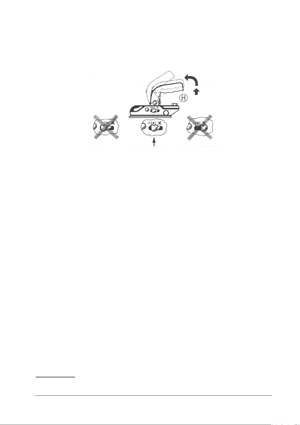
Figure 5.
Connecting:
Open the coupling housing by pressing the locking button on the handle H and
moving the handle upwards. Place the opened coupling on the ball of the towing
vehicle’s tow bar and release the handle. The handle should automatically slide back
to the starting position. The coupling is automatically closed and locked in place.
Make sure the coupling is in the right position >>+<< (see figure 5). The tow ball
must not be visible when the trailer is connected. Fasten the safety cable (see figure
11) and insert the plug in the towing vehicle. Raise the support wheel and secure it in
position parallel to the direction of travel (the support wheel must not impede the
movement of the brake rod).
Always check whether the lights work before driving.
Disconnecting:
Lower the support wheel. Disconnect the safety cable and the plug. Open the
coupling housing by pressing the locking button on the handle H and moving the
handle upwards. Lift the coupling off the towing vehicle’s tow bar. Pay particular
attention when disconnecting on an incline (once the towing vehicle is stationary,
apply the handbrake or use the wheel blocker, if fitted)
Only drive in the >>+<< range
3.2.2 LOADING THE TRAILER
Maximum load
The maximum load must not be exceeded. The maximum load is equal to the unladen
weight of the trailer plus the load capacity.
Maximum load: Unladen weight + load capacity
Wagenbouw HAPERT 22
Page 23

Unladen weight: The weight of the trailer when ready to be used, i.e. with spare
parts and tools that are normally included, but without a load.
Load capacity: The maximum permitted load weight.
Weight distribution:
To ensure the brakes work properly and to have good road handling, the centre of
gravity must be as close as possible to the axle.
Heavy objects must be placed as much as possible above the axle.
Lighter objects should be distributed evenly across the cargo bed.
The load should be divided over the right-hand and left-hand halves of the trailer as
evenly as possible.
Avoid point loads.
The load must always be properly secured. Each country has its own regulations.
Make sure the trailer meets the applicable requirements.
When loading and unloading the trailer, it must always be connected to the towing
vehicle.
Figure 6
Maximum support wheel load:
The maximum static load for a sliding support wheel is 150 kg. The maximum static
load for a foldable support wheel is 250 kg. The maximum load must not be exceeded.
Attention!
Wagenbouw HAPERT 23
The trailer has been designed, constructed and tested for the loads
shown in the accompanying documents and on the type
plate/construction plate attached to the front of the trailer. Overloading
the trailer can result in permanent damage, for which the manufacturer
accepts no liability.
Page 24

Tying down/securing the load:
The load must always be tied down and secured properly on the trailer using binders
that are suitable for this specific purpose
The tie rings, which are fitted as standard and are TÜV-certified according to quality
mark DIN EN 75410-1, must be used to secure a load.
Figure 7
For tying down the load, only use reliable ropes that are specifically designed for this
purpose and that comply with standard EN 12195-2.
The maximum load that the tie rings fitted on the sides of the trailer (see figure 7) can
take is 1,000 kg (daN)
Supports
Supports fitted under the chassis can be extended when loading the trailer.
How the supports work: After releasing the locking pin, the supports can be rotated
90°
Rotatable by 90˚ downwards and re-secured in position with the locking pin.
Using the handle supplied with the trailer, the support should
be lowered until it is approx. 5 cm above ground level when
the trailer is empty (see figure 8).
The 5 cm gap is needed to compensate for the spring of the axles. If the supports are
lowered completely, they will take the entire weight of the load and can become
damaged. On soft ground, suitable plate material has to be laid under the supports.
Before driving off, the supports have to be secured in their top position and, if
necessary, rotated 90° so that they lay parallel to the chassis (see figure 9).
Wagenbouw HAPERT 24
Page 25

Figure 8
Figure 9
Ball thrust:
The ball thrust is one of the most important criteria for the road handling of the trailer
and, therefore, the entire vehicle combination.
The maximum permitted ball thrust (see the specifications of your tow bar or vehicle
and the type plate on your trailer) may not be exceeded. The ball thrust can be
increased or reduced by moving the load further forwards or backwards, respectively.
The optimal ball thrust is close to the maximum ball thrust. A negative ball thrust (i.e. an
upwards force applied to the tow bar) is strictly forbidden.
Carelessly loading the trailer may result in a risk of slipping or swerving. Adjust your
speed to the condition of the road surface and the load. This is particularly important in
corners.
Make sure the wheels do not wobble and the tyres are balanced.
Coupling height (with regard to the towing vehicle):
Another important element which influences the vehicle combination’s road handling
(particularly for tandem trailers) is the height of the coupling. The trailer’s coupling
height and that of the towing vehicle must not differ by too much. The vehicle
combination’s road handling is influenced by the difference in coupling height. A
dangerous situation may arise if the towing vehicle’s coupling height is considerably
lower than that of the trailer, because this results in a negative ball thrust.
Wagenbouw HAPERT 25
Page 26
Relationship between load, tyre pressure, ball thrust and coupling height:
Poor road handling is unavoidable if a trailer creates a negative ball thrust because it is
poorly loaded and if it is connected to a towing vehicle with a lower coupling height. If
this is combined with a tyre pressure which is too low (see 5.1.1), then a dangerous
situation may arise. For that reason, all the warnings given above must be observed.
3.2.3 BEFORE PULLING AWAY
Raise the support wheel and secure it in position. The support wheel must always
point in the direction of travel (the support wheel must not impede the movement of
the brake rod).
Check the coupling. The coupling housing must completely enclose the ball and
must be secured. Make sure the coupling is in the right position >>+<< (see figure 5).
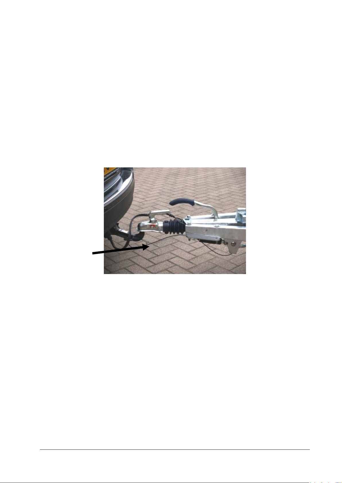
Attach the safety cable to the towing vehicle (see figure 11).
Safety cable
Figure 11
Insert the lighting plug.
Regularly check the tyre pressure (see table 5.1).
Make sure the load is evenly distributed and properly secured.
Check the lights: indicators, rear lights, brake lights (the load must never obscure the
view of the lights).
Before driving off, make sure any wheel blockers have been removed and that the
handbrake on a braked trailer has been released.
Check whether the cargo bed is secured to the chassis (only for type INDIGO HT
and LT).
Check whether all the locking pins are fitted and secured in place (only for type
COBALT HM and COBALT+).
Make sure the supports are secured in their top position and, if necessary, rotated
90° so that they lay parallel to the chassis (see figure 9).
The trailer has an auto-reversing mechanism. This means that if you reverse, the
overrun brake does not have to be blocked.
Wagenbouw HAPERT 26
Page 27

3.2.4 TIPPING THE TRAILER
Find out whether the tipping trailer has a hand pump, an electric pump (possibly with a
battery) or both.
Warning!
Only turn on the hydraulic system when you have made
absolutely sure that nobody is in the danger zones around
the trailer. Attention:
Make sure nobody is in the location where the load is to
be tipped.
Make sure nobody is on the trailer.
Pay attention to the risk of becoming trapped between the
cargo bed and the chassis.
Warning!
Do not use the tipping system on a steep incline.
1. Only use the tipping system when the trailer is stationary and connected to the
towing vehicle.
Make sure the trailer’s handbrake has been applied.
2. Lower the support wheel.
3. Make sure the load is no longer secured.
4. To tip backwards:
- Unlock the two locking pins on the two front corners of the trailer (only for type
COBALT HM and COBALT+).
- Unlock the rear flap.
To tip to the left (only for type COBALT HM and COBALT+):
- Fit the two locking pins to the two left-hand corners of the trailer.
- Unlock the left-hand flap.
To tip to the right (only for type COBALT HM and COBALT+):
- Fit the two locking pins to the two right-hand corners of the trailer.
- Unlock the right-hand flap.
Wagenbouw HAPERT 27
Page 28

Warning!
Before tipping, always check that:
- The load is no longer secured.
For type COBALT HM and COBALT+:
- The correct two locking pins are in place.
- The correct side flap or the rear flap is unlocked.
For types COBALT HB and INDIGO HT and INDIGO LT:
- The rear flap is unlocked.
5.0 Tipping using the hand pump:
To tip the cargo bed: place the hand pump’s valve in the “raise” position and use the
pump lever to pump until the desired height is reached.
To lower the cargo bed: place the hand pump’s valve in the “lower” position until the
cargo bed touches the chassis and then place the valve back in the “raise” position.
5.1 Electric tipping:
Use the key of the main power switch to turn on the system. (See figure 1) Turn the key
clockwise to activate the electrical system. The on/off button on the control panel needs
to be pressed 1 time to activate the control panel. To raise the cargo bed: keep the
relevant button on the control panel (see figure 2) pressed until the desired height is
reached.
To lower the cargo bed: keep the relevant button on the control panel pressed until the
cargo bed has returned to its rest position.
Turn the system off using the key in the main switch - turn the key to the left and
remove it!
See 3.1.1 and 3.1.2 for electric tipping using the remote control.
5.2 Electric tipping in combination with an emergency pump:
Electric operation: See “Electric tipping” for additional operating instructions.
Emergency pump operation: To tip the cargo bed: use the pump lever to pump until
the desired height is reached.
To lower the cargo bed: rotate the button until the cargo
bed rests on the chassis.
After the cargo bed has been lowered, place the rotary
button back in the “raise” position.
(Rotate closed/see figure 12)
Wagenbouw HAPERT 28
Page 29

Rotary button
Emergency pump lever
Figure 12
6. Lock the side flap or the rear flap.
Make sure the drive-on ramp is secured (only for type INDIGO HT and
INDIGO LT).
7. Use the two locking pins to secure the cargo bed to the chassis (only for type
COBALT HM and COBALT+) or lock the cargo bed to the chassis (only for type
INDIGO HT and INDIGO LT).
8. Raise the support wheel.
3.3 MAINTENANCE
Warning!
When working under the cargo bed:
Always support the cargo bed!
Maintenance by the user/service personnel
Wheel attachment:
After the first journey, check whether the wheel bolts are still sufficiently tightened. If
necessary, retighten them. Use the tightening torques table in the Specifications
chapter (5.1.1) to find the correct torque. Check the bolts every time a wheel has
been loosened, for example, to change a tyre (tighten the wheel bolts crossways).
Check the plug and the lights (dirt, corrosion and damage).
Check the tyres (tyre pressure, wear and damage).
Ball coupling:
Regularly clean and grease all sliding surfaces and bearing points.
Wagenbouw HAPERT 29
Page 30

Figure 13
Hydraulic pump oil level:
Check the hydraulic oil level and, if necessary, top it up.
For an electric pump: when the cylinders are in the highest position, the level must
be up to 10 cm below the edge of the cover.
For a hand pump: when the cargo bed is down, the level must be up to 1 cm below
the edge of the cover.
Battery, charge it if necessary:
A disconnected battery should be stored in a dry, frost-free location in your
warehouse (this is vital to reduce self-discharge to a minimum).
After a few months, the battery will have discharged itself and its condition should,
therefore, be checked. At 12.2 V (this is 80% of its capacity), the battery needs to be
recharged with a charger that has a capacity equal to at least 10% of the battery’s
capacity (e.g. a 90 Ah battery must be recharged with a charger of at least 8 A and
no more than10 A in order to obtain the best results).
This also applies to batteries that are installed in products in your showroom, so
please check their condition regularly and, if needed, recharge to 12.7 V (100%
battery charge).
If you neglect to do this, battery sulphation will irrevocably occur (lead sulphate that
attaches itself to the plates) and recharging will no longer be possible.
Sulphated batteries are not covered by warranty.
Attention!
You should never charge the battery with a quick charger.
Always use a trickle charger.
Depending on the type of trailer, it may have a plug socket for a battery charger.
Wagenbouw HAPERT 30
Page 31

Lubricating the overrun system:
Lubricate the grease nipples with grease (see figure 14) and the sliding parts with oil.
Handbrake Grease nipples
Ball coupling Safety cable Figure 14
3.4 CLEANING
The trailer may be hosed down with water. We recommend that you do so if the trailer
has been in contact with salt (brine) or acids, as the zinc coating can be permanently
damaged by such substances. For new vehicles of which the zinc coating has not yet
fully hardened, white spots (white rust) or black spots may appear if the trailer is not
cleaned frequently enough. However, the protective effect of the zinc coating is not
reduced by the spots. To try to prevent these spots on hot-dip galvanised components,
you can take measures to ensure there is sufficient air circulation during storage, so no
water film develops between the metal surfaces.
Always make sure the electrical components do not come into contact with water or
other liquids!
Wagenbouw HAPERT 31
Page 32

4. OTHER MAINTENANCE WORK
The work specified here may only be carried out by service personnel, as described in
2.4.2.
4.1 REPAIR AND MAINTENANCE
4.1.1 MAINTENANCE INSTRUCTIONS
The trailer must be inspected at least once a year by an official HAPERT dealer. The
HAPERT dealer will check and repair the trailer in accordance with the “BOVAGAanhangwagenbedrijf” regulations (BOVAG Trailer Company).
If faults arise in the meantime, a dealer must be contacted as soon as possible.
4.1.2 REPAIRING/REPLACING PARTS
During the warranty period, repairs may only be carried out under the supervision of
HAPERT or an official HAPERT dealer.
All replacement parts must always have the same specifications as the originals.
All parts can be ordered from an official HAPERT dealer.
The trailer is built from both standard parts (generally available on the market) and
specific components (especially made for the trailer).
Standard parts:
Only use original parts.
If you have any doubts about the specifications, ask HAPERT or an official HAPERT
dealer.
Specific parts:
Only use replacement parts provided by HAPERT or an official HAPERT dealer.
Warning!
Deviating from the instructions given above may result in
damage to the trailer. HAPERT or an official HAPERT dealer
cannot accept any liability in this respect.
Wagenbouw HAPERT 32
Page 33

5. SPECIFICATIONS
5.1 TRAILER AND WEIGHTS
See the Media section at WWW.HAPERT.COM for all the dimensions and weights.
5.1.1 WHEELS AND TYRES
Wheel bolt specifications:
Screw thread Spanner size Max. tightening moment
mm mm Nm
M 12 x 1,5 17 (19) 80 - 90
M 14 x 1,5 19 110 - 120
Optimal tyre pressure:
The optimal tyre pressure depends on the type of tyre. Any garage can give you this
information. Only use Wagenbouw HAPERT tyres or inquire at Wagenbouw HAPERT
or an official HAPERT dealer.
TYRE SIZE TYRE PRESSURE MAX. LOAD
155/80R13 2,9 42 500
165R13C 4,5 65 710
185/70R13 3 44 650
175R14C 4,5 65 775
185R14C 4,5 65 900
155/70R12C 6,5 95 900
195/50R13C 6,5 95 900
195/55R10C 6,2 90 750
205/70/R15C 3,8 55 900
145/70R13 3 44 425
18.5x8.5-8 3,4 50 425
185/70R13C 6 85 950
BAR PSI KG.
5.1.1.1 MOUNTING BRAKE SYSTEM, AXLES AND DRAWBAR
Screw thread Spanner size Max. tightening moment
mm mm Nm
M 12 Kl. 8.8 17 (19) 80 - 90
M 12 Kl. 10.9 17 (19) 110 - 120
Wagenbouw HAPERT 33
Page 34

5.1.2 ELECTRICAL SYSTEM
13-pole plug connection diagram:
Figure 15
7-pole plug connection diagram:
Figure 16
INDICATION COLOUR NAME
1 Yellow Left indicator
2 Blue Fog lamp
3 White Earth (for poles 1-8)
4 Green Right indicator
5 Brown Right rear light
6 Red Left and right brake lights
7 Black Left rear light
8 Grey Reversing light
9 Brown/blue Continuous current
10 Brown/red Battery charger (plus)
11 White/Red Battery charger earth
12 Free
13 White/black Earth (for poles 9-12)
INDICATION COLOUR
L Yellow Left indicator
54G Blue Fog lamp
31 White Earth
R Green Right indicator
58R Brown Right rear light
54 Red Left and right brake lights
58L Black Left rear light
NAME
Wagenbouw HAPERT 34
Page 35

5.2 TIPPING SYSTEM
5.2.1 TIPPING RANGE
Tipping range, tipping backwards To the end of the cylinder
Tipping range, tipping sideways (only type
COBALT HM and COBALT+)
Until the safety cable is tight or by
means of a stop switch (electric
operation)
5.2.2 HYDRAULIC PUMP
Hand pump COBALT
HB, HM, and COBALT+
Nominal pressure 180 bar 250 bar 170 bar
Pressure relief valve
setting
Oil reservoir
Volume
Effective volume
Hydraulic oil Tellus 46, Shell HM46 or
Battery
Type
Capacity
Electric motor capacity N/A N/A 2 kW
Maximum sound level <70 dB(A) <70 dB(A) <70 dB(A)
220 bar 300 bar 200 bar
5 litres
4.5 litres
similar
N/A N/A
Hand pump INDIGO
HT and INDIGO LT
(double-acting)
1 litre
1 litre
Tellus 46, Shell
HM46 or similar
Electric pump COBALT HB,
HM, COBALT+ and INDIGO
HT
5 litres
4.5 litres
Tellus 46, Shell HM46 or
similar
12 V starter battery
90 Ah
5.3 PHYSICAL CONDITIONS OF USE
Ambient temperature:
* Working
* During transport/storage
Relative humidity (RH) 30% to 95%, non-condensing
Lighting E4 / normal ambient lighting
The trailer is not suitable for use in an explosion-hazardous environment.
-5 to +40 degrees Celsius (with
hydraulic system)
-25 to +40 degrees Celsius
-25 to +55 degrees Celsius
Wagenbouw HAPERT 35
Page 36

5.4 APPLICABLE DIRECTIVES AND STANDARDS
Trailers with a hydraulic tipping system have CE marking. This CE marking concerns
the trailer’s tipping system. The CE marking means that the tipping system meets the
applicable European guidelines concerning health and safety. The "Declaration of
Conformity" (see page 45) specifies the respective directives.
The applicable standards are also specified in the "Declaration of Conformity". The
trailer also complies with the provisions of European Directive 2007/46/EC and the
Netherlands Road Transport Directorate (Rijksdienst voor het Wegverkeer) has issued
the required type approval.
Wagenbouw HAPERT 36
Page 37

6. MARKINGS ON THE TRAILER
6.1 TYPE/CONSTRUCTION PLATE
The trailer complies with the provisions of European Directive 2007/46/EC and the
Netherlands Road Transport Directorate (Rijksdienst voor het Wegverkeer) has issued
the required type approval, which means a type/construction plate has to be fitted on
the trailer. The type/construction plate lists the following information (see figure 17):
DESCRIPTION TRAILER DETAILS
Name of manufacturer See trailer type plate
Approval no. See trailer type plate
Identification no. See trailer type plate
Max. total weight See trailer type plate
Max. ball thrust See trailer type plate
Max. axle load 1 See trailer type plate
Max. axle load 2 See trailer type plate
Max. axle load 3 See trailer type plate
Max. axle load 4 See trailer type plate
Type See trailer type plate
Manufacturer See trailer type plate
Figure 17
Location of the type/construction plate and chassis number: at the front on the righthand side (see figure 18).
Wagenbouw HAPERT 37
Page 38

Type/construction plate
Identification number
Figure 18
Location of the type plate of an ECE-approved tow pole: against the tow pole
For trailers with a pipe tow shaft, it is located on the shaft.
(See figure 19)
Tow pole type plate
Figure 19
All warning stickers and type plates placed on the trailer must be legible at all
times. Replace stickers and type plates that are damaged or no longer legible.
Wagenbouw HAPERT 38
Page 39
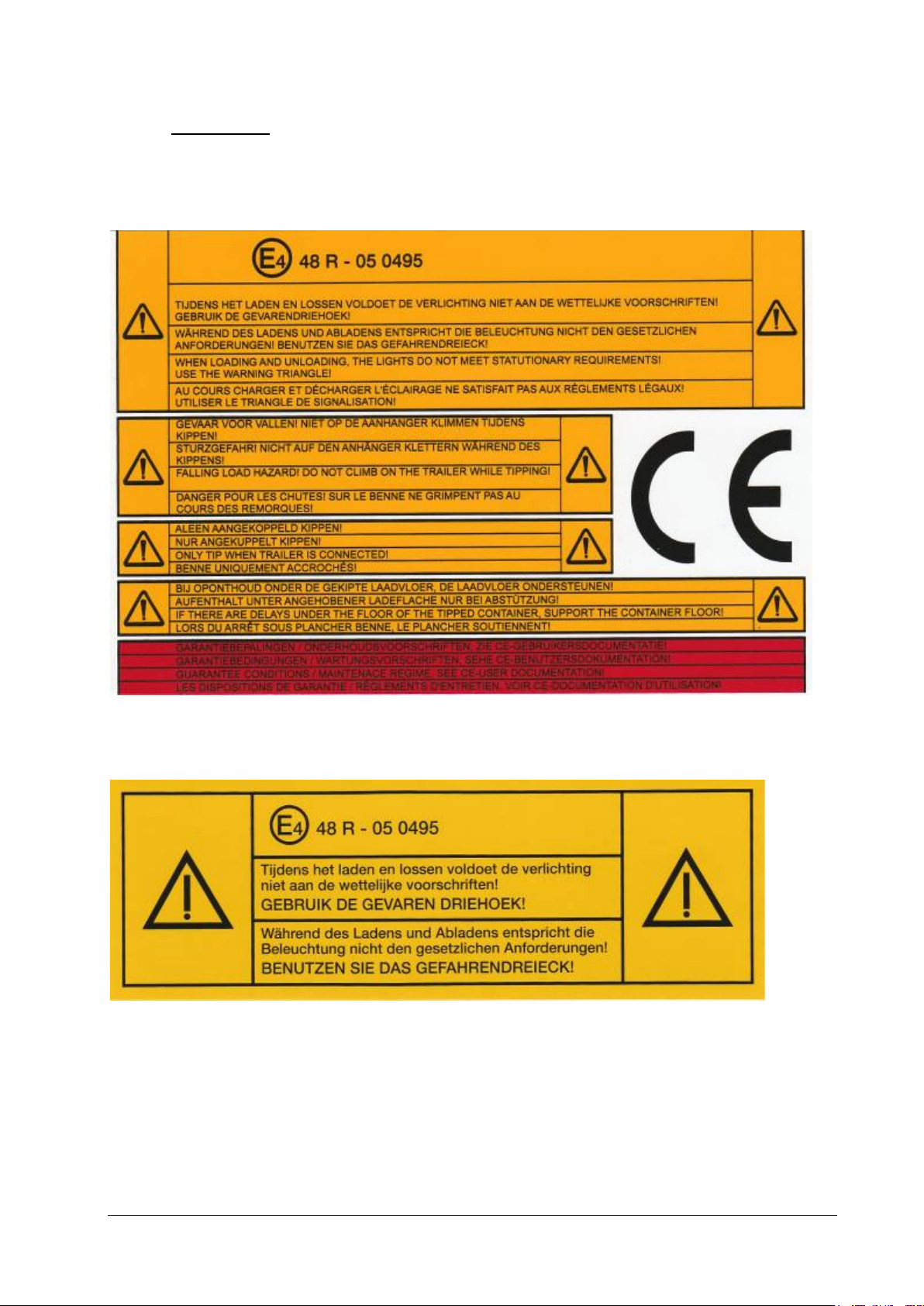
6.2 WARNINGS
The following warnings are placed on the front of a trailer with a hydraulic tipping
system:
The following warning is placed on the rear of a trailer with lights that can be obscured:
Wagenbouw HAPERT 39
Page 40

6.3 VEHICLE DETAILS
Fill in the trailer details below:
Type of trailer
Trailer dimensions
Chassis number
Max. total weight
HAPERT dealer stamp
Wagenbouw HAPERT 40
Page 41

7. SERVICES
This trailer is a road vehicle and has been constructed from parts that require
continuous maintenance. For that reason, this trailer is always delivered with a
handover inspection and a delivery confirmation, which must be completed by the
dealer and the customer. The trailer must undergo its first service after no more than 6
months and then after every 12 months. Observing the service requirement (performing
all the required services for the first 24 months) is compulsory for the warranty to
remain valid. Also see “Warranty and liability” in this manual.
Service on delivery Max. 6 months-after-delivery service
Date
HAPERT dealer stamp
Signature
Date
HAPERT dealer stamp
Signature
Wagenbouw HAPERT 41
Page 42
1st year service 2nd year service
Date
HAPERT dealer stamp
Signature
At least 1 year after the delivery
service
3rd year service 4th year service
Date
HAPERT dealer stamp
Signature
At least 1 year after the 2nd service
Date
HAPERT dealer stamp
Signature
At least 1 year after the 2nd service
Date
HAPERT dealer stamp
Signature
At least 1 year after the 3rd service
Wagenbouw HAPERT 42
Page 43

5th year service 6th year service
Date
HAPERT dealer stamp
Signature
At least 1 year after the 4th service
7th year service 8th year service
Date
HAPERT dealer stamp
Signature
At least 1 year after the 6th service
Date
HAPERT dealer stamp
Signature
At least 1 year after the 5th service
Date
HAPERT dealer stamp
Signature
At least 1 year after the 7th service
Wagenbouw HAPERT 43
Page 44

9th year service
Date
HAPERT dealer stamp
Signature
At least 1 year after the 8th service
11th year service 12th year service
Date
HAPERT dealer stamp
Signature
At least 1 year after the 10th service
10th year service
Date
HAPERT dealer stamp
Signature
At least 1 year after the 9th service
Date
HAPERT dealer stamp
Signature
At least 1 year after the 11th service
Wagenbouw HAPERT 44
Page 45

EU DECLARATION OF CONFORMITY
We Wagenbouw HAPERT BV
Handelsweg 13
5527 AL Hapert
The Netherlands
Tel: +31 (0) 497 38 68 68
Fax: +31 (0) 497 38 68 82
Internet: www.hapert.com
E-mail: info@hapert.com
Hereby declare under sole responsibility:
1- We are the manufacturer of the following machine to which this declaration
applies: Trailer tipping system
Brand: HAPERT
Types: COBALT HB
COBALT+
COBALT HM
INDIGO LT
INDIGO HT
Function: Tipping a cargo bed with a load.
Serial number: all serial numbers of these types.
2- The machine has been designed and built in accordance with the requirements of
Machinery Directive 2006/42/EC.
3- The machine also complies, when the occasion arises, with the requirements of
the following EU directives: EMC directive 2004/108/EC.
4- The machine has been designed and built in accordance with the requirements of
the (European) standards or normative documents:
NEN EN 1037:1996+A1: 2008 Prevention of unexpected start-up
NEN EN 1853:1999+A1: 2009 Agricultural machinery. Trailers with tipping body. Safety.
NEN EN 4413:2010 Hydraulic fluid power - General rules and safety
requirements for systems and their components
NEN-EN-ISO12100-1:2010 Safety of machinery - General principles for design - Risk
assessment and risk reduction.
Signed in Hapert
Date: September 2013
.....
Signed by: A.J.H. Saris
Position: Director
Wagenbouw HAPERT 45
 Loading...