

HANYOUNG NUX TD510, TD510-1N Operation Manual


Notice
This operation manual is protected by copyright and has all rights concerned.
Without prior consent from Hanyoung Nux Co., Ltd., any part of this document will
not be copied, reproduced, modified, or translated into another language.
This operation manual is provided "as is" and may be subject to changes without
prior notice.
Regarding this manual, Hanyoung Nux Co., Ltd. does not assure anything
including but not limited to implied marketability or conformance to certain purpose.
The accompanied programs are protected by copyright.
All product names, which are used in this document and product, are product
names, service marks, trademarks, or registered marks of the owners.
Hanyoung Nux Co., Ltd.
28, Gilpa-ro 71beon-gil, Nam-gu, Incheon, Korea
TEL : (82-32)876-4697
FAX : (82-32)876-4696
E-mail. overseas@hynux.com

Before starting
1. Checking of components
2. Safety cautions
3. Warranty
2
4
4
Installation
Operation
Screen block diagram
Function setting
Program
1. Installation site & cautions
2. How to install 5
3. Exterior & panel dimensions
4. Wiring
5. Terminal connection diagram
1. Name of section
2. Button operation
3. How to control numeric input panel
4. How to control character input panel
5. Name of control
1. Screen block diagram
1. Operation screen
2. Operation setting
3. PV graph view
4. Time/schedule setting
5. Event
1. Pattern setting
2. Pattern management
3. Pattern name setting
4. Pattern alarm setting
5. Time signal setting
6. Pattern graph
10
11
13
14
14
15
16
17
19
32
37
39
40
44
47
49
50
51
52
5
8
InstallationBefore starting
Operation
Screen block
diagram
Function setting Program System setting Specifications
System setting
Specifications
1. Sensor input setting
2. Control/transmission output
3. PID setting
4. Inner signal
5. ON/OFF signal
6. System alarm
7. DI configuration
8. DO configuration
9. System
1. Input specifications
2. Hardware specifications
3. Display specifications
4. Memory specifications
5. Installation environment
6. Engineering unit
54
56
58
61
64
66
67
72
78
82
82
85
85
85
86
1
Before starting
Thank you for purchasing Hanyoung Nux programmable temperature controller(Model: TD510).
This programmable temperature controller(Model: TD510) is a unit to control temperature consisting
of display and control. The display can be attached to a panel or VESA-mounted and is
connected to the control for communication. The control consists of power, control, and input/
output modules and can be fixed on DIN rail or attached on a panel using screws.
The operation manual describes product functions, how to install, cautions, and how to use. Read
and understand this document before starting the product.
Make sure that this operation manual will be delivered to an end user and kept in an accessible
location (This operation manual may be subject to changes for improvement and functional
changes without prior notice).
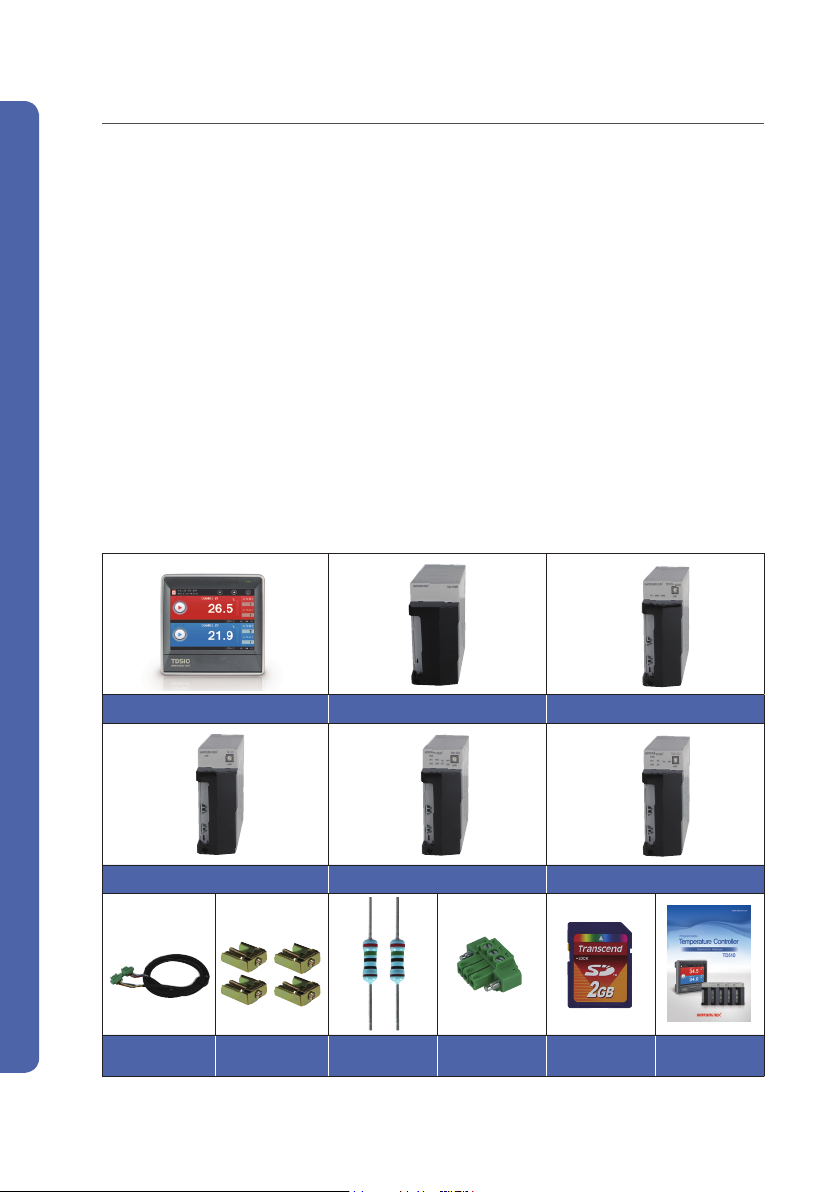
1. Checking of components
First of all, check the specifications referring to your order and see if there is any exterior damage or
missing component.
▶ Component
Display(TD510-1) Power module(TM-PWR) Control module(TD510-MAIN)
Programmable Temperature & Humidity Controller
Input module(TM-DI) Output module(TM-DO) Input/output module(TM-DIO)
Communication
cable(1.5 m)
Bracket 4EA
250-Ω resistor
2EA
3P communication
Connector
2
SD card
Operation
manual
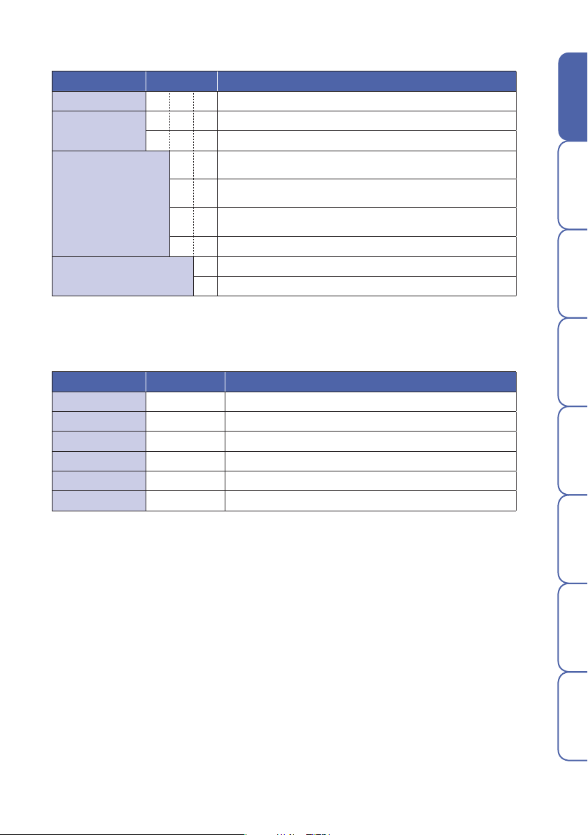
▶ Model name
Model Code Description
TD510- ☐ ☐ ☐ Programmable temperature controller
Display
Input/output
Language
※ This product consists of the display and control(power, control, input, and output modules).
(Up to 32 contact input/output points, respectively)
1 Display(5.7" TFT LCD)
N None
1
2
3
N No input/output
8 input points/6 output points(1 module)+Power module
+Control module
8 input points/14 output points(2 modules)+Power module
+Control module
16 input points/16 output points(3 modules)+Power module
+Control module
S Korean, English, and Chinese(Simplified)
T Korean, English, and Chinese(Traditional)
▶ Components
Product Model Description
Display TD510-1N☐ Display(5.7" TFT LCD)
Control module TD510-MAIN Temperature 2-channel control module
Power module TM-PWR Power module
Input module TM-DI Module with 16 input points
Output module TM-DO Module with 8 output points
Input/output module TM-DIO Module with 8 input and 6 output points
Before starting
Installation
Operation
Screen block
diagram
Function setting Program System setting Specifications
3

2. Safety cautions
The cautions are categorized into Danger, Warning, and Caution according to seriousness.
Danger
Warning
Caution
● The operation manual may be subject to changes for improvement without prior notice.
● To protect and secure the product and system connected, use the product according to the
safety instructions of this manual.
● We are not liable for any damage caused by negligence or not following the instructions.
● To protect and secure the product and system connected, install any separate or external circuit
outside of the product.
● Do not remove, repair, or modify it without prior consent. It may cause electric shock, fire, and
malfunction.
● Avoid any strong impact. It may cause damage or malfunction to the product.
● To disconnect the main power, install a switch or circuit breaker.
If not followed, it may lead to death or serious injury.
If not followed, it might lead to death or serious injury.
If not followed, it may lead to minor injury or damage to assets.
3. Warning
●
We are not liable for any condition other than those specified warranty conditions.
●
If a user or third party is damaged in using this product due to unforeseeable defect or natural
disaster, we are not liable for any loss or indirect damage.
●
The warranty is valid for 1 year from a date of purchase and is applicable to any failure found
in normal use conditions.
●
For any failure found after the warranty period, paid service may be provided according to our
regulations.
Programmable Temperature & Humidity Controller
●
Any of followings will be repaired at a cost even if it is fund in the warranty period.
•Failure attributable to user (e.g. Initialization due to lost password)
•Failure attributable to a natural disaster (e.g. fire, flood, etc.)
•Failure attributable to relocation after installation
•Failure attributable to unauthorized modification or damage
•Failure attributable to unstable power supply
●
If you require A/S, contact your dealer or Hanyoung Nux Co., Ltd..
4

Installation
1. Installation site & cautions
Before starting
● It may cause electric shock so install in on the panel first.
● Avoid following locations.
• Where people might unintentionally contact a terminal
• Where there is strong vibration, impact, or electromagnetic field
• Where it is exposed to a corrosive or inflammable gas
• Where the temperature changes sharply or there is much humid, dust, or salt
• Where it is directly exposed to direct sunlight or the temperature is extreme
• Where there are combustibles around
● The case and front section are made of fire-retardant polycarbonate but do not install it directly on a
combustible.
● Keep away any device or wire that may cause noise. Enough preheating is required especially under
0℃. Keep away any heat-radiating device.
● For wiring, disconnect the entire power.
● This product works at 100 - 240 V a.c. / 50 - 60 ㎐ without special setting. Apply rating only.
It may lead to fire or electric shock.
● Do not touch it with wet hand. You may be electrically shocked.
● Follow conventional cautions in order to reduce the risk of fire, electric shock, and injury.
● For grounding, refer to how to install. (Grounding resistance : 100 Ω or less)
● Keep ventilation and the radiating hole free.
● The over voltage protective level is Category II(IEC 60664-1) and use environment is Pollution Degree.
● Do not use a sharp object or force to touch the screen.
● The external terminals(sensor input, communication, and control output terminals) must be connected
to separate circuits with at least reinforced insulation from dangerous voltage sections.
● To disconnect the main power, install a switch or circuit breaker.
Installation
Operation
Screen block
diagram
Function setting Program System setting Specifications
2. How to install
Before installing it, disconnect the power. Do not touch a terminal because it may lead to
electric shock.
Danger
●
Use 2-5mm thick panels.
●
Insert this device from the front of panel.
●
Connect dedicated clamps to the clamping grooves and fix them with bolts.
(Before fully tightening the clamps, position them in place).
5
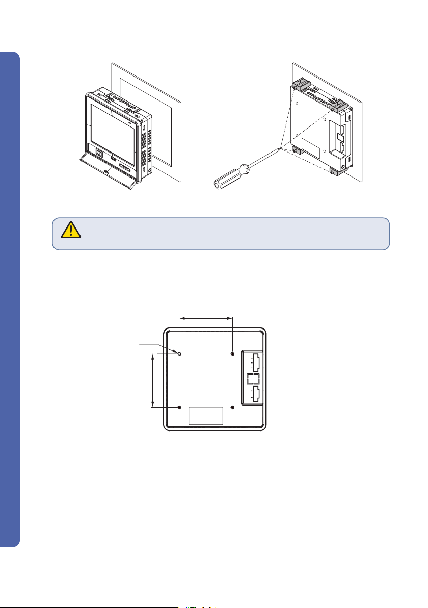
▶Display
(1) How to attach panel
Fig. 1) How to attach a panel
The tightening torque must be 0.5 N·m or less for clamping.
Forcible tightening may lead to deformation or damage.
Caution
(2) How to install VESA mount
Connect an M4 X 7L bolt into a VESA hole.
75.0
4-M4
+
1
DC 5V
2
3
COM1
4
75.0
5
6
7
COM2
8
Programmable Temperature & Humidity Controller
6

▶Control
TM-DO
ADR
PWR
RY2
RY6
RY1
RY5
RY3
RY7
RY4
RY8
TM-DO
ADR
PWR
RY2
RY6
RY1
RY5
RY3
RY7
RY4
RY8
TM-DO
ADR
PWR
RY2
RY6
RY1
RY5
RY3
RY7
RY4
RY8
TM-DO
ADR
PWR
RY2
RY6
RY1
RY5
RY3
RY7
RY4
RY8
1) How to install DIN rail
Before starting
Ⓐ
Installation
Ⓑ
Operation
① Connect the top hook(A) of bottom of
floor to the DIN rail and press it(B) in
②
Check if it is fixed by pushing
up the mounting bracket.
order to install it.
●
How to install module
TD510 series module can connect up to 7 units. Any module must be installed vertically.
TM-DO
PWR
RY2
RY1
RY3
RY4
RY6
RY5
RY7
RY8
ADR
TM-DO
PWR
RY2
RY1
RY3
RY4
RY6
RY5
RY7
RY8
ADR
① Push a module aside
in order to connect it to a
connector.
TM-DO
③
PWR
RY2
RY1
RY3
RY4
RY6
RY5
RY7
RY8
ADR
TM-DO
PWR
RY2
RY1
RY3
RY4
RY6
RY5
RY7
RY8
ADR
TM-DO
PWR
RY2
RY1
RY3
RY4
RY6
RY5
RY7
RY8
ADR
TM-DO
PWR
RY2
RY1
RY3
RY4
RY6
RY5
RY7
RY8
ADR
② Fix a module on
both ends using
stoppers.
Screen block
diagram
Function setting Program System setting Specifications
7

2) How to attach panel
POWER용 MAIN용
① Referring to the hole dimensions on the left, find where to install it.
② Push outside the top and bottom hooks for fixing screws at the bottom of modules.
③ Fix it with an M3 screw.
●
POWER
●
Main, input/output, input, and output
Ø4.2
113
4.2
5.5
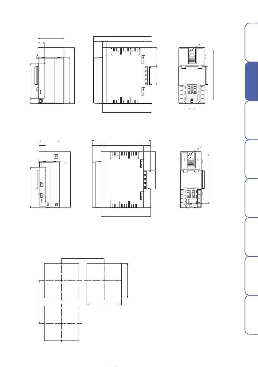
3. Exterior & panel dimensions
▶Display
(Unit : ㎜)
145.0
145.0
42.3
8.8
4-M4
75.0
35.5
75.0
24.7
Ø4.2
113
4.2
+
1
DC 5V
2
3
COM1
4
5
6
7
COM2
8
5.5
Programmable Temperature & Humidity Controller
8
145.0
145.0
8.8
42.3
+
1
2
3
4
5
-
DC 5V
6
7
8
COM1
COM2
75.0
75.0
24.7
35.5
4-M4
▶Power module
50.0
13.0
(Unit : ㎜)
Before starting
112.0
8.017.0
73.2
13.8
Ø4.2
36.3
107.0
67.0
88.0
10.0
95.0
▶Control, input, output, and input/output modules
40.0
13.0
77.0
88.0
▶Panel dimensions
107.0
(Unit : ㎜)
17.0
112.0
8.0
73.2
13.8
95.0
35
(Unit : ㎜)
36.3
35
95.0
4.2
Operation
Screen block
Installation
Ø4.2
95.0
diagram
Function setting Program System setting Specifications
170.0
170.0
138.0
+0.5
-0
138.0
+0.5
-0
9

4. Wiring
Before wiring, disconnect the power. Do not touch a terminal
because it may lead to electric shock.
Danger
▶ Power connection
Vinyl-insulated wire(0.9 - 2.0 ㎟ (KSC 3304)) must be used.
Too much noise may lead to damage or malfunction to the device.
Use line filter to remove the noise.
Caution
▶ FG wiring
Vinyl-insulated wire(2.0 ㎟ (KSC 3304)) must be used. It must be grounded at 3 points or
more with 100 Ω or less resistance.
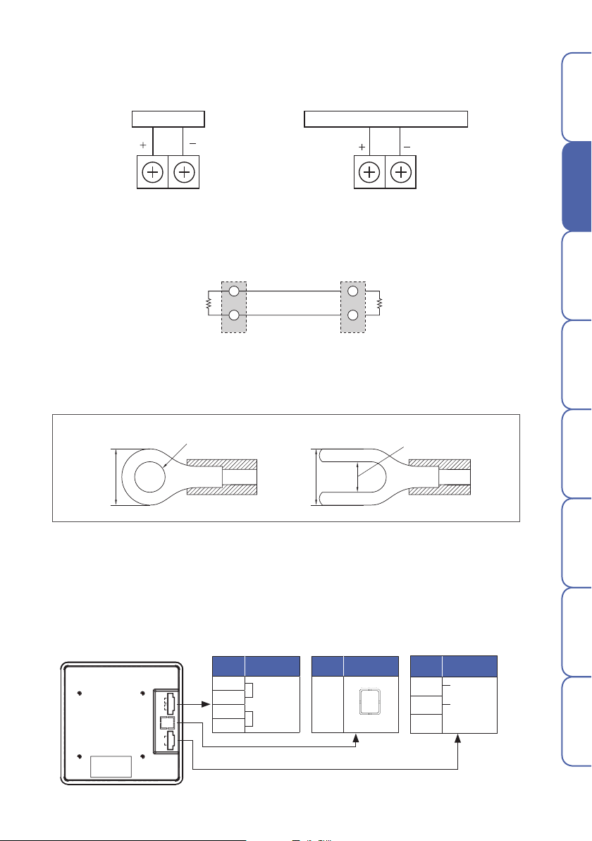
▶ Relay output wiring
Inductive load(L) including motor, solenoid, and external relay may lead to malfunction.
It must be connected in parallel with CR filter for AC circuit and diodes for DC circuit.
Caution
TD510 TD510
Relay output
terminal
Inductive load
Extern DC power
L L
Diode
Fig. 2) Connection of relay
Relay output
terminal
▶ Input wiring
Input wire must use shielded cable and be wired with certain distance from
the power and ground circuits. RTD sensor must be 3-wire type with the same wiring
Caution
resistance.
•Enclosure must be grounded at 3 points or more(100 Ω or less of grounding resistance)
using 2 ㎟ or bigger cable.
Programmable Temperature & Humidity Controller
●
•Input signal and output lines must be of shielded cable with 1 grounding point.
•Thermoresistor input must be wired with no resistance difference between 3 wires.
Caution
•Input/output signal line must be isolated from power line.
•To use current input, attach 250 Ω 0.1 % resistor at both ends of input terminal.
Sensor input
●
Thermoresistor input●Thermocouple input●DC voltage input●DC current input
T.C
Extern AC power
CR filter
Inductive load
10
Terminating
T.C
●
Thermocouple input
●
DC voltage input●DC current input
●
DO
TM-DO
DIDIOMAINPOWER
TM-PWR
ADR
PWR
RY2
RY6
RY1
RY5
RY3
RY7
RY4
RY8
COM1RUN COM2
TM-DIO
ADR
PWR
RY2
RY6
RY1
RY5
RY3RY4
TH510-MAIN
ADR
TM-DI
ADR
PWR
Wiring of temperature control and transmission output
●
Temperature control output
●
Temperature transmission output
SSR or SCR Recording and indicating instrument, etc..
▶ Communication wiring
Connect terminating resistors(100 - 200 Ω, 0.25 W) at both ends of communication cable.
Before starting
Installation
Operation
Master
Terminating
resistor
RTX+
RTX-
Fig. 3) How to wire for communication
▶ Terminal specifications
Power/Input/Output – M3 screw
3 ㎜ or more
6 ㎜ or
Fig. 4) Solderless terminal
5. Terminal connection diagram
▶ Display
Terminal
+
1
DC 5V
2
3
COM1
4
5
6
7
COM2
8
No.
1
2
3
4
Power
+
DC 5V
-
COM1 (control)
6 ㎜ or
Terminal
No.
TD510
RTX+
RTX-
resistor
Screen block
diagram
Function setting Program System setting Specifications
3 ㎜ or more
Ethernet
Terminal
5
No.
6
7
8
RS485
communication
RTX+
RTX-
11

DO
TM-DO
DIDIOMAINPOWER
ADR
PWR
RY2
RY6
RY1
RY5
RY3
RY7
RY4
RY8
COM1RUN COM2
TM-DIO
ADR
PWR
RY2
RY6
RY1
RY5
RY3RY4
TH510-MAIN
ADR
TM-DI
ADR
PWR
▶ Power module
DO
TM-DO
DIDIOMAINPOWER
ADR
PWR
RY2
RY6
RY1
RY5
RY3
RY7
RY4
RY8
TM-DI
ADR
PWR
DO
TM-DO
DIDIOMAINPOWER
ADR
PWR
RY2
RY6
RY1
RY5
RY3
RY7
RY4
RY8
DO
TM-DO
DIDIOMAINPOWER
ADR
PWR
RY2
RY6
RY1
RY5
RY3
RY7
RY4
RY8
TM-DIO
ADR
PWR
RY2
RY6
RY1
RY5
RY3RY4
TM-DI
ADR
PWR
DO
TM-DO
DIDIOMAINPOWER
ADR
PWR
RY2
RY6
RY1
RY5
RY3
RY7
RY4
RY8
TM-PWR
Terminal
No.
L
N
F.G
Power
100 - 240 V a.c.
50 - 60 ㎐
22 VA
▶ Control module
TH510-MAIN
ADR
TRX+ TRX-
Terminal
No.
1 10
2 11
3 12
4 13
5 14
6 15
7 16
8 17
9 18
1 2 3 4
POWER
5 V d.c.
COM1RUN COM2
Power
Terminal
CH1
+
H.OUT H.OUT
-
(SCR/SSR) (SCR/SSR)
+
C.OUT/RET C.OUT/RE T
-
A
RTD
B
+
T.C
mV/V
-
B
CH2
No.
+
-
+
-
A
B
+
T.C
-
B
RTD
mV/V
▶ Input module
TM-DIO
PWR
RY2
RY1
RY3RY4
RY6
RY5
Terminal
ADR
No.
1 10
Input(1~8)
Terminal
No.
Input(9~16)
▶ Output module
TM-DI
PWR
Terminal
No.
ADR
2 11
3 12
4 13
5 14
6 15
7 16
8 17
9 18
▶ Input/output module
TM-DI
PWR
ADR
Programmable Temperature & Humidity Controller
Terminal
Input(1~8)
No.
1
2 11
3 12
4 13
5 14
6 15
7 16
8 17
9 18
Terminal
No.
10
Output(1~6)
COM
COM
COM
Output(1~4)
Terminal
1 10
RY1
2 11
3 12
4 13
RY2
5 14
6 15
RY3
7 16
8 17
RY4
9 18
No.
Output(5~8)
RY5
RY6
RY7
RY8
12
Operation
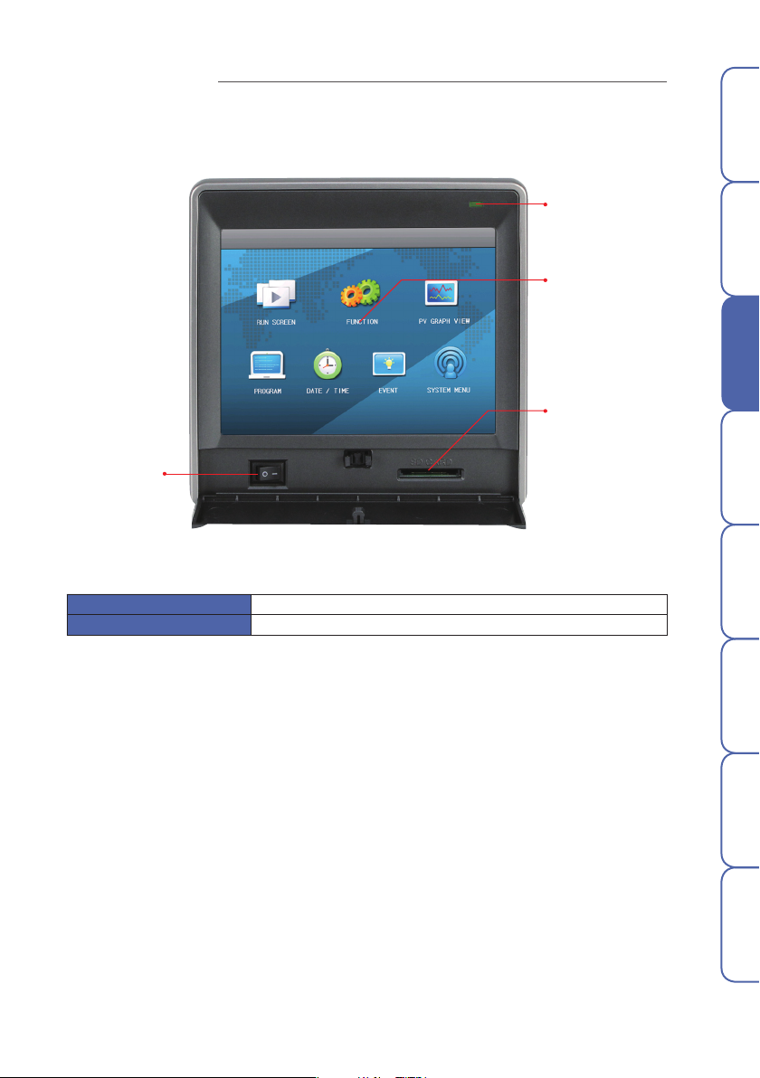
1. Name of section
Before starting
Power switch
Fig. 5) Main menu
[ Front LED ]
Back light OFF STOP (Red lamp ON), RUN (Red lamp OFF)
Back light ON STOP (Green lamp ON), RUN (Green lamp OFF)
Front LED
Display
SD card slot
Installation
Operation
Screen block
diagram
Function setting Program System setting Specification
13
2. Button operation
Run button Runs corresponding operation immediately.
Select button Selects one of items.
Input box
※ If the button is not active or can't be set, it sounds buzzer(beep) and doesn't run.
Displays ansets numbers and characters.
Press it to display the numeric or character input panel.
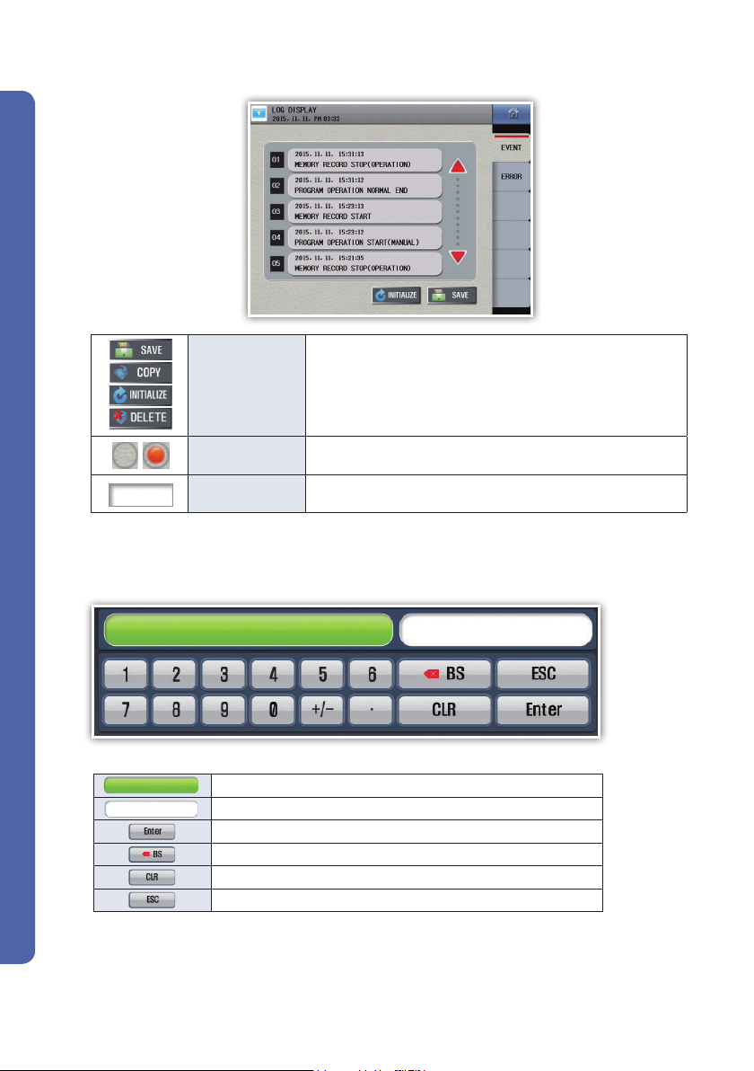
3. How to control numeric input panel
Programmable Temperature & Humidity Controller
※ If a setting range is exceeded, it sounds buzzer(beep) and doesn't run.
Displays parameter names and setting ranges.
Displays setting values.
Registers setting values.
Remove the last digit of setting value.
Remove the entire setting value.
Cancel setting and hide input panel.
Fig. 6) Numeric input panel
14
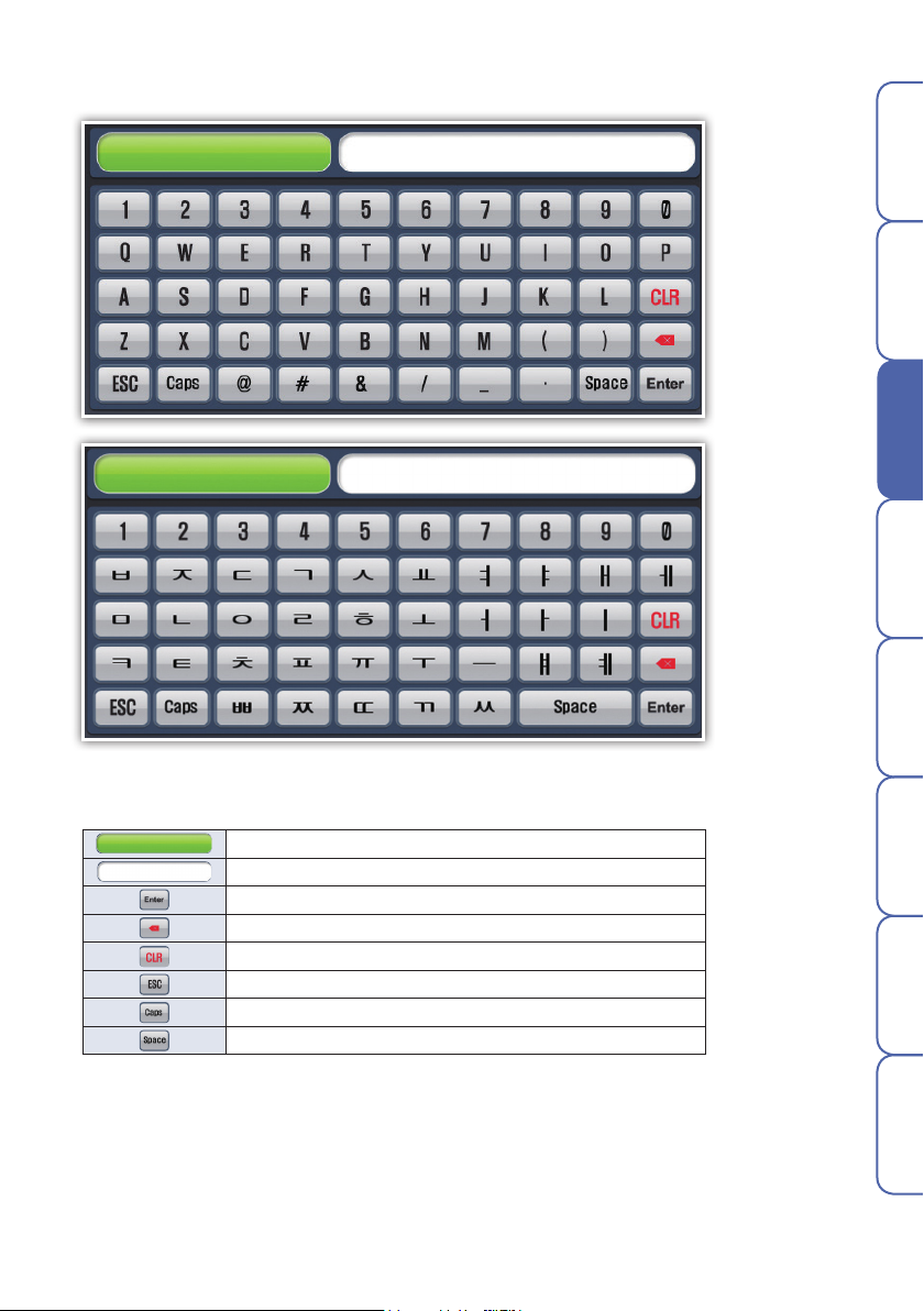
4. How to control character input panel
Before starting
Installation
Operation
Screen block
diagram
Function setting Program System setting Specification
Fig. 7) Character input panel
Displays parameter names.
Displays setting characters.
Registers setting characters.
Remove the last digit of setting characters.
Remove the entire setting value.
Cancel setting and hide input panel.
Switches between Korean and English upper or lower cases.
Blank.
15

5. Name of control
▶ Control module
[ LED specifications ]
RUN Lamp ON with power connected. Lamp OFF with power disconnected.
COM1 Displays communication state of the display and control. (OFF when OK.)
COM2 Displays communication state of the control and I/O. (OFF when OK.)
▶ Input/output module
[ LED specifications ]
PWR Lamp ON with power connected.
RLY1 ~ RLY8 Lamp ON with corresponding DO operation.
Programmable Temperature & Humidity Controller
16

Screen block diagram
1. Screen block diagram
Power ON
Splash
Operation screen1 Operation screen2 Graph view screen
Before starting
Installation
Menu screen
Operation screen
Operation setting
PV graph view
Program
Time/schedule setting
Event
Operation screen1, Operation screen2, and Graph view screen
Operation setting : Constant-value/program, change rate, fuzzy, and channel tag settings
Function setting : Power saving operation, buzzer, recovery of power failure,
operation screen, and switch time settings
Save setting : Save interval, media, and parameter upload/download settings
Graph : Background color and file save name
Saved graph view and copy data from internal memory to SD card
Pattern name
Pattern setting
Edit
pattern
Current time setting and weekly scheduling
Display/Delete event history and save to SD card
Sensor input
Sensor type
calibration
Pattern
management
Copy/Delete
pattern
information
Transmission output
Edit pattern
Control/
transmission output
Control output
setting
name
Pattern alarm
setting
Target,
type, and
parameter
PID setting
PID section
setting at gain
Time signal
setting
Time setting
ON/OFF
Inner signal
Target, type, and
operation range
Pattern
graph
ON/OFF signal
ON/OFF signal
Operation
Screen block
diagram
Function setting Program System setting Specifications
System menu
System alarm
Target and type
DI configuration
Input state,
operation type,
operation method,
and name
DO configuration
Relay No. and
parameter
settings
System
Language, product
specifications,
communication
setting, and memory
17

Function setting
② ③①
⑤④ ⑥ ⑦
Fig. 8) Main menu
No. Name Description
1 Operation screen Go to operation screen[Constant-value/Program].
2 Operation setting Go to operation setting screen.
3 PV graph view Go to saved PV graph screen.
4 Program Go to program setting(pattern setting, graph, etc.) screen.
5 Time/schedule setting Go to current time and schedule setting screen.
6 Event Go to event and error history screen.
7 System menu Go to system setting[sensor input, control output, and PID] screen.
Programmable Temperature & Humidity Controller
18

1. Operation screen
1-1. Constant-value operation screen
1) Constant-value operation 1 screen
- Constant-value/program operation may be changed in [Main menu] - [Operation setting] - [Operation setting].
- Start and end of operation may be run in the operation screen 1 and 2.
▶ Concurrent control
- Concurrent/individual operation may be changed in [Main menu] – [System menu] – [System] – [Memory&Specifications].
- Press Run button in the center left of stop screen of constant-value screen 1 in order to switch to the constant-value
operation 1 operation screen.
②
③ ④
⑦
⑪
⑧
Before starting
Installation
①
⑥
⑤
⑲
⑬
⑫
Fig. 9) Stop screen of constant-value operation screen 1(Concurrent control)
⑭
No. Description
1 Displays state of SD card.
2 Runs hidden menu pane. Click the same to hide menu pane.
3 Go to operation 2 screen.
4 Go to main menu screen.
5 Displays temperature measurement(PV).
6 Displays unit of channel 1.
7 Displays heating control output(H.MV) of channel 1. (For heating/cooling control)
8 Displays cooling control output(C.MV) of channel 1. (For heating/cooling control)
9 Enter target setting value(TSV) for channel 1.
10 Enter current setting value(NSV) for channel 1. (Displayed during operation only).
11 Displays ascending/descending/holding state of channel 1.
12 Displays measurement(PV) of channel 2.
13 Displays unit of channel 2.
14 Displays heating control output(H.MV) of channel 2. (For heating/cooling control)
15 Displays cooling control output(C.MV) of channel 2. (For heating/cooling control)
16 Enter target setting value(TSV) for channel 2.
17 Enter current setting value(NSV) for channel 2. (Displayed during operation only).
18 Displays ascending/descending/holding state of channel 2.
19 Run/stop button.
20 Displays general operation state messages.
21 Displays operation time.
⑱⑳ ㉑
Fig. 10) Operation screen of constant-value operation screen 1(Concurrent control)
⑮
⑨
⑩
⑯
⑰
Operation
Screen block
diagram
Function setting Program System setting Specifications
19

▶ Individual control
Fig. 11) Stop screen of constant-value operation screen 1
(Individual control)
Fig. 12) Operation screen of constant-value operation screen 1
(Individual control)
▶ Menu pane
①
②
③
Fig. 13) Menu pane of constant-value operation screen 1
(Concurrent control)
No. Description
Auto tuning is enabled during constant-value control operation and run with current setting
1
values.
Press User-defined button to run assigned relay in
2
Programmable Temperature & Humidity Controller
[Main menu] – [System menu] – [DO configuration].
3 Go to DI state check screen.
Fig. 14) Menu pane of constant-value operation screen 1
(Individual control)
20

2) Constant-value operation 2 screen
▶ Concurrent control
- Press Run button in the center left of stop screen of constant-value screen 2 in order to switch
to the constant-value operation screen 2 operation screen.
Before starting
①
⑥
⑭
⑤
②
⑦③ ④
⑮
Fig. 15) Stop screen of constant-value operation
⑫
⑪
⑩
Fig. 16) Operation screen of constant-value operation 2(Ch.1)
⑯
⑰
⑧
⑨
⑬
Installation
Operation
Screen block
diagram
Function setting Program System setting Specifications
Fig. 17) Stop screen of constant-value operation 2(Ch.2)
Fig. 18) Operation screen of constant-value operation 2(Ch.2)
21

No. Description
1 Displays state of SD card.
2 Runs hidden menu pane. Click the same to hide menu pane.
3 Go to operation 3 screen.
4 Go to main menu screen.
5 Switch channel (Ch.1 ↔ Ch.2)
6 Displays measurement(PV) of channel.
7 Displays unit of channel.
8 Displays heating control output(H.MV) of channel. (For heating/cooling control)
9 Displays cooling control output(C.MV) of channel. (For heating/cooling control)
10 Enter target setting value(TSV) for channel.
11 Enter current setting value(NSV) for channel. (Displayed during operation only).
12 Displays ascending/descending/holding state of channel.
13 Enter PID No. for channel.
14 Run/stop button.
Indicates input/output signal state.
Press it to display 2nd indicator pane.
15
(Up to 16 in 1 screen so up to 32 in total).
* Indicators of operation screen can be set in
[Main menu] – [System menu] – [System] – [Indicator].
16 Displays general operation state messages.
17 Displays operation time.
No indicator setting.
Set IS1 to indicator.
IS1 disabled.
Set IS1 to indicator.
IS1 enabled.
▶ Individual control
Programmable Temperature & Humidity Controller
Fig. 19) Stop screen of constant-value operation 2(Ch.1)
Fig. 21) Stop screen of constant-value operation 2(Ch.2)
Fig. 20) Operation screen of constant-value operation 2(Ch.1)
Fig. 22) Operation screen of constant-value operation 2(Ch.2)
22

▶ Menu pane
①
Before starting
②
③
Fig. 23) Menu pane of constant-value operation 2 screen(Ch.1)
No. Description
1
Auto tuning is enabled during constant-value control operation and run with current setting values.
Press User-defined button to run assigned relay in
2
[Main menu] – [System menu] – [DO configuration].
3 Go to DI state check screen.
Fig. 24) Menu pane of constant-value operation 2 screen(Ch.2)
3) Constant-value operation 3 screen (Graph view screen)
▶ Common
① ② ③
⑤
④
Installation
Operation
Screen block
diagram
Function setting Program System setting Specifications
Fig. 25) Constant-value operation 3 screen
No. Description
1 Runs hidden menu pane. Click the same to hide menu pane.
2 Go to constant-value operation 1 screen.
3 Go to main menu screen.
4 Displays measurement, setting value, and output of current operation channel in a graph.
5 Set the data display with the check box. Graph is not displayed with OFF selected.
User can set background color(white/black), drawing(line and dot), and line thickness(1 or 2 pixels) of graph.
It can be changed in [Main menu] - [Operation setting] - [Graph].
※ Once the operation is started, the graph is being drawn accordingly. The flow of graph depends on the
save interval.
Fig. 26) Menu pane of constant-value operation 3 screen
23
●
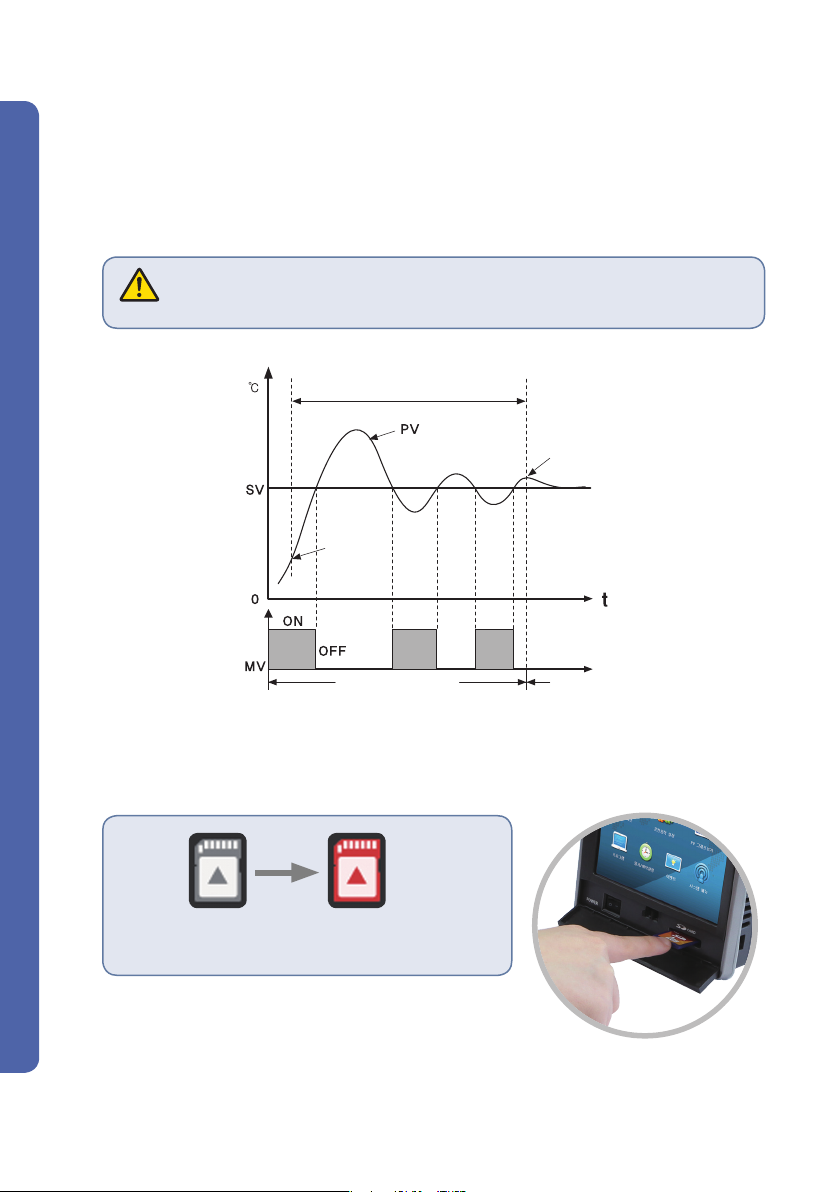
How to Auto Tuning
PID auto tuning is a function for the controller to automatically measure characteristics of control target
in order to calculate and set best PID values. Auto tuning gives ON/OFF control output based on the
setting values and calculates PID integer by measuring hunting cycle and amplitude.
Enter setting values(SV) in the constant-value control mode; run; press button pane; and press
temperature or humidity auto tuning button to run auto tuning. With the auto tuning setting, if zone
selection is set to AUTO, the calculated PID value of zone is automatically saved.
If zone selection is set to MANUAL, it is saved to a specified PID zone.
- If the auto tuning is not completed within 24 hours, it is abandoned. However,
the control operation is continued.
Caution
- If the auto tuning is forcibly ended, PID value is maintained same as before the forcible end.
PID auto tuning section
End of AT
Start of AT
ON/OFF operation PID control section
▶ Recording to SD card
Firstly, insert an SD card as shown.
Programmable Temperature & Humidity Controller
· SD card is recognized as shown.
· If the SD card is not recognized, you can't record to it.
24

1-2. Program operation screen
1) Program operation 1 screen
▶ Concurrent control
- Press Run button in the center left of stop screen of program operation screen 1 in order to switch to the
program operation 1 operation screen.
② ⑩
③ ④
①
⑥
⑤
㉑
⑫
⑬
Fig. 27) Stop screen of program operation screen 1
(Concurrent control)
No. Description
1 Displays state of SD card.
2 Runs hidden menu pane. Click the same to hide menu pane.
3 Go to operation 2 screen.
4 Go to main menu screen.
5 Displays measurement(PV) of channel 1.
6 Displays unit of channel 1.
7 Displays heating control output(H.MV) of channel 1.
8 Displays cooling control output(C.MV) of channel 1. (For heating/cooling control)
9 Enter current setting value(NSV) for channel 1. (Displayed during operation only).
10 Displays ascending/descending/holding state of channel 1.
11 Displays tag name of channel 1 (which may be changed with operation setting).
12 Displays measurement(PV) of channel 2.
13 Displays unit of channel 2.
14 Displays heating control output(H.MV) of channel 2.
15 Displays cooling control output(C.MV) of channel 2. (For heating/cooling control)
16 Enter current setting value(NSV) for channel 2. (Displayed during operation only).
17 Displays ascending/descending/holding state of channel 2.
18 Displays tag name of channel 2 (which may be changed with operation setting).
19 Enter pattern No. for operation.
20 Enter seg No. for operation.
21 Run/stop button.
22
Displays general operation state messages.
23 Displays operation time.
⑰
Fig. 28) Operation screen of program operation screen 1
(Concurrent control)
⑪
⑱
㉒ ㉓ ⑮
⑦
⑲
⑧
⑨
⑳
⑭
⑯
Before starting
Installation
Operation
Screen block
diagram
Function setting Program System setting Specifications
25
 Loading...