

HANYOUNG NUX TD300, TD500 User Manual

TD500/TD300
هﺮﮐ ﮓﻧﺎﯿﻧﺎﻫ تﻻﻮﺼﺤﻣ یرﺎﺼﺤﻧا هﺪﻨﯾﺎ ناﻮﯿﺳ ﺖﮐﴍ
021-33989001
www.sivancarno.com
021-33989002
2 Channel Programmable Temperature Controller
MANUAL

Notice
هﺮﮐ ﮓﻧﺎﯿﻧﺎﻫ تﻻﻮﺼﺤﻣ یرﺎﺼﺤﻧا هﺪﻨﯾﺎ ناﻮﯿﺳ ﺖﮐﴍ
021-33989001
www.sivancarno.com
021-33989002
This user guide is protected by copyright and has all the rights related to it. Without prior authorization
from HANYOUNG, this guide and any parts contained in this guide cannot be reproduced, copied, or
translated in another language.
Contents of this guide will be provided in this form and can be edited or changed without prior
noticed.
This guide includes implied guarantee or suitability for a certain purpose, and it does not offer any
guarantee for those that do not limit this matter.
Every programs contained in this product is protected by copyright. Without prior authorization from
HANYOUNG, this product and any parts contained in this product cannot be reproduced, copied, or
translated in another language.
Every title, symbols, figures, service marks, and etc in this guide or the product are legally registered.
HANYOUNG NUX
28, Gilpa-ro 71beon-gil, Nam-gu, Incheon, Korea
TEL : (82-32)876-4697
FAX : (82-32)876-4696
http://www.hynux.net
E-mail. overseas@hynux.com
3

CONTENTS
هﺮﮐ ﮓﻧﺎﯿﻧﺎﻫ تﻻﻮﺼﺤﻣ یرﺎﺼﺤﻧا هﺪﻨﯾﺎ ناﻮﯿﺳ ﺖﮐﴍ
021-33989001
www.sivancarno.com
021-33989002
1 Before starting
2 Installation instruction
3 Setting and operation
4 Display
5 Function setting
1.1 Checking Product
1.2 Safety Information
2.1 Installation place and caution notice
2.2 Installation method
2.3 Suffix code
2.4 Dimensions / Panel cutout and terminal arrangement
2.5 Terminal arrangement method
3.1 Initial screen
3.2 Basic input mehtod
3.3 Name of operation screen
3.4 Fixed control operation
3.5 Program control operation
3.6 Graph indication and setup
3.7 Errors and indicators for various events
4.1 Operation screen
4.2 Setup screen
5.1 Operation setup
5.2 Time/Timer setup
5.3 Program setup
5
6
7
8
9
9
11
15
15
17
26
27
30
31
32
34
35
36
36
6 System setting
7 Specification
6.1 Sensor input setup
6.2 Control/Transmission setup
6.3 Inner signal setup
6.4 Alarm setup
6.5 PID setup
6.6 Inputs at point of contect (DI) setup
6.7 Point of contact output (DO) setup
6.8 Communication setup
6.9 Other setup
7.1 Input sepcification
7.2 Output specification
7.3 Functions
7.4 Communication
7.5 Ratings
7.6 Operation environment
7.7 Condition of transport and storage
40
41
42
43
43
45
46
48
48
49
49
50
51
51
52
52
4

1 Before starting
هﺮﮐ ﮓﻧﺎﯿﻧﺎﻫ تﻻﻮﺼﺤﻣ یرﺎﺼﺤﻧا هﺪﻨﯾﺎ ناﻮﯿﺳ ﺖﮐﴍ
021-33989001
www.sivancarno.com
021-33989002
Thank you for the purchase of HANYOUNG 2 Loop Temperature Controller (Model : TD500).
This manual contains the function of product, install method, caution information and the way of using
this controller. So please read this manual before using it. And also please make this manual to be
delivered to the final user and to be placed where can be found and seen easily
Contents of this user manual can be edited without prior notice for improvement and modification of the
product
1.1 Checking product
After purchasing our product, please check if it is correct item you want. Also please check breakage
on exterior and omission parts.
If it is a different controller which you want or you find omission parts, please contact our sales office.
1.1.1 TD500
Unit body
1.1.2 TD300
I/O Board 1
Resistance 250Ω × 2
Fixing bracket
40p cable
Manual
Unit body
Fixing bracket
Manual
5

1.2 Safety information
هﺮﮐ ﮓﻧﺎﯿﻧﺎﻫ تﻻﻮﺼﺤﻣ یرﺎﺼﺤﻧا هﺪﻨﯾﺎ ناﻮﯿﺳ ﺖﮐﴍ
021-33989001
www.sivancarno.com
021-33989002
1.2.1. Safety notice
●
For safety and security of the system that is connected to the product, please read and follow this
manual carefully.
●
We are not responsible for any damages and safety problems due to disregards of the manual or
lack of care of the product.
●
Please install any extra safety circuitry or other safety materials outside the product for safety of
the program that is connected to the product.
●
Do not disassemble, repair or reconstruct the product. It can cause electric shock, fire, and errors.
●
Do not give impact to products. It can cause of damage or malfunction.
1.2.2 Quality guarantee
●
Unless it is included company's conditions for warrantee, we are not responsible for any
warranties or guarantees.
●
We are not responsible for any damages and indirect loss of the use or third person due to
unpredicted natural disasters.
1.2.3 Quality guarantee conditions of product
●
The warranty for this product is valid for 1 year from purchase, and we will fix any breakdowns
and faults from proper uses as it is mentioned in this manual for free.
●
After the warranty period, repair will be charged according to our standard policies.
●
Under following conditions, repair will be charged even during warranty period.
•
Breakdowns due to user's misuses
•
Breakdowns due to natural disasters
•
Breakdowns due to moving the product after installation
•
Breakdowns due to modification of the product
•
Breakdowns due to power troubles
●
Please call our customer service for A/S due to breakdowns.
6

2 Installation method
هﺮﮐ ﮓﻧﺎﯿﻧﺎﻫ تﻻﻮﺼﺤﻣ یرﺎﺼﺤﻧا هﺪﻨﯾﺎ ناﻮﯿﺳ ﺖﮐﴍ
021-33989001
www.sivancarno.com
021-33989002
This is information for installation place and method of TD500 (2 loop temperature controller). So please
ready it before installation.
2.1 Installation place and caution notice
2.1.1 Installation place
●
To avoid electric shock, please use it after installation to panel
●
Please avoid installing the product for following places where
•
People can touch terminal unconsciously
•
Directly exposed to the mechanical vibration or impact
•
Exposed to the corrosive gas or combustible gas
• It is exposed to mechanical shock or vibration
• Danger of corrosion or combustion of gas exist
• Temperature changes too frequently
• Temperature is either too high or too low
• It is exposed to direct rays
• It is exposed to electromagnetic waves too much
• Humid place
• It has many combustible objects
• It has dusts and salinity
2.1.2 Caution
●
The case of this controller is chrome-zinc plating and Bezel is made by ABS/PC anti-combustion
material but please not install it to the inflammable place. Especially please do not put it on the
inflammable products.
●
Please keep it away from the machine or wires that can be cause of noise.
Especially, please have enough warn-up when you operate it under 10 ℃ temperature.
●
Please install it on horizontally
●
When you wire it, please cut out all of electric power.
●
This controller is operating in 100 - 240 V AC, 50-60 Hz without additional change.
If you use other voltage, it may case of fire and electric shock.
●
Do not operate controller with wet hand, it may cause of electric shock.
●
Please follow Safety Information to prevent any fire, electric shock and any damage.
●
Please follow this manual for install and operation of this controller.
●
When you put to earth, please refer to install method. But do not it earth to gas pipes, phone lines
and lightning rods
●
Please do not turn on power until you install all of parts
●
Please do not block ventilating windows. It may cause of break down.
●
The grade of over voltage is CatalogueⅡ and using environment is DegreeⅡ
7

2.2 Installation method
هﺮﮐ ﮓﻧﺎﯿﻧﺎﻫ تﻻﻮﺼﺤﻣ یرﺎﺼﺤﻧا هﺪﻨﯾﺎ ناﻮﯿﺳ ﺖﮐﴍ
021-33989001
www.sivancarno.com
021-33989002
(1) Please use 1 mm ~ 10 mm thickness of a steel sheet for panel.
(2) In front of panel, please push into TD500 temperature controller
(3) Using fixing bracket, please adhere controller to the panel
(4) If you tighten it up by fixing iron to panel, it can be cause break of case or fixing bracket.
Caution
●
To prevent electric shock, please check 'turn off power'
●
Before turn on power, please connect over the third
class grounding.
●
During retransmission, it may cause electric shock so
please do not touch terminal.
●
Please wire it after turn off main power
●
Please contact around 2A fuse to main electronic power line.
8

2.3 Suffix Code
هﺮﮐ ﮓﻧﺎﯿﻧﺎﻫ تﻻﻮﺼﺤﻣ یرﺎﺼﺤﻧا هﺪﻨﯾﺎ ناﻮﯿﺳ ﺖﮐﴍ
021-33989001
www.sivancarno.com
021-33989002
MODEL CODE DESCRIPTION
TD500 2 LOOP PROGRAMMABLE TEMPERATURE CONTROLLER
N NONE
BODY
(SEPARA TYPE)
1 SEPARATE BODY(RS422/485 + USB)
2 SEPARATE BODY(RS232C + USB)
BODY(UNIT)
I/O BOARD
3 UNIT BODY(RS422/485 + USB), I/O TERMINAL BUILT-IN
4 UNIT BODY(RS232C + USB), I/O TERMINAL BUILT-IN
N NO I/O BOARD
1 SEPARATE TYPE I/O BOARD
2.4 Dimensions / Panel cutout and Terminal arrangement
2.4.1. TD500 Unit body
[unit : mm]
9

2.4.2 TD500 I/O board
هﺮﮐ ﮓﻧﺎﯿﻧﺎﻫ تﻻﻮﺼﺤﻣ یرﺎﺼﺤﻧا هﺪﻨﯾﺎ ناﻮﯿﺳ ﺖﮐﴍ
021-33989001
www.sivancarno.com
021-33989002
2.4.3. TD500 Body terminal arrangement
[unit : mm]
2.4.3. TD500 I/O Board terminal arrangement
10

2.5 Terminal arrangement method
هﺮﮐ ﮓﻧﺎﯿﻧﺎﻫ تﻻﻮﺼﺤﻣ یرﺎﺼﺤﻧا هﺪﻨﯾﺎ ناﻮﯿﺳ ﺖﮐﴍ
021-33989001
www.sivancarno.com
021-33989002
2.5.1 Power
● Grounding needs over 2 mm 2 wire and at least the third
class grounding connection (Grounding resistance below
100Ω). Grounding cable should be within 20 meters.
2.5.2 Sensor Input
Caution
• Please use input wire with shield. And the shield needs to have
1 point grounding.
• Please leave a space for Sensor line against power line or
grounding line.
11

2.5.3 Control output and retransmission arrangement
هﺮﮐ ﮓﻧﺎﯿﻧﺎﻫ تﻻﻮﺼﺤﻣ یرﺎﺼﺤﻧا هﺪﻨﯾﺎ ناﻮﯿﺳ ﺖﮐﴍ
021-33989001
www.sivancarno.com
021-33989002
Caution
•
Please pay attention about output polarity when you wire
•
Please use shield line for output line. And shield needs
1 point ground.
2.5.4 Relay out
12
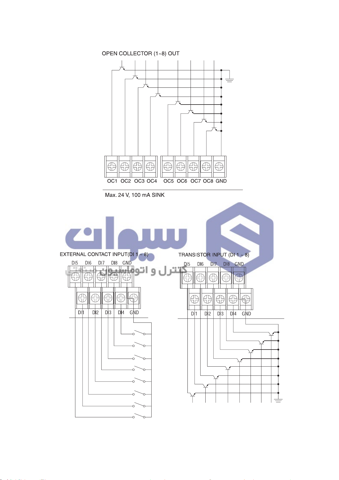
2.5.5 Transistor (O/C) output
هﺮﮐ ﮓﻧﺎﯿﻧﺎﻫ تﻻﻮﺼﺤﻣ یرﺎﺼﺤﻧا هﺪﻨﯾﺎ ناﻮﯿﺳ ﺖﮐﴍ
021-33989001
www.sivancarno.com
021-33989002
2.5.6 Contact input
13

2.5.7 Communication arrangement
هﺮﮐ ﮓﻧﺎﯿﻧﺎﻫ تﻻﻮﺼﺤﻣ یرﺎﺼﺤﻧا هﺪﻨﯾﺎ ناﻮﯿﺳ ﺖﮐﴍ
021-33989001
www.sivancarno.com
021-33989002
•RS422/RS485 arrangement
TD500 can contact maximum 256 machines.
Please contact Terminating Resistance (100 ~ 200 Ω 1/2 W) to the both of ends for
communication lines.
RS485 Connection (2 Wires)
RS422 Connection (4 Wires)
•RS232 arrangement
14

3 Setting and Operation
هﺮﮐ ﮓﻧﺎﯿﻧﺎﻫ تﻻﻮﺼﺤﻣ یرﺎﺼﺤﻧا هﺪﻨﯾﺎ ناﻮﯿﺳ ﺖﮐﴍ
021-33989001
www.sivancarno.com
021-33989002
3.1 Initial screen
When the power is turned on after installation, the logo screen is indicated for 3 seconds, after
which the first operation screen is shown. (Logo screen can be changed by the user through
communication functionality.)
3.2 Basic input method
[Table 1]
Category of Buttons Name Function
Selection
Button
Activation Input
Box
Deactivation
Input Box
Button selected by the need of the users. When pressed,
the button is reversed, and the corresponding operation is
selected while the button is being released.
Window to set various settings needed by the users. When
pressed, the corresponding range of numbers or characters
input window appears, and the needed value is to be pressed.
Although it’s an input window, depending on the current
condition or status, this window is deactivated. When the
condition is met, it is converted to an activated input window.
15

3.2.1 Numerical Input Window
هﺮﮐ ﮓﻧﺎﯿﻧﺎﻫ تﻻﻮﺼﺤﻣ یرﺎﺼﺤﻧا هﺪﻨﯾﺎ ناﻮﯿﺳ ﺖﮐﴍ
021-33989001
www.sivancarno.com
021-33989002
Positive and real numbers can be inputted at the
basic number input window. On the top left, the
`input area'and 'max/min value' are indicated,
and the current input value is indicated on the
number board's indication box. The input number is
inputted when the button is pressed, and if
is pressed beforehand, the current input is
cancelled.
3.2.2 Character Input Window (Korean/English/Numeric Character)
Character input is possible. It is shown when setting the pattern name, contact input (DI) name and
etc. Korean/English/Numeric Character conversion is possible by using the keyboard conversion
button.
16

3.3 Name of operation screen
هﺮﮐ ﮓﻧﺎﯿﻧﺎﻫ تﻻﻮﺼﺤﻣ یرﺎﺼﺤﻧا هﺪﻨﯾﺎ ناﻮﯿﺳ ﺖﮐﴍ
021-33989001
www.sivancarno.com
021-33989002
① ② ③
④
⑦
⑩
⑫ ⑬⑭ ⑯
(1st Screen for Fixed Control Operation, 2 channel simultaneous operation mode)
No. Name No. Name
⑪
⑤
⑥
⑧
⑨
⑮
⑰
①
Current screen information
②
Menu button for function setting
③
Conversion button to next screen
④
CH.1 Process Value(PV) display
⑤
CH.1 Target Set Value(TSV) input box
⑥
CH.1 Current target set value display
⑦
CH.2 Process Value(PV) display
⑧
CH.2 Target Set Value(TSV) input box
⑨
CH.2 Current target set value display
⑩
CH.1 PID zone input box
⑪
CH.2 PID zone input box
⑫
CH.1 A.T button
⑬
CH.2 A.T button
⑭
Current Date / Time display
⑮
Operation progress time
⑯
Operation Start button
⑰
Operation Stop button
17
 Loading...